Skip to content
  • MySensors
  • OpenHardware.io
  • Categories
  • Recent
  • Tags
  • Popular
Skins
  • Light
  • Brite
  • Cerulean
  • Cosmo
  • Flatly
  • Journal
  • Litera
  • Lumen
  • Lux
  • Materia
  • Minty
  • Morph
  • Pulse
  • Sandstone
  • Simplex
  • Sketchy
  • Spacelab
  • United
  • Yeti
  • Zephyr
  • Dark
  • Cyborg
  • Darkly
  • Quartz
  • Slate
  • Solar
  • Superhero
  • Vapor

  • Default (No Skin)
  • No Skin
Collapse
Brand Logo
  1. Home
  2. Hardware
  3. In wall - PCB, (AC to DC 5v)

In wall - PCB, (AC to DC 5v)

Scheduled Pinned Locked Moved Hardware
pcbinwall
89 Posts 14 Posters 66.2k Views 24 Watching
  • Oldest to Newest
  • Newest to Oldest
  • Most Votes
Reply
  • Reply as topic
Log in to reply
This topic has been deleted. Only users with topic management privileges can see it.
  • bjacobseB Offline
    bjacobseB Offline
    bjacobse
    wrote on last edited by
    #15

    Looks great, will you consider to create a version with 2 relays so it will be similar like the Fibaro 2 relay or Qubino 2 relay
    I also live in Sweden (Using same wall mechanical dimensions) and are searching exactly for a Mysensor relay 2 device to hide in the wall

    link to Fibaro 2 Relay zwave device

    1 Reply Last reply
    0
    • sundberg84S Offline
      sundberg84S Offline
      sundberg84
      Hardware Contributor
      wrote on last edited by sundberg84
      #16

      @bjacobse My thought was to first create one working pcb to start with and leave the upper side for sensors.
      This way you can recreate that upper pcb for the needs you have and just add it as a shield to the lower pcb.

      Controller: Proxmox VM - Home Assistant
      MySensors GW: Arduino Uno - W5100 Ethernet, Gw Shield Nrf24l01+ 2,4Ghz
      MySensors GW: Arduino Uno - Gw Shield RFM69, 433mhz
      RFLink GW - Arduino Mega + RFLink Shield, 433mhz

      1 Reply Last reply
      0
      • scalzS Offline
        scalzS Offline
        scalz
        Hardware Contributor
        wrote on last edited by
        #17

        @sundberg84: hi nice idea :smiley:
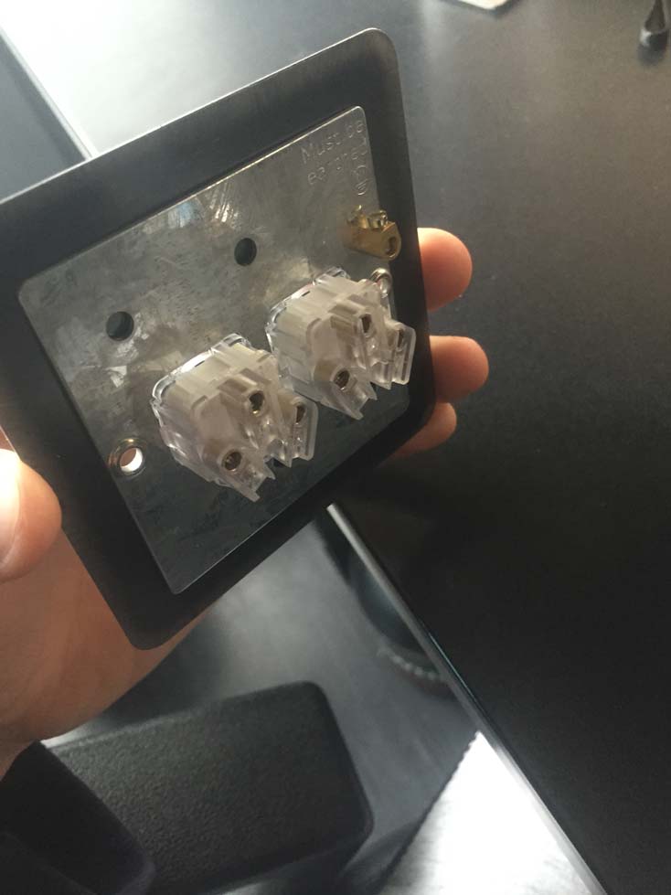
        just for curiosity, what does "sweden" box look like??? I live in France, and here the most common style/size is like this: http://www.leroymerlin.fr/v3/p/produits/boite-d-encastrement-legrand-pour-mur-creux-d-67-mm-e29984
        is it like yours??

        1 Reply Last reply
        0
        • korttomaK Offline
          korttomaK Offline
          korttoma
          Hero Member
          wrote on last edited by
          #18

          This is what I have in my walls and these in the roof in a house in Finland. I bet they are similar in Sweden.

          • Tomas
          1 Reply Last reply
          0
          • scalzS Offline
            scalzS Offline
            scalz
            Hardware Contributor
            wrote on last edited by scalz
            #19

            thx :smile:
            it seems you have good quality/strong box :wink: not cheap, a little bit bigger than ours. interesting to see difference. so in future, if I will make something inwall for me, it will fit to "nordic" box. cool. unfortunately maybe not the holes...I will check this. but it's not a big problem I think. good to know.

            1 Reply Last reply
            0
            • sundberg84S Offline
              sundberg84S Offline
              sundberg84
              Hardware Contributor
              wrote on last edited by
              #20

              Yea. Mine is about d =6,5 mm as well. Reminds of yours.

              Controller: Proxmox VM - Home Assistant
              MySensors GW: Arduino Uno - W5100 Ethernet, Gw Shield Nrf24l01+ 2,4Ghz
              MySensors GW: Arduino Uno - Gw Shield RFM69, 433mhz
              RFLink GW - Arduino Mega + RFLink Shield, 433mhz

              1 Reply Last reply
              0
              • sundberg84S Offline
                sundberg84S Offline
                sundberg84
                Hardware Contributor
                wrote on last edited by
                #21

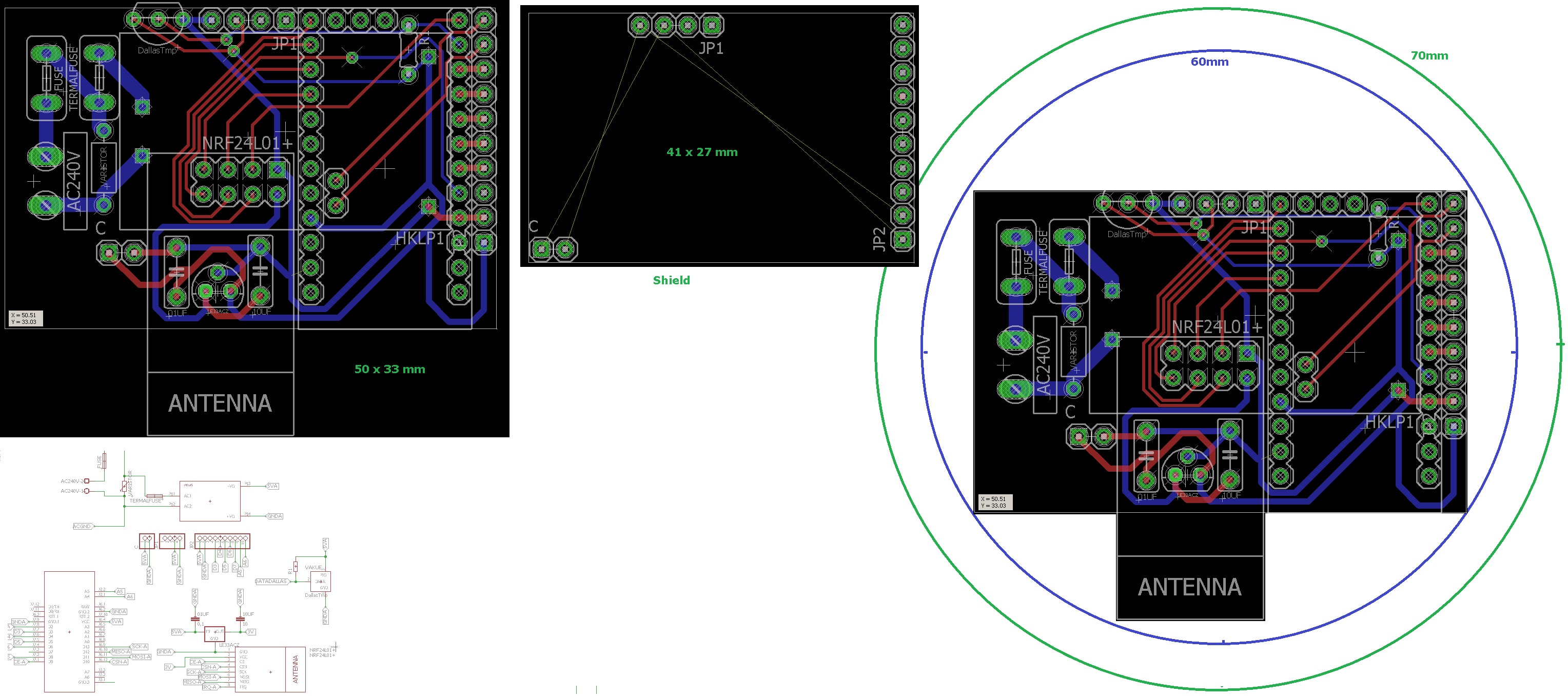
                I ended up re-thinking this - and I think this is better.
                Now all components are located to 1 pcb, with an empty shield.
                This makes it possible to have a standard PCB and just create the shield or make one from a empty board.

                @m26872 and everyone else - my biggest consern is the distanse between the high power and rest - what do you think? Im no expert.

                1.jpg

                Controller: Proxmox VM - Home Assistant
                MySensors GW: Arduino Uno - W5100 Ethernet, Gw Shield Nrf24l01+ 2,4Ghz
                MySensors GW: Arduino Uno - Gw Shield RFM69, 433mhz
                RFLink GW - Arduino Mega + RFLink Shield, 433mhz

                1 Reply Last reply
                0
                • S Offline
                  S Offline
                  Samuel235
                  Hardware Contributor
                  wrote on last edited by Samuel235
                  #22

                  The issue that i personally have at the moment with locating this style of sensor behind a switch is that the slimline boxes in UK have around 15mm of room (depth) inside once the switch itself is fitted. There is slightly more room around the sides but the middle section is around 15mm. I'm now wondering how hard it would be to maybe create a slimmer version or slightly longer, say 70/75mm in length?

                  MySensors 2.1.1
                  Controller - OpenHAB (Virtual Machine)
                  Gateway - Arduino Mega MQTT Gateway W5100

                  1 Reply Last reply
                  0
                  • sundberg84S Offline
                    sundberg84S Offline
                    sundberg84
                    Hardware Contributor
                    wrote on last edited by sundberg84
                    #23

                    @samuel235 That is out of my leauge! 10-15mm is pretty much a PCB with the arduino on it. Adding the HLK transformer its like 20-25mm.
                    Even if i would fit everything on one side the PCB and the HLK transformer should be hard to fit i think.

                    Controller: Proxmox VM - Home Assistant
                    MySensors GW: Arduino Uno - W5100 Ethernet, Gw Shield Nrf24l01+ 2,4Ghz
                    MySensors GW: Arduino Uno - Gw Shield RFM69, 433mhz
                    RFLink GW - Arduino Mega + RFLink Shield, 433mhz

                    1 Reply Last reply
                    0
                    • S Offline
                      S Offline
                      Samuel235
                      Hardware Contributor
                      wrote on last edited by
                      #24

                      This is where we create stable ones for your socket boxes, then i'll attempt to lay something out in terms of design if possible for a UK version. Lets get a working and stable version of yours going first and we could take it from there i guess.

                      MySensors 2.1.1
                      Controller - OpenHAB (Virtual Machine)
                      Gateway - Arduino Mega MQTT Gateway W5100

                      1 Reply Last reply
                      1
                      • scalzS Offline
                        scalzS Offline
                        scalz
                        Hardware Contributor
                        wrote on last edited by
                        #25

                        @sundberg84: I'm not expert too, I don't know if it can help you. I hope..

                        • why not move hilink a little bit on the left...is it what you are talking about? clearance between hilink and nrf? - or about fuse...maybe for fuse...pads could be a little bit smaller. it won't drain too much current so..
                          if you dont move hilink, maybe increase space between thermal fuse and hilink and the route between them less straight, add a little upper angle, miter/round it a little if you want. but not too near dallastemp of course you know.I guess you want to keep your ac connector middle centered too.
                        • If you want to move hilink, you can maybe change few route like this. there are better ways, sure. I have not looked longtime I hope I don't say dumb things lol, I'm not a pcb expert too. sometimes I can't get the route like I want, and the day after, hop, I see it! :laughing:
                          2015-12-02_02-02-54.png
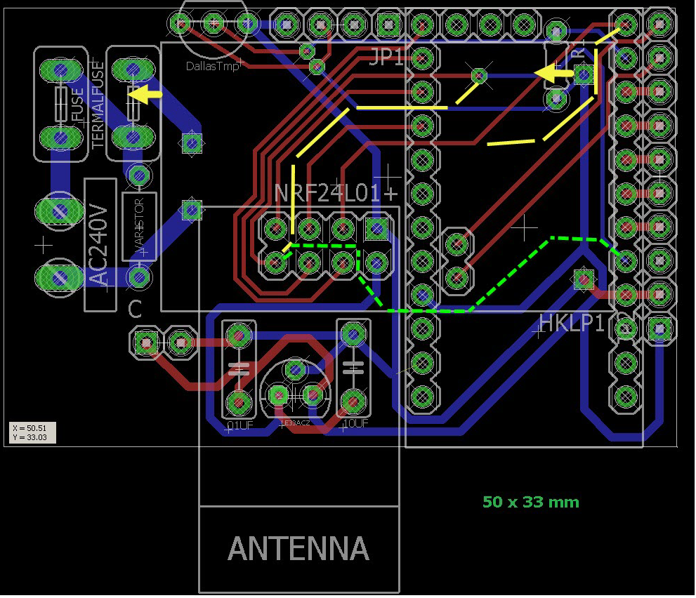
                          If you have some problems sometimes to get gnd, do you use gnd plane. useful too, but not on ac lol..I think you maybe already know it.
                          Will you have some holes? how do you plan to fix it inside?
                        1 Reply Last reply
                        1
                        • S Offline
                          S Offline
                          Samuel235
                          Hardware Contributor
                          wrote on last edited by Samuel235
                          #26

                          IMG_6883.JPG IMG_6882.JPG
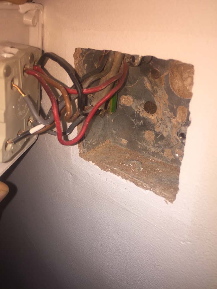
                          So, this is what i have to contend with. Inside the socket i need to fit an arduino, nano or mini and some form of power supply (cell battery looks the only way) an nRF24L01 and then connect it to the rear of the switch. I may have to create my own board and arduino to reduce the footprint of my design to enable it to fit. Idealy i want to keep those current wires in the box but terminated, simply so if we move house all we need to do would be to remove the terminals and rewire into the switch.

                          MySensors 2.1.1
                          Controller - OpenHAB (Virtual Machine)
                          Gateway - Arduino Mega MQTT Gateway W5100

                          1 Reply Last reply
                          0
                          • martinhjelmareM Offline
                            martinhjelmareM Offline
                            martinhjelmare
                            Plugin Developer
                            wrote on last edited by martinhjelmare
                            #27

                            I've been thinking about installing a PCB with transformer in the wall myself. I like this project, but how do you feel about leaving exposed high voltage circuitry in the wall box. Normally the wires in the box should have at least one layer of insulation and splicing should be done inside insulated caps. Don't know all the correct terms in English, so I hope you understand what I mean.

                            Ideally I'd want a box for the PCB inside the wall box, but that will probably never fit. Right now my plan is to put a new box on the outside of the wall next to the coupling box up under the ceiling vertically ~ 120 cm from the wall box with the buttons for the lamps etc. But in my basement there are no coupling boxes under the ceiling, so there I'm forced to put everything inside the wall box, if I want it to look good.

                            Any other ideas?

                            S m26872M 2 Replies Last reply
                            0
                            • martinhjelmareM martinhjelmare

                              I've been thinking about installing a PCB with transformer in the wall myself. I like this project, but how do you feel about leaving exposed high voltage circuitry in the wall box. Normally the wires in the box should have at least one layer of insulation and splicing should be done inside insulated caps. Don't know all the correct terms in English, so I hope you understand what I mean.

                              Ideally I'd want a box for the PCB inside the wall box, but that will probably never fit. Right now my plan is to put a new box on the outside of the wall next to the coupling box up under the ceiling vertically ~ 120 cm from the wall box with the buttons for the lamps etc. But in my basement there are no coupling boxes under the ceiling, so there I'm forced to put everything inside the wall box, if I want it to look good.

                              Any other ideas?

                              S Offline
                              S Offline
                              Samuel235
                              Hardware Contributor
                              wrote on last edited by
                              #28

                              @martinhjelmare In your case it would be high voltage open circuitry as you plan on running it on the existing power lines that are there currently. If i understand what you're saying anyway, am i correct? However, in my case, i plan on terminating the existing wires in a terminal block or taping them off if possible to save space, then have my sensor node running off of a custom PCB holding a custom made Arduino to save even more space and then run the whole board off of a cell coin battery.

                              MySensors 2.1.1
                              Controller - OpenHAB (Virtual Machine)
                              Gateway - Arduino Mega MQTT Gateway W5100

                              martinhjelmareM 1 Reply Last reply
                              0
                              • S Samuel235

                                @martinhjelmare In your case it would be high voltage open circuitry as you plan on running it on the existing power lines that are there currently. If i understand what you're saying anyway, am i correct? However, in my case, i plan on terminating the existing wires in a terminal block or taping them off if possible to save space, then have my sensor node running off of a custom PCB holding a custom made Arduino to save even more space and then run the whole board off of a cell coin battery.

                                martinhjelmareM Offline
                                martinhjelmareM Offline
                                martinhjelmare
                                Plugin Developer
                                wrote on last edited by
                                #29

                                @samuel235

                                My worry, when having exposed high voltage circuitry inside a standard wall box, with otherwise insulated wires, is that someone else than me, for example an electrician, might poke around unknowingly in the box and get electrocuted. If you have the PCB inside a separate box with warning label, the risk is at least slightly lower.

                                S 1 Reply Last reply
                                0
                                • martinhjelmareM martinhjelmare

                                  @samuel235

                                  My worry, when having exposed high voltage circuitry inside a standard wall box, with otherwise insulated wires, is that someone else than me, for example an electrician, might poke around unknowingly in the box and get electrocuted. If you have the PCB inside a separate box with warning label, the risk is at least slightly lower.

                                  S Offline
                                  S Offline
                                  Samuel235
                                  Hardware Contributor
                                  wrote on last edited by
                                  #30

                                  @martinhjelmare I would agree, with your situation, and like that proposed on this PCB design (@sundberg84, please correct me if i'm wrong), like i said in my previous post. You should either conceal them or avoid using them. That is what i would advise (using UK/British rules and regulations).

                                  MySensors 2.1.1
                                  Controller - OpenHAB (Virtual Machine)
                                  Gateway - Arduino Mega MQTT Gateway W5100

                                  1 Reply Last reply
                                  0
                                  • sundberg84S Offline
                                    sundberg84S Offline
                                    sundberg84
                                    Hardware Contributor
                                    wrote on last edited by sundberg84
                                    #31

                                    Maybe someone could open a own thread discussing this with a battery operated in wall node.
                                    For example, someone needs to put a circiut diagram for how to operera that relay with power only from the battery.

                                    Controller: Proxmox VM - Home Assistant
                                    MySensors GW: Arduino Uno - W5100 Ethernet, Gw Shield Nrf24l01+ 2,4Ghz
                                    MySensors GW: Arduino Uno - Gw Shield RFM69, 433mhz
                                    RFLink GW - Arduino Mega + RFLink Shield, 433mhz

                                    1 Reply Last reply
                                    0
                                    • martinhjelmareM martinhjelmare

                                      I've been thinking about installing a PCB with transformer in the wall myself. I like this project, but how do you feel about leaving exposed high voltage circuitry in the wall box. Normally the wires in the box should have at least one layer of insulation and splicing should be done inside insulated caps. Don't know all the correct terms in English, so I hope you understand what I mean.

                                      Ideally I'd want a box for the PCB inside the wall box, but that will probably never fit. Right now my plan is to put a new box on the outside of the wall next to the coupling box up under the ceiling vertically ~ 120 cm from the wall box with the buttons for the lamps etc. But in my basement there are no coupling boxes under the ceiling, so there I'm forced to put everything inside the wall box, if I want it to look good.

                                      Any other ideas?

                                      m26872M Offline
                                      m26872M Offline
                                      m26872
                                      Hardware Contributor
                                      wrote on last edited by
                                      #32

                                      I agree with @martinhjelmare I just assumed there would be some other insulation and it would be the second step of the design. Good you cleared this out early.
                                      I think it is almost possible, but really hard, to copy the size and shape of commercial in-wall devices and still fit in all we want. Small customized PSUs may be necessary.
                                      Personally I'd prefer external boxes. They could be in wall as well, as long as there's space for safe (diy) designs or even future projects.

                                      1 Reply Last reply
                                      0
                                      • martinhjelmareM Offline
                                        martinhjelmareM Offline
                                        martinhjelmare
                                        Plugin Developer
                                        wrote on last edited by
                                        #33

                                        I'm thinking I'd like to try and design a custom box for 3d printing that could fit this project by @sundberg84 and also fit inside the wall box. Has this been done already and do you think it's worthwhile, i.e. is it possible?

                                        1 Reply Last reply
                                        0
                                        • sundberg84S Offline
                                          sundberg84S Offline
                                          sundberg84
                                          Hardware Contributor
                                          wrote on last edited by sundberg84
                                          #34

                                          What I know of, this has not been done before... not the PCB or the 3d printing.
                                          Good points taken above! We need to consider this and this might not be the optimal design.
                                          Maybe thought was that this design can break some ground and maybe it can lead to better and even smaller designs.

                                          I like my designs easy :) Pro Minis with ready bootloaders so everyone can be inluded, but this might not be possible...
                                          I will still finish my design and see how it looks.

                                          Controller: Proxmox VM - Home Assistant
                                          MySensors GW: Arduino Uno - W5100 Ethernet, Gw Shield Nrf24l01+ 2,4Ghz
                                          MySensors GW: Arduino Uno - Gw Shield RFM69, 433mhz
                                          RFLink GW - Arduino Mega + RFLink Shield, 433mhz

                                          1 Reply Last reply
                                          0
                                          Reply
                                          • Reply as topic
                                          Log in to reply
                                          • Oldest to Newest
                                          • Newest to Oldest
                                          • Most Votes


                                          8

                                          Online

                                          11.7k

                                          Users

                                          11.2k

                                          Topics

                                          113.0k

                                          Posts


                                          Copyright 2019 TBD   |   Forum Guidelines   |   Privacy Policy   |   Terms of Service
                                          • Login

                                          • Don't have an account? Register

                                          • Login or register to search.
                                          • First post
                                            Last post
                                          0
                                          • MySensors
                                          • OpenHardware.io
                                          • Categories
                                          • Recent
                                          • Tags
                                          • Popular