In wall - PCB, (AC to DC 5v)
-
@samuel235 You can test and monitor the performance. Watch also this antenna modification by @petewill https://www.youtube.com/watch?v=NpMnauHeR7Y
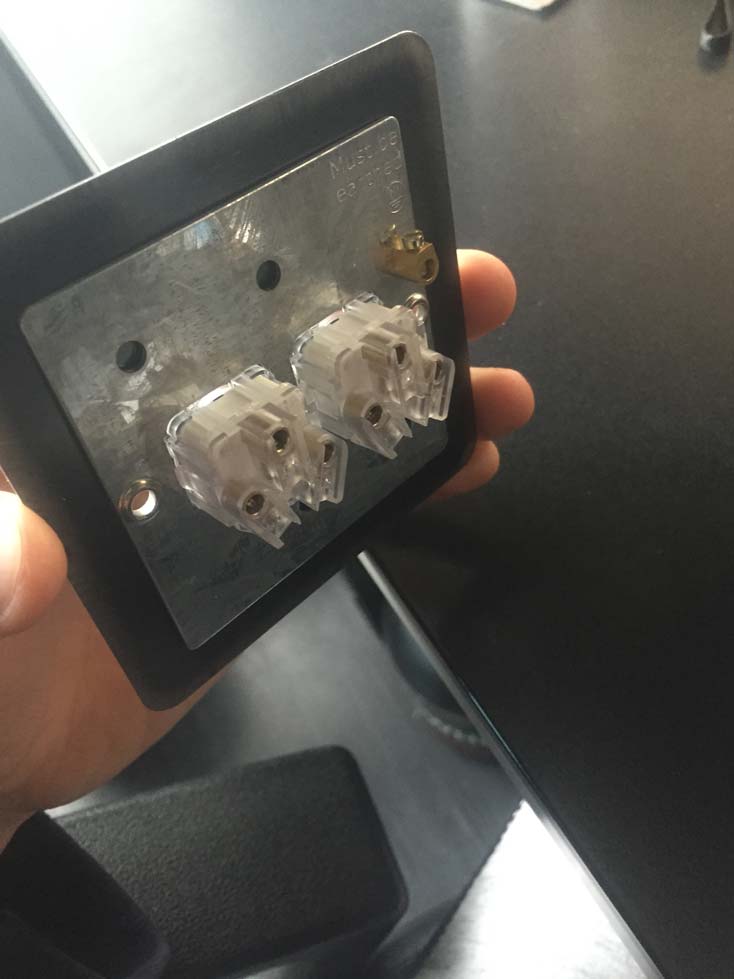
@ahmedadelhosni I have seen how you can increase the signal reading capabilities, i was just wondering if the steel backbox would affect the rate at which the signal came into the radio with it being inside of the metal box.
-
@samuel235 Probably! I had this problem when i had the radion in between two pcb a while ago. Relocating the radio changed the effect on it so I think there might be problem if ju isolate the radio with metal.
-
This post is archived!
Please use this thread to post questions:https://forum.mysensors.org/topic/2783/in-wall-ac-dc-pcb-for-mysensors
Project can be found here:
https://www.openhardware.io/view/13/In-Wall-ACDC-Pcb-for-MySensors
Hi!
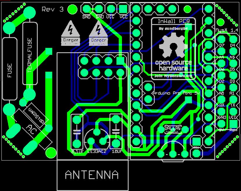
As i mentioned in another post i had this idea to stack two PCB on top of each other to fit inside a wall appliance box. This idea has evolved (see below).
Im aware of the big security risk here, and have tried to read:
- http://forum.mysensors.org/topic/1607/safe-in-wall-ac-to-dc-transformers
- http://forum.mysensors.org/topic/1540/110v-230v-ac-to-mysensors-pcb-board
EDIT 03/1/2016
After discussion on this here are the findings of this thread (as of now):I will update this post with BOM and eagles files as soon as i get a node running.
...............................
BOM/README: http://1drv.ms/1kCzue5
GERBER: InWallMySensor3.0.rar
EAGLES: InWallMySensor3.0Eagles.rar
Build images: http://1drv.ms/1lsleox
...............................If you are using this design, please know about the risks when you work with high power. This design has no guarantee s so use it on your own risk!
@sundberg84 I don't like the creepage distance to those display-pins in the middle of the relay footprint. It looks like there's plenty of space to move it, eg beneath "sensors". Also due to the EMI-risk from relay switch.
Maybe you also want increase the width and solder-mask the middle of the relay high power traces.
The panelizing holes will probably be hard to break without damage to the pads. At least try to move them closer together.
-
So, i need to test my module inside of a metal backbox then, and if it receives interference we could do with coming up for a solution because most of the 'older' UK Style houses that i work within use metal back boxes. So if we could come up with a work around, it would broaden the possible audience.
-
@samuel235 I would have tried to attach the radio with jumper wires and put the radio outside the metal box somehow.
-
That would be incredibly difficult to do if you're using a metal box purely for the reason of having no room between the brick and the plasterboard (Or whatever finished product you use over where you live).
-
That would be incredibly difficult to do if you're using a metal box purely for the reason of having no room between the brick and the plasterboard (Or whatever finished product you use over where you live).
-
@samuel235 You will probably have to face the radio so it's pointing through the plastic cover (not the metal box) and use repeaters in the rooms where necessary.
-
Looks great, will you consider to create a version with 2 relays so it will be similar like the Fibaro 2 relay or Qubino 2 relay
I also live in Sweden (Using same wall mechanical dimensions) and are searching exactly for a Mysensor relay 2 device to hide in the wall -
@bjacobse My thought was to first create one working pcb to start with and leave the upper side for sensors.
This way you can recreate that upper pcb for the needs you have and just add it as a shield to the lower pcb. -
@sundberg84: hi nice idea :smiley:
just for curiosity, what does "sweden" box look like??? I live in France, and here the most common style/size is like this: http://www.leroymerlin.fr/v3/p/produits/boite-d-encastrement-legrand-pour-mur-creux-d-67-mm-e29984
is it like yours?? -
thx :smile:
it seems you have good quality/strong box :wink: not cheap, a little bit bigger than ours. interesting to see difference. so in future, if I will make something inwall for me, it will fit to "nordic" box. cool. unfortunately maybe not the holes...I will check this. but it's not a big problem I think. good to know. -
Yea. Mine is about d =6,5 mm as well. Reminds of yours.
-
I ended up re-thinking this - and I think this is better.
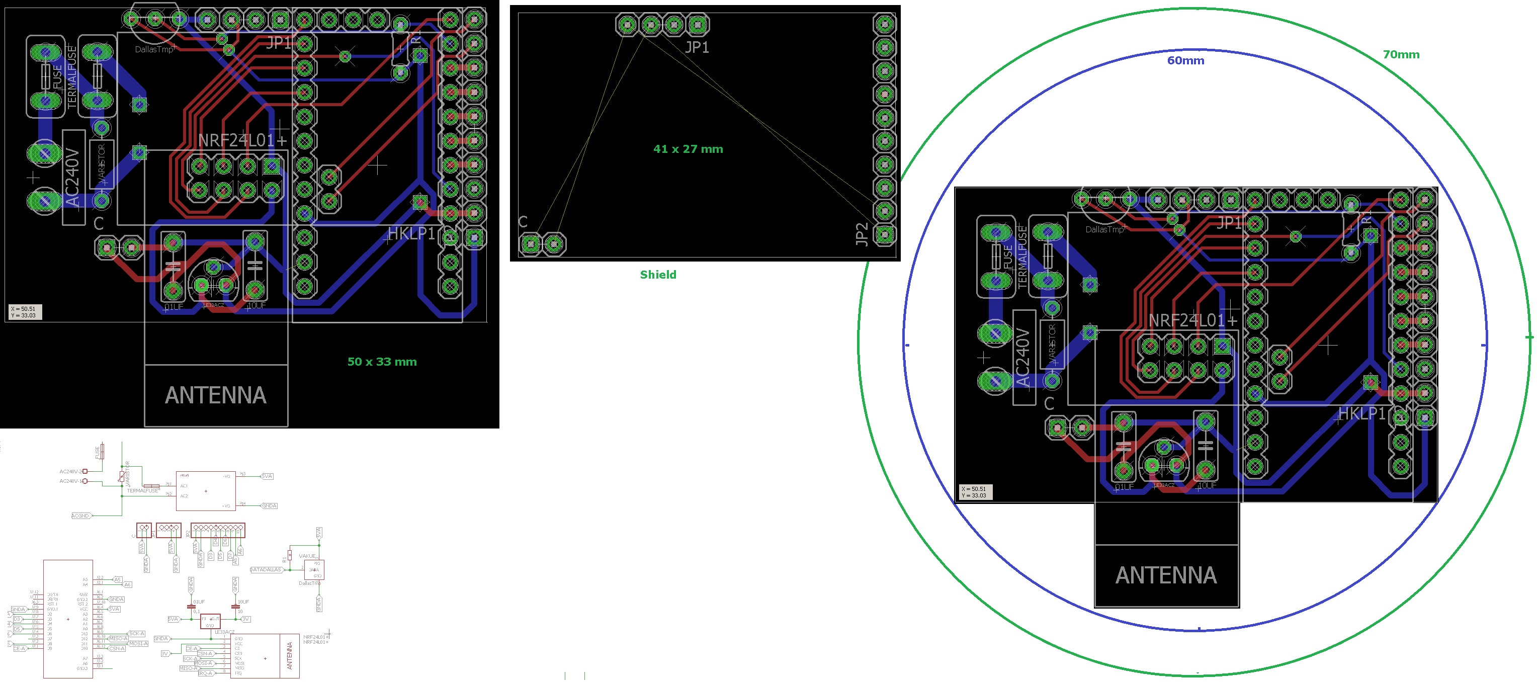
Now all components are located to 1 pcb, with an empty shield.
This makes it possible to have a standard PCB and just create the shield or make one from a empty board.@m26872 and everyone else - my biggest consern is the distanse between the high power and rest - what do you think? Im no expert.
-
The issue that i personally have at the moment with locating this style of sensor behind a switch is that the slimline boxes in UK have around 15mm of room (depth) inside once the switch itself is fitted. There is slightly more room around the sides but the middle section is around 15mm. I'm now wondering how hard it would be to maybe create a slimmer version or slightly longer, say 70/75mm in length?
-
@samuel235 That is out of my leauge! 10-15mm is pretty much a PCB with the arduino on it. Adding the HLK transformer its like 20-25mm.
Even if i would fit everything on one side the PCB and the HLK transformer should be hard to fit i think. -
This is where we create stable ones for your socket boxes, then i'll attempt to lay something out in terms of design if possible for a UK version. Lets get a working and stable version of yours going first and we could take it from there i guess.
-
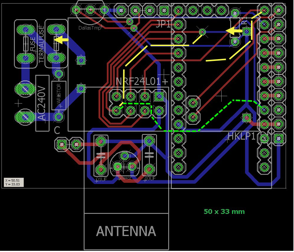
@sundberg84: I'm not expert too, I don't know if it can help you. I hope..
- why not move hilink a little bit on the left...is it what you are talking about? clearance between hilink and nrf? - or about fuse...maybe for fuse...pads could be a little bit smaller. it won't drain too much current so..
if you dont move hilink, maybe increase space between thermal fuse and hilink and the route between them less straight, add a little upper angle, miter/round it a little if you want. but not too near dallastemp of course you know.I guess you want to keep your ac connector middle centered too. - If you want to move hilink, you can maybe change few route like this. there are better ways, sure. I have not looked longtime I hope I don't say dumb things lol, I'm not a pcb expert too. sometimes I can't get the route like I want, and the day after, hop, I see it! :laughing:
If you have some problems sometimes to get gnd, do you use gnd plane. useful too, but not on ac lol..I think you maybe already know it.
Will you have some holes? how do you plan to fix it inside?
- why not move hilink a little bit on the left...is it what you are talking about? clearance between hilink and nrf? - or about fuse...maybe for fuse...pads could be a little bit smaller. it won't drain too much current so..
-
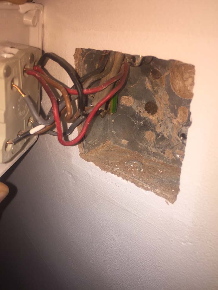
So, this is what i have to contend with. Inside the socket i need to fit an arduino, nano or mini and some form of power supply (cell battery looks the only way) an nRF24L01 and then connect it to the rear of the switch. I may have to create my own board and arduino to reduce the footprint of my design to enable it to fit. Idealy i want to keep those current wires in the box but terminated, simply so if we move house all we need to do would be to remove the terminals and rewire into the switch.
Hello! It looks like you're interested in this conversation, but you don't have an account yet.
Getting fed up of having to scroll through the same posts each visit? When you register for an account, you'll always come back to exactly where you were before, and choose to be notified of new replies (either via email, or push notification). You'll also be able to save bookmarks and upvote posts to show your appreciation to other community members.
With your input, this post could be even better 💗
Register Login