2 channel in wall dimmer
-
@Denke Nice :) I am really excited to see your results.
Regarding the resistor which is in parallel to act as a bleeder. What value do you think the most suitable ? 100K ? 1M ? and howa much watt ?Thanks.
-
@Denke Nice :) I am really excited to see your results.
Regarding the resistor which is in parallel to act as a bleeder. What value do you think the most suitable ? 100K ? 1M ? and howa much watt ?Thanks.
@ahmedadelhosni
Hi I have used 1M as bleeder in 0603 size. This resistor should be able to handle around 0.1W.If i have calculated right the power in the bleeder resistor should be around 0.05W
-
Any pictures of the assembled board ?
-
Any pictures of the assembled board ?
@ahmedadelhosni Have not started the assembly of these boards yet. Im currently doing assembly of my other project Wirsbo/Uponor thermostat replacement. And those boards seems to be fully functional.
I will post a picture as soon as I get it assembled
RaspberryPi-Openhab
-
@ahmedadelhosni Have not started the assembly of these boards yet. Im currently doing assembly of my other project Wirsbo/Uponor thermostat replacement. And those boards seems to be fully functional.
I will post a picture as soon as I get it assembled
Thanks @Denke
-
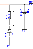
If I am not mistaken, isn't this the bleeding resistor in parallel with the cap ?
Why is there a reverse diode ? Won't this block the current from passing from the + terminal of the capacitor to the resistor then to gnd ? -
If I am not mistaken, isn't this the bleeding resistor in parallel with the cap ?
Why is there a reverse diode ? Won't this block the current from passing from the + terminal of the capacitor to the resistor then to gnd ?@ahmedadelhosni
It's a zener diode which will pass current once voltage is above 24v and then the resistor protects it from complete shorting to ground. -
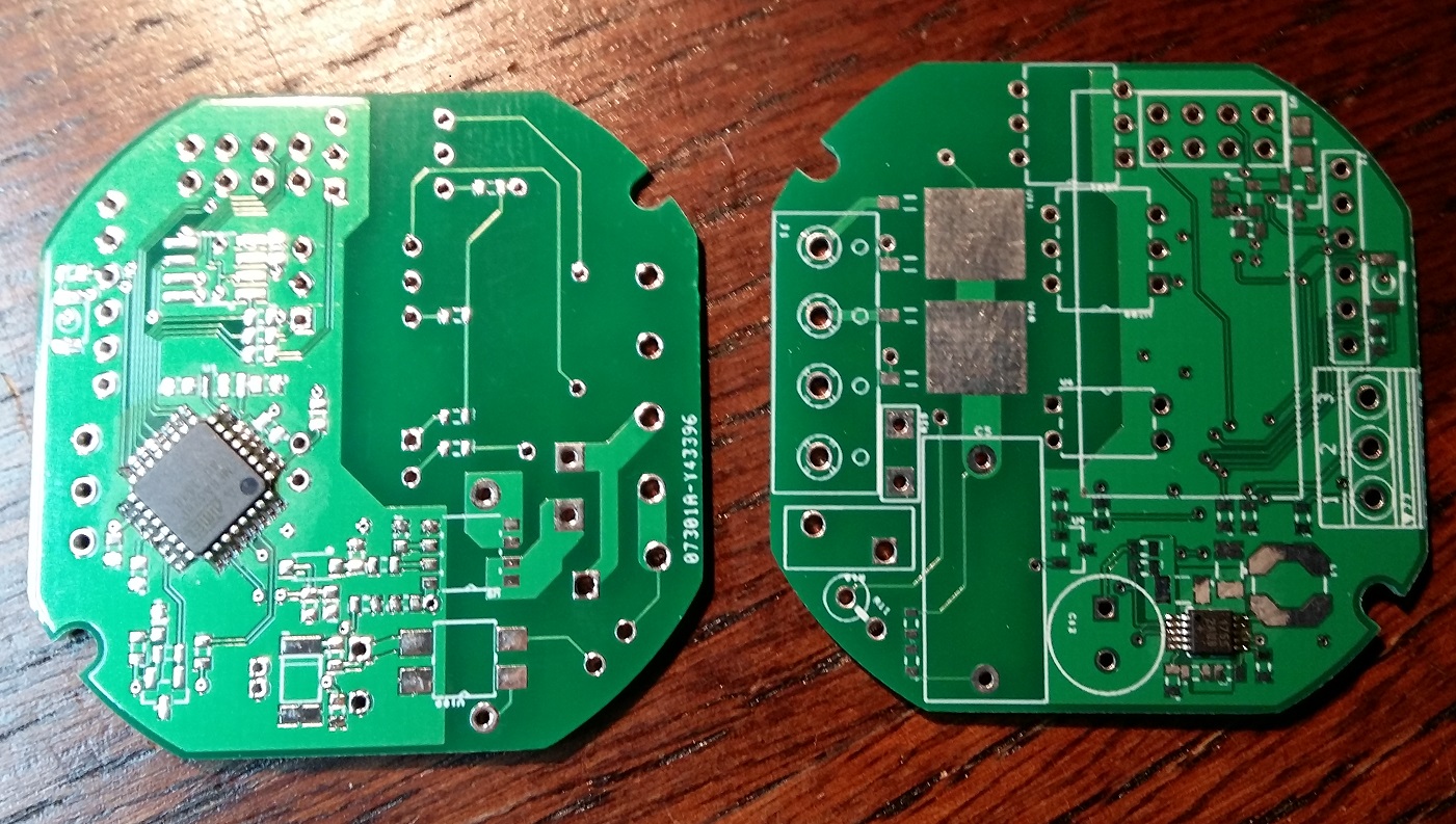
First components added after a visit to the lab at work and some soldering under the microscope
-
Hi just wanted to get an update on this project.
I have assembled 2 pcb (not all components) to start debug the processor platform and surroundings. Unfortunatly i got a bit stuck as i have problems loading the boot loader. I have tried to use the process suggested on arduino.cc using an nano as ISP. I get alot of strange behaviours and are not able to upload.Any tips and tricks is well received if you have any.
Othervise i will rest this project for a couple of weeks to be able to finnish my other thermostat project as well start a new, as the pool season is around the corner. And i really would love to be able to corntol pupm, lghts read temperatures and other stuff.
But if i find some good tricks i will pursue the goal to finnish this in wall dimmer before summer.
-
@Oitzu - why should not burning a bootloader to the atmega work without the nrf24 attached?
-
@sundberg84 in most of my cases it failed due to spi interferences.
-
@Oitzu Ahh, sorry I missunderstood you - the other way around. I read it like you had to have the nrf attached to make it work :)
![0_1458579519569_20160321_172537 [297989] (2).jpg](/uploads/files/1458579517358-20160321_172537-297989-2.jpg)