💬 Easy/Newbie PCB for MySensors
-
@rchamp - sorry for later reply, the mounting holes are 2mm or 78.7mil.
@sundberg84
awesome thanks! -
Hello, I ordered a second batch from PCBWay, it's ok except some components have a frame on the silkscreen, not very beautiful.
Just wanted to say that it was a pain to cut the 1.6mm PCB so this time I ordered in 0.8mm and it is sooooo easy to cut with regular cissors: no efforts and very clean cut ! So if you plan to cut the right part, order at 1mm or below, you will enjoy the cutting phase :D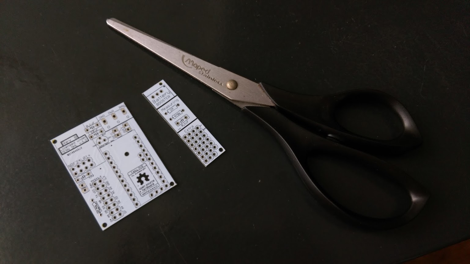
-
Hello, I ordered a second batch from PCBWay, it's ok except some components have a frame on the silkscreen, not very beautiful.
Just wanted to say that it was a pain to cut the 1.6mm PCB so this time I ordered in 0.8mm and it is sooooo easy to cut with regular cissors: no efforts and very clean cut ! So if you plan to cut the right part, order at 1mm or below, you will enjoy the cutting phase :D@Nca78 said:
it's ok except some components have a frame on the silkscreen, not very beautiful.
Sorry, I dont understand what you mean - can you give me a closeup photo? It should be functional AND beautiful :) If the silkscreen overlaps the copper parts this could interfer as well...
you will enjoy the cutting phase
I also learned it the hard way - and since there isnt any high power ciciut it should be ok to order very thin pcbs.
I used a metallic saw for one :persevere: and for some i cut a trace with a knife and bended it until it cracked. -
Just ordered 10 white bords, they look so great :)
-
@Nca78 said:
it's ok except some components have a frame on the silkscreen, not very beautiful.
Sorry, I dont understand what you mean - can you give me a closeup photo? It should be functional AND beautiful :) If the silkscreen overlaps the copper parts this could interfer as well...
you will enjoy the cutting phase
I also learned it the hard way - and since there isnt any high power ciciut it should be ok to order very thin pcbs.
I used a metallic saw for one :persevere: and for some i cut a trace with a knife and bended it until it cracked.@sundberg84 said:
Sorry, I dont understand what you mean - can you give me a closeup photo? It should be functional AND beautiful :) If the silkscreen overlaps the copper parts this could interfer as well...
I fact it's the case only for the "Rev B" and licence text at the top left. No big deal but it was looking better without the frame from DirtyPCB
I also learned it the hard way - and since there isnt any high power ciciut it should be ok to order very thin pcbs.
I used a metallic saw for one :persevere: and for some i cut a trace with a knife and bended it until it cracked.I used the knife too (don't have a metal saw) with the 1.6mm PCBs and it was long and messy. Now it's just like a strong cardboard.
-
I ordered some via DirtyPCB - Ordering via OpenHardware it seems to suggest you are buying Rev4. Says Rev4 under the order button at least.
@Qu3Uk - Yes, and its missleading. Its rev 9 you are ordering but the fourth update on openhardware.io Its no problem ordering from there, I always update those gerber files first.
-
I just wanted to make some suggestions for this board for the possible next revision. I recently ordered a 10 pack (which when I got it ended up being an 11 pack... BONUS BOARD).
When I put together my first board there were some things that I noticed. First, the boards that I got are labeled as rev 8 boards, but there is one small difference from the one shown on the openhardware.io website.

The placement of the 4.7uf capacitor and the raw power connection holes next to the nRF24L01+ socket are reversed. The spot that you have for the 4.7uf capacitor for the nRF24L01+ radio module is just a bit too close to the nRF24 connector. It appears that the capacitor that you chose in your design software was for a ceramic type cap that has a wider hole spacing and is narrower. Choose one for an electrolytic cap and move it away from the nRF24 connector a bit more. This should give the closer hole spacing designed for a small electrolytic cap and leave enough room for it.Similarly the spot you have for the 10uf cap above the regulator appears to also be a design for a ceramic cap with the wider hole spacing. Selecting electrolytics for these should not only give you the correct hole spacing for the electrolytic, but it should also better mark where the negative lead of the cap needs to go on your silkscreen layer.
The other thing that I wish this had was pads for a SMT AMS1117 regulator. This could be placed in the space under the nRF24 radio or just under the pro mini. You could do this in conjunction with the TO92 style that you have currently placed. It would give the board a bit more flexibility for users. In my parts box, I only had the AMS1117 regulators and not the TO92 style. I have since ordered some of the TO92 style, but having the flexibility for either would have been nice.
Last but not least, it would be nice to have slightly larger corner mounting holes. I don't have many small screws that fit those holes, and I have none that would work with the standoffs that I use.
Other than those few things, it seems like a rock solid board. Thanks for the hard work.
Vera Plus running UI7 with MySensors, Sonoffs and 1-Wire devices
Visit my website for more Bits, Bytes and Ramblings from me: http://dan.bemowski.info/ -
I just wanted to make some suggestions for this board for the possible next revision. I recently ordered a 10 pack (which when I got it ended up being an 11 pack... BONUS BOARD).
When I put together my first board there were some things that I noticed. First, the boards that I got are labeled as rev 8 boards, but there is one small difference from the one shown on the openhardware.io website.
The placement of the 4.7uf capacitor and the raw power connection holes next to the nRF24L01+ socket are reversed. The spot that you have for the 4.7uf capacitor for the nRF24L01+ radio module is just a bit too close to the nRF24 connector. It appears that the capacitor that you chose in your design software was for a ceramic type cap that has a wider hole spacing and is narrower. Choose one for an electrolytic cap and move it away from the nRF24 connector a bit more. This should give the closer hole spacing designed for a small electrolytic cap and leave enough room for it.Similarly the spot you have for the 10uf cap above the regulator appears to also be a design for a ceramic cap with the wider hole spacing. Selecting electrolytics for these should not only give you the correct hole spacing for the electrolytic, but it should also better mark where the negative lead of the cap needs to go on your silkscreen layer.
The other thing that I wish this had was pads for a SMT AMS1117 regulator. This could be placed in the space under the nRF24 radio or just under the pro mini. You could do this in conjunction with the TO92 style that you have currently placed. It would give the board a bit more flexibility for users. In my parts box, I only had the AMS1117 regulators and not the TO92 style. I have since ordered some of the TO92 style, but having the flexibility for either would have been nice.
Last but not least, it would be nice to have slightly larger corner mounting holes. I don't have many small screws that fit those holes, and I have none that would work with the standoffs that I use.
Other than those few things, it seems like a rock solid board. Thanks for the hard work.
@dbemowsk - Hi!
Thank you for great input!Why the difference, is because I released rev 8 but made some last minute changes and forgot to update to rev 8.1.
You pretty much found the difference. It was a couple of days so I didnt think anybody would notice.
Did you order from DirtyPCB? I see not it got the old rev 8 version. I will update openhardware.io!Your suggestions about the 4,7uF cap is exactly what I did in the correct Rev 8 version.
I use electrolytic caps on both 4,7 0,1 and 10 uF without any problems. The G marks ground.I also like the AMS1117 but since its another design than LE33 and MySensors site wuggest LE33 i went with this.
Its a balance between flexibility and easy to use. To many components (like dual voltage regulators) will confuse some new users.I will try to fit in some bigger holes in rev 9 (currently working on it) and see what I can do about the AMS1117 .
Thank you for great input - ill keep it in mind!Br
Andreas -
Hi,
First of all, thank you @sundberg84 for this great PCB. Super easy to work with. Still; there is one question that I haven't been able to figure out yet.
I'm running my pcb as a battery node and want to monitor the battery status. However A0 always returns a value somewhere around 30 +/- 15 - even with brand new batteries. Calculated into voltage, this would mean around 1,04V.
I've checked and double checked that I'm using 470k and 1M resistors.
I've also measured using a multi meter, with incoming value of 3,2 V and outgoing from booster 3,36V.Any ideas that might point me in the right direction for solving this noob issue?
-
Hi,
First of all, thank you @sundberg84 for this great PCB. Super easy to work with. Still; there is one question that I haven't been able to figure out yet.
I'm running my pcb as a battery node and want to monitor the battery status. However A0 always returns a value somewhere around 30 +/- 15 - even with brand new batteries. Calculated into voltage, this would mean around 1,04V.
I've checked and double checked that I'm using 470k and 1M resistors.
I've also measured using a multi meter, with incoming value of 3,2 V and outgoing from booster 3,36V.Any ideas that might point me in the right direction for solving this noob issue?
@daand83 - do you mean analogread() always returns 30 but you still got 1,04V in? If so, either you have a bad connection to A0 or the chip is broken. I have had atmegas (pro mini) which was broken.
You could try soldering a second wire from A0 to the voltage divider to exclude connections errors. You could also measure the voltage input on the atmega chip. If its 1.04 there as well a bad connection can be excluded and you hav a bad pro mini / atmenga chip.
It coule be a code error as well, if you have changed to code...
Controller: Proxmox VM - Home Assistant
MySensors GW: Arduino Uno - W5100 Ethernet, Gw Shield Nrf24l01+ 2,4Ghz
MySensors GW: Arduino Uno - Gw Shield RFM69, 433mhz
RFLink GW - Arduino Mega + RFLink Shield, 433mhz -
@daand83 - do you mean analogread() always returns 30 but you still got 1,04V in? If so, either you have a bad connection to A0 or the chip is broken. I have had atmegas (pro mini) which was broken.
You could try soldering a second wire from A0 to the voltage divider to exclude connections errors. You could also measure the voltage input on the atmega chip. If its 1.04 there as well a bad connection can be excluded and you hav a bad pro mini / atmenga chip.
It coule be a code error as well, if you have changed to code...
@sundberg84
Hi,What I've done is this;
Measured voltage on PWR/GND which returns 3,2 V. I've measured voltage on GND/Vout on the battery booster which returns 3,36V. However, analogread always returns something like 300 +/-10, which (using the formula provided) indicates a voltage of 1,04 V and a battery percentage of ~30%. This has been the case with brand new batteries as well as old ones... -
@sundberg84
Hi,What I've done is this;
Measured voltage on PWR/GND which returns 3,2 V. I've measured voltage on GND/Vout on the battery booster which returns 3,36V. However, analogread always returns something like 300 +/-10, which (using the formula provided) indicates a voltage of 1,04 V and a battery percentage of ~30%. This has been the case with brand new batteries as well as old ones...@daand83 - this is quite dependent on which code you use I think but it sounds right. A return of 1000 would be 3,3V in my code.
This is my code:
Defines:
//=========================
// BATTERY VOLTAGE DIVIDER SETUP
// 1M, 470K divider across battery and using internal ADC ref of 1.1V
// Sense point is bypassed with 0.1 uF cap to reduce noise at that point
// ((1e6+470e3)/470e3)*1.1 = Vmax = 3.44 Volts
// 3.44/1023 = Volts per bit = 0.003363075
#define VBAT_PER_BITS 0.003363075
#define VMIN 1.9                         //  Vmin (radio Min Volt)=1.9V (564)
#define VMAX 3.0                        //  Vmax = (2xAA bat)=3.0V (892)
int batteryPcnt = 0;                       // Calc value for battery %
int BATTERY_SENSE_PIN = A0; // select the input pin for the battery sense point
//=========================
Setup()
analogReference(INTERNAL); // For battery sensingLoop()
delay(500);
   // Battery monitoring reading
   int sensorValue = analogRead(BATTERY_SENSE_PIN);
   delay(500);

   // Calculate the battery in %
   float Vbat  = sensorValue * VBAT_PER_BITS;
   int batteryPcnt = static_cast<int>(((Vbat-VMIN)/(VMAX-VMIN))*100.);
Serial.print("Battery percent: ");
Serial.print(batteryPcnt);
Serial.println(" %");

if (batteryPcnt > 100) {
     batteryPcnt=100;
 }

Serial.print(batteryPcnt);
Serial.println(" %");
gw.sendBatteryLevel(batteryPcnt);
I think you should measure the voltage on A0 to Gnd and see what you get.
Controller: Proxmox VM - Home Assistant
MySensors GW: Arduino Uno - W5100 Ethernet, Gw Shield Nrf24l01+ 2,4Ghz
MySensors GW: Arduino Uno - Gw Shield RFM69, 433mhz
RFLink GW - Arduino Mega + RFLink Shield, 433mhz -
@daand83 - this is quite dependent on which code you use I think but it sounds right. A return of 1000 would be 3,3V in my code.
This is my code:
Defines:
//=========================
// BATTERY VOLTAGE DIVIDER SETUP
// 1M, 470K divider across battery and using internal ADC ref of 1.1V
// Sense point is bypassed with 0.1 uF cap to reduce noise at that point
// ((1e6+470e3)/470e3)*1.1 = Vmax = 3.44 Volts
// 3.44/1023 = Volts per bit = 0.003363075
#define VBAT_PER_BITS 0.003363075
#define VMIN 1.9                         //  Vmin (radio Min Volt)=1.9V (564)
#define VMAX 3.0                        //  Vmax = (2xAA bat)=3.0V (892)
int batteryPcnt = 0;                       // Calc value for battery %
int BATTERY_SENSE_PIN = A0; // select the input pin for the battery sense point
//=========================
Setup()
analogReference(INTERNAL); // For battery sensingLoop()
delay(500);
   // Battery monitoring reading
   int sensorValue = analogRead(BATTERY_SENSE_PIN);
   delay(500);

   // Calculate the battery in %
   float Vbat  = sensorValue * VBAT_PER_BITS;
   int batteryPcnt = static_cast<int>(((Vbat-VMIN)/(VMAX-VMIN))*100.);
Serial.print("Battery percent: ");
Serial.print(batteryPcnt);
Serial.println(" %");

if (batteryPcnt > 100) {
     batteryPcnt=100;
 }

Serial.print(batteryPcnt);
Serial.println(" %");
gw.sendBatteryLevel(batteryPcnt);
I think you should measure the voltage on A0 to Gnd and see what you get.
@sundberg84 - the only weird part is that analogread() returns a value of 300, which in turn is below VMIN; and hence a negative value (1,04-1,9)/(3,0-1,9) = -78%.
But if I understand you correctly the next two steps in the troubleshooting process would be;
- measure GND/VCC on the atmega-chip as well to make sure that it is indeed not a faulty chip?
- solder a second connection from A0 to the voltage divider to remove any bad connections
Thanks again :) :+1:
-
@sundberg84 - the only weird part is that analogread() returns a value of 300, which in turn is below VMIN; and hence a negative value (1,04-1,9)/(3,0-1,9) = -78%.
But if I understand you correctly the next two steps in the troubleshooting process would be;
- measure GND/VCC on the atmega-chip as well to make sure that it is indeed not a faulty chip?
- solder a second connection from A0 to the voltage divider to remove any bad connections
Thanks again :) :+1:
I have to verify when I get home, but I've probably found the problem... Seems as a stupid copy/paste problem. No call to analogreference(INTERNAL). Don't know how I've been able to overlook this for a week now, but... Will check back with result later on...
-
I have to verify when I get home, but I've probably found the problem... Seems as a stupid copy/paste problem. No call to analogreference(INTERNAL). Don't know how I've been able to overlook this for a week now, but... Will check back with result later on...
@daand83 - haha, easy to forget - I also forgot to post in in my example above (changed now) :)
Only one line of code in a different place... well, hope you found it!Controller: Proxmox VM - Home Assistant
MySensors GW: Arduino Uno - W5100 Ethernet, Gw Shield Nrf24l01+ 2,4Ghz
MySensors GW: Arduino Uno - Gw Shield RFM69, 433mhz
RFLink GW - Arduino Mega + RFLink Shield, 433mhz -
@daand83 - haha, easy to forget - I also forgot to post in in my example above (changed now) :)
Only one line of code in a different place... well, hope you found it!@sundberg84 - Indeed missing analogreference. All good now, even got a battery value of 102 % ;)
-
@sundberg84 said:
AMS1117
mmmm I would like to see a board with room for AMS1117 and caps... :)
While waiting for my Newbie PCBs to arrive I have built my own test sensor on a bit of breadboard. Got the new 0,8-3.3v to 3.3v today. My boosters. So, I just cut the trace going from the battery to the rest of the components and arduino and there I connected my booster. VIN directly from bat + and gnd from bat -, Also, everything else that need GND is connected to the same place. I then reconnected the plus power rail to the power coming from the booster. I also moved the radio connection so that if feed directly from the battery. Measurements show me 3.3 v to arduino and other sensors and about 2.9 to the radio directly from batt. Something does not want to work. It is something with the power to the radio. Running sensor on battery only, no booster, works just fine. Running node with everything on vout from the booster, it just won't work. The radio struggles to do something useful but it fails. Running radio on batt and the rest on booster does not work. 'But, if I power the node with power from the serial adapter. the node woks again but only if the battery provide power to the radio at the same time.
Any suggestions? Quite tired, can be messy ;)
@NiklasO - do you have any serial log?
2,9V should be just fine for the radio, but it might freeze with spikes from booster or other power circuit. A 0,1cap from Out to Gnd on the booster might help.Try to remove the booster and verify if the radio works then - if so, its the booster. If not try another radio - we know the radios is very different quality sometimes.
-
Hello, I think @sundberg84 is right, you need some capacitors to filter the noise from the booster, the best is to put the same than those that are on EasyPCB (top of the voltage regulator).
Even if you power the radio directly from the battery, the booster will generate some noise if you use it to power the board, as they have the same GND.