Skip to content
  • MySensors
  • OpenHardware.io
  • Categories
  • Recent
  • Tags
  • Popular
Skins
  • Light
  • Brite
  • Cerulean
  • Cosmo
  • Flatly
  • Journal
  • Litera
  • Lumen
  • Lux
  • Materia
  • Minty
  • Morph
  • Pulse
  • Sandstone
  • Simplex
  • Sketchy
  • Spacelab
  • United
  • Yeti
  • Zephyr
  • Dark
  • Cyborg
  • Darkly
  • Quartz
  • Slate
  • Solar
  • Superhero
  • Vapor

  • Default (No Skin)
  • No Skin
Collapse
Brand Logo
  1. Home
  2. OpenHardware.io
  3. ๐Ÿ’ฌ Easy/Newbie PCB for MySensors

๐Ÿ’ฌ Easy/Newbie PCB for MySensors

Scheduled Pinned Locked Moved OpenHardware.io
mysensorsbatteryeasynewbiepcbmysx
716 Posts 111 Posters 306.2k Views 93 Watching
  • Oldest to Newest
  • Newest to Oldest
  • Most Votes
Reply
  • Reply as topic
Log in to reply
This topic has been deleted. Only users with topic management privileges can see it.
  • dbemowskD dbemowsk

    So I have one more flaw to point out in the board that I didn't notice before. I also have a question regarding powering the nano. I'll start with the problem and this is for @sundberg84 . Some weeks back I posted some suggestions and differences that I noticed in the revisions of the boards. This was the pic:
    alt text
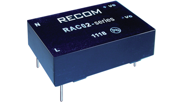
    When I posted that, you noted that for the capacitors, the G denotes ground. If you look at the blue board on the right which is the one that I have, you have the G marked on the left leg of the capacitor. If you measure continuity from that pin to the large ground tab for incoming power, you will notice that that is not ground. The one on the right is. Since I got the boards, I have always teeted for continuity for my ground legs, so I haven't had any issues, but for a newbie, which is what the board is geared toward, there could be issues.

    Now on to my question regarding power. So I am building another node and I am using the 5 volt version of a Recom power module alt text.
    Seeing that this is a 5 volt output, I would think I should be able to go directly to the 5 volt in on the nano, but what is the best way to wire this if I am using a screw terminal connector to bring my power in? The RAW power pad goes to the regulator input on the nano, and the PWR pad goes to the battery booster which I am not using. I would also guess that I would need to jumper the BAT pads. Would I then too want to remove the regulator from the nano, or won't that matter?

    Any help is appreciated.

    sundberg84S Offline
    sundberg84S Offline
    sundberg84
    Hardware Contributor
    wrote on last edited by sundberg84
    #198

    @dbemowsk - thanks for your unput! I have checked my project and changed the G label.
    I will also make an notise on openhardware!

    You should be able to use that just fine as power. Most people here use HLK-PM01 but this might be a great addition! (Havent seen it before).
    Check this thread out: https://forum.mysensors.org/topic/1607/safe-in-wall-ac-to-dc-transformers. You should connect it to PWR and GND with REG jumper short.

    Controller: Proxmox VM - Home Assistant
    MySensors GW: Arduino Uno - W5100 Ethernet, Gw Shield Nrf24l01+ 2,4Ghz
    MySensors GW: Arduino Uno - Gw Shield RFM69, 433mhz
    RFLink GW - Arduino Mega + RFLink Shield, 433mhz

    Nca78N 1 Reply Last reply
    0
    • sundberg84S sundberg84

      @dbemowsk - thanks for your unput! I have checked my project and changed the G label.
      I will also make an notise on openhardware!

      You should be able to use that just fine as power. Most people here use HLK-PM01 but this might be a great addition! (Havent seen it before).
      Check this thread out: https://forum.mysensors.org/topic/1607/safe-in-wall-ac-to-dc-transformers. You should connect it to PWR and GND with REG jumper short.

      Nca78N Offline
      Nca78N Offline
      Nca78
      Hardware Contributor
      wrote on last edited by
      #199

      @sundberg84 said:
      this might be a great addition! (Havent seen it before).

      Unfortunately it's not the same price range as HLK with 12$95 from all suppliers linked from their website.
      Could still have been nice if it had "physical" advantages compared to HLK but it's bigger and with lower power.
      So it's got the safety of a German product left, but HLK is safe enough provided we get a genuine one.

      Interesting part is the recommended circuit which is similar to the one suggested here for the HLK with input fuse, varistor for use with 230V source and optionnal output capacitor to reduce ripple. No temperature fuse but I suppose with bigger size, lower power and higher quality components it's getting really overkill.

      1 Reply Last reply
      0
      • dbemowskD Offline
        dbemowskD Offline
        dbemowsk
        wrote on last edited by
        #200

        I ended up ordering 3 of these. I got them from this site. It wasn't till after I ordered them that I saw a post on here about the HLK-PM01 modules. I see the better advantages of the HLK series, cost being the big one, and will order these in the future as needed, but I am just trying to use up the 3 of these that I have.

        I have another project I am working on where I might order some HLK-PM12 modules. I ended up getting a lot of 10 - 12 or 24 volt relay modules for free that I figure I can use in some projects. I wish they were 5 volt, but it's hard to argue with FREE.

        Vera Plus running UI7 with MySensors, Sonoffs and 1-Wire devices
        Visit my website for more Bits, Bytes and Ramblings from me: http://dan.bemowski.info/

        1 Reply Last reply
        0
        • fabix68F Offline
          fabix68F Offline
          fabix68
          wrote on last edited by
          #201

          Hello,
          I'm using the temperature sensor (DS18B20) on a card v8.
          Ok if I use a 18650 battery, if I use a CR2032 coin battery, the sensor does not work.
          I have to make some adjustments?

          1 Reply Last reply
          0
          • dbemowskD Offline
            dbemowskD Offline
            dbemowsk
            wrote on last edited by
            #202

            @fabix68 Your problem might be in the fact that the 18650 battery is a 3.7 volt battery, where the CR2032 is only a 3 volt. The extra 0.7 volts will make all the difference. If you use a CR2032, there are a few things you want to do. The first thing is that you need a battery booster. This will boost your power from 3 volts to the needed 3.3 for the nano and the radio. Next is to remove the LED from your nano. This will put unnecessary load on your battery and drain it much faster. You may even want to remove the regulator from the nano.

            Vera Plus running UI7 with MySensors, Sonoffs and 1-Wire devices
            Visit my website for more Bits, Bytes and Ramblings from me: http://dan.bemowski.info/

            1 Reply Last reply
            1
            • fabix68F Offline
              fabix68F Offline
              fabix68
              wrote on last edited by
              #203

              I'm already using a booster to the battery and removed led and regulator. I partially solved by inserting in parallel to battery a 10mF capacitor

              1 Reply Last reply
              0
              • sundberg84S Offline
                sundberg84S Offline
                sundberg84
                Hardware Contributor
                wrote on last edited by
                #204

                What are your setup @fabix68 ? If you are using a 3.3v arudino straight on it will not work.
                Please describe your setup and hardware and not only your battery,

                Controller: Proxmox VM - Home Assistant
                MySensors GW: Arduino Uno - W5100 Ethernet, Gw Shield Nrf24l01+ 2,4Ghz
                MySensors GW: Arduino Uno - Gw Shield RFM69, 433mhz
                RFLink GW - Arduino Mega + RFLink Shield, 433mhz

                1 Reply Last reply
                0
                • fabix68F Offline
                  fabix68F Offline
                  fabix68
                  wrote on last edited by fabix68
                  #205

                  I'm using Arduino mini pro 3.3v to which I removed led and regulator, battery boster and tamper on batt.
                  I attach the photo
                  alt text

                  sundberg84S 1 Reply Last reply
                  0
                  • fabix68F fabix68

                    I'm using Arduino mini pro 3.3v to which I removed led and regulator, battery boster and tamper on batt.
                    I attach the photo
                    alt text

                    sundberg84S Offline
                    sundberg84S Offline
                    sundberg84
                    Hardware Contributor
                    wrote on last edited by
                    #206

                    @fabix68 should work just fine.
                    Whats your issue? Any serial output?

                    Controller: Proxmox VM - Home Assistant
                    MySensors GW: Arduino Uno - W5100 Ethernet, Gw Shield Nrf24l01+ 2,4Ghz
                    MySensors GW: Arduino Uno - Gw Shield RFM69, 433mhz
                    RFLink GW - Arduino Mega + RFLink Shield, 433mhz

                    1 Reply Last reply
                    0
                    • fabix68F Offline
                      fabix68F Offline
                      fabix68
                      wrote on last edited by
                      #207

                      Now, with the capacitor on the VCC, it seems to work, even if the range is smaller. It will be to evaluate the battery life

                      1 Reply Last reply
                      0
                      • Nca78N Offline
                        Nca78N Offline
                        Nca78
                        Hardware Contributor
                        wrote on last edited by
                        #208

                        Hello, don't waste your CR2032 yet, as it is now you will be lucky to last a few days ...

                        CR2032 and other lithium cells with the same chemistry have a strong internal resistance. It means the more current you draw from them, the more energy you will waste because of this internal resistance. It makes the voltage drop and it means your battery booster will need more and more current to maintain the output voltage = vicious circle with more and more energy wasted.

                        Your solution is not to add a battery booster but to use another sensor that will be able to run at low voltage: BMP180/BMP280/BME280 or SHT21/SI7021. They have a very low power consumption (unlike ds18) and will accept Vcc voltage below 2V. I would suggest the SHT21/SI7021 as it's easier to use and will go in sleep mode between measurements without any action from you.

                        Without battery booster you will also have a much increased range as the booster generates a lot of noise that perturbates the radio.
                        You will also need to:

                        • add a big capacitor (at least 100ยตF) in parallel with the battery to ease out the current peaks
                        • remove the voltage regulator as it's still on your pro mini at the moment
                        • adapt your sketch to sleep (with 200ms you should be ok) between all consecutive radio calls. Don't forget to do it in the presentation method as it's the most sensible part, before it's called the library has already done many radio calls that made your battery voltage drop. You should begin the presentation method with a sleep.
                        • update the fuses on your pro mini to remove the BOD which is by default at 2.7V and will limit the total power you will get from the battery
                        • use a brand name cell, the cheap chinese no-name cells will have much lower real capacity available, voltage will drop much faster.
                        1 Reply Last reply
                        1
                        • fabix68F Offline
                          fabix68F Offline
                          fabix68
                          wrote on last edited by
                          #209

                          @Nca78 said:

                          SHT21

                          Nca78 thanks for the reply.
                          I did not know the SHT21 sensor, it looks like a good alternative also DHT22.
                          I've already added a capacitor and view the trace output with the oscilloscope, it is clean, why not explain the decrease in range.
                          With regard to the program, has been provided for the sending of data every 5 minutes, if it changes from the previous value, to then return to sleep.
                          I never tried to change the fuse on the PRO. I believe that this is the solution. Run it at minimum frequency, remove the BDO so you can also remove the battery booster.

                          1 Reply Last reply
                          0
                          • dbemowskD Offline
                            dbemowskD Offline
                            dbemowsk
                            wrote on last edited by
                            #210

                            I am wondering on the Rev 8 boards how much room there is around the outer mounting holes to drill them a bit larger? Is this just a dual layer board or are there other sandwiched layers in it that might be affected if I drill them larger?I have been trying to find a decent way to mount these and stack them with other boards, but I'm not having much luck. The project I am working on right now is a revised board for my garage door controller and I have my power supply circuit on a piece of proto board and I want to stack the newbie PCB on top of it, but can't find standoffs that small, and I am having real trouble even finding screws that will fit the holes. Has anyone done mounting of these? If I can find screws and mounting hardware that will work without having to drill the holes bigger I am all for it.

                            Vera Plus running UI7 with MySensors, Sonoffs and 1-Wire devices
                            Visit my website for more Bits, Bytes and Ramblings from me: http://dan.bemowski.info/

                            sundberg84S 1 Reply Last reply
                            0
                            • dbemowskD dbemowsk

                              I am wondering on the Rev 8 boards how much room there is around the outer mounting holes to drill them a bit larger? Is this just a dual layer board or are there other sandwiched layers in it that might be affected if I drill them larger?I have been trying to find a decent way to mount these and stack them with other boards, but I'm not having much luck. The project I am working on right now is a revised board for my garage door controller and I have my power supply circuit on a piece of proto board and I want to stack the newbie PCB on top of it, but can't find standoffs that small, and I am having real trouble even finding screws that will fit the holes. Has anyone done mounting of these? If I can find screws and mounting hardware that will work without having to drill the holes bigger I am all for it.

                              sundberg84S Offline
                              sundberg84S Offline
                              sundberg84
                              Hardware Contributor
                              wrote on last edited by
                              #211

                              @dbemowsk said:

                              I am wondering on the Rev 8 boards how much room there is around the outer mounting holes to drill them a bit larger? Is this just a dual layer board or are there other sandwiched layers.

                              Its a dual board - drill as much as you want, you can see all traces. In my upcoming rev the holes are bigger. I have recieved this feedback and are improving this.

                              Controller: Proxmox VM - Home Assistant
                              MySensors GW: Arduino Uno - W5100 Ethernet, Gw Shield Nrf24l01+ 2,4Ghz
                              MySensors GW: Arduino Uno - Gw Shield RFM69, 433mhz
                              RFLink GW - Arduino Mega + RFLink Shield, 433mhz

                              Lior RubinL 1 Reply Last reply
                              0
                              • sundberg84S sundberg84

                                @dbemowsk said:

                                I am wondering on the Rev 8 boards how much room there is around the outer mounting holes to drill them a bit larger? Is this just a dual layer board or are there other sandwiched layers.

                                Its a dual board - drill as much as you want, you can see all traces. In my upcoming rev the holes are bigger. I have recieved this feedback and are improving this.

                                Lior RubinL Offline
                                Lior RubinL Offline
                                Lior Rubin
                                wrote on last edited by
                                #212

                                @sundberg84 said:

                                In my upcoming rev the holes are bigger. I have recieved this feedback and are improving this.

                                what should be on the next rev ?

                                sundberg84S 1 Reply Last reply
                                0
                                • Lior RubinL Lior Rubin

                                  @sundberg84 said:

                                  In my upcoming rev the holes are bigger. I have recieved this feedback and are improving this.

                                  what should be on the next rev ?

                                  sundberg84S Offline
                                  sundberg84S Offline
                                  sundberg84
                                  Hardware Contributor
                                  wrote on last edited by
                                  #213

                                  @Lior-Rubin Changelog so far:

                                  • Bigger mounting holes 2.5mm
                                  • IRQ Jumper from Radio. This makes this trace disabled and D2 can be used for interupts unless jumper is connected.
                                  • BAT and REG jumpers changed positions for better tracing.
                                  • MysX 2,6
                                  • Text on voltage regulater (Vout/Vin/Gnd)
                                  • Bug with G on CAP now on the right side.

                                  Release and if there will be more things added I dont know.
                                  Any suggestions?

                                  Controller: Proxmox VM - Home Assistant
                                  MySensors GW: Arduino Uno - W5100 Ethernet, Gw Shield Nrf24l01+ 2,4Ghz
                                  MySensors GW: Arduino Uno - Gw Shield RFM69, 433mhz
                                  RFLink GW - Arduino Mega + RFLink Shield, 433mhz

                                  Q 1 Reply Last reply
                                  1
                                  • sundberg84S sundberg84

                                    @Lior-Rubin Changelog so far:

                                    • Bigger mounting holes 2.5mm
                                    • IRQ Jumper from Radio. This makes this trace disabled and D2 can be used for interupts unless jumper is connected.
                                    • BAT and REG jumpers changed positions for better tracing.
                                    • MysX 2,6
                                    • Text on voltage regulater (Vout/Vin/Gnd)
                                    • Bug with G on CAP now on the right side.

                                    Release and if there will be more things added I dont know.
                                    Any suggestions?

                                    Q Offline
                                    Q Offline
                                    Qu3Uk
                                    wrote on last edited by
                                    #214

                                    @sundberg84

                                    In power input I would suggest moving GND to the middle of VCC/RAW so you could using a 2 pin block for GND/RAW like what is shown in post 205. Might cause tracing issues though for you.

                                    sundberg84S 1 Reply Last reply
                                    0
                                    • Q Qu3Uk

                                      @sundberg84

                                      In power input I would suggest moving GND to the middle of VCC/RAW so you could using a 2 pin block for GND/RAW like what is shown in post 205. Might cause tracing issues though for you.

                                      sundberg84S Offline
                                      sundberg84S Offline
                                      sundberg84
                                      Hardware Contributor
                                      wrote on last edited by
                                      #215

                                      @Qu3Uk - its a good suggestion.
                                      I will se what I can do.

                                      Controller: Proxmox VM - Home Assistant
                                      MySensors GW: Arduino Uno - W5100 Ethernet, Gw Shield Nrf24l01+ 2,4Ghz
                                      MySensors GW: Arduino Uno - Gw Shield RFM69, 433mhz
                                      RFLink GW - Arduino Mega + RFLink Shield, 433mhz

                                      1 Reply Last reply
                                      0
                                      • Lior RubinL Offline
                                        Lior RubinL Offline
                                        Lior Rubin
                                        wrote on last edited by
                                        #216

                                        @sundberg84 I may suggest the following:

                                        • place for Temp\Hum sensor
                                        • place for Light sensor
                                        • ability to use AC to DC (3\5v) in the board
                                        • ESP8266 option rather than Arduino (maybe 2 versions)
                                        • TX\RX connection or FTDI connection
                                        1 Reply Last reply
                                        0
                                        • dbemowskD Offline
                                          dbemowskD Offline
                                          dbemowsk
                                          wrote on last edited by
                                          #217

                                          I had mentioned this before, but the electrolytic capacitors wer put in the design using a ceramic capacitor designation which doesn't allow room for correct placement of capacitors. The main one is the one near the radio. The pads for the cap are spaced too far apart for a small electrolytic, and they are too close to the connector requiring that the capacitor leads be bent toward the radio connector to be able to get it to fit.

                                          Vera Plus running UI7 with MySensors, Sonoffs and 1-Wire devices
                                          Visit my website for more Bits, Bytes and Ramblings from me: http://dan.bemowski.info/

                                          1 Reply Last reply
                                          2
                                          Reply
                                          • Reply as topic
                                          Log in to reply
                                          • Oldest to Newest
                                          • Newest to Oldest
                                          • Most Votes


                                          25

                                          Online

                                          11.7k

                                          Users

                                          11.2k

                                          Topics

                                          113.0k

                                          Posts


                                          Copyright 2019 TBD   |   Forum Guidelines   |   Privacy Policy   |   Terms of Service
                                          • Login

                                          • Don't have an account? Register

                                          • Login or register to search.
                                          • First post
                                            Last post
                                          0
                                          • MySensors
                                          • OpenHardware.io
                                          • Categories
                                          • Recent
                                          • Tags
                                          • Popular