Skip to content
  • MySensors
  • OpenHardware.io
  • Categories
  • Recent
  • Tags
  • Popular
Skins
  • Light
  • Brite
  • Cerulean
  • Cosmo
  • Flatly
  • Journal
  • Litera
  • Lumen
  • Lux
  • Materia
  • Minty
  • Morph
  • Pulse
  • Sandstone
  • Simplex
  • Sketchy
  • Spacelab
  • United
  • Yeti
  • Zephyr
  • Dark
  • Cyborg
  • Darkly
  • Quartz
  • Slate
  • Solar
  • Superhero
  • Vapor

  • Default (No Skin)
  • No Skin
Collapse
Brand Logo
  1. Home
  2. OpenHardware.io
  3. 💬 Easy/Newbie PCB for MySensors

💬 Easy/Newbie PCB for MySensors

Scheduled Pinned Locked Moved OpenHardware.io
mysensorsbatteryeasynewbiepcbmysx
716 Posts 111 Posters 306.2k Views 93 Watching
  • Oldest to Newest
  • Newest to Oldest
  • Most Votes
Reply
  • Reply as topic
Log in to reply
This topic has been deleted. Only users with topic management privileges can see it.
  • Lior RubinL Lior Rubin

    @sundberg84 said:

    In my upcoming rev the holes are bigger. I have recieved this feedback and are improving this.

    what should be on the next rev ?

    sundberg84S Offline
    sundberg84S Offline
    sundberg84
    Hardware Contributor
    wrote on last edited by
    #213

    @Lior-Rubin Changelog so far:

    • Bigger mounting holes 2.5mm
    • IRQ Jumper from Radio. This makes this trace disabled and D2 can be used for interupts unless jumper is connected.
    • BAT and REG jumpers changed positions for better tracing.
    • MysX 2,6
    • Text on voltage regulater (Vout/Vin/Gnd)
    • Bug with G on CAP now on the right side.

    Release and if there will be more things added I dont know.
    Any suggestions?

    Controller: Proxmox VM - Home Assistant
    MySensors GW: Arduino Uno - W5100 Ethernet, Gw Shield Nrf24l01+ 2,4Ghz
    MySensors GW: Arduino Uno - Gw Shield RFM69, 433mhz
    RFLink GW - Arduino Mega + RFLink Shield, 433mhz

    Q 1 Reply Last reply
    1
    • sundberg84S sundberg84

      @Lior-Rubin Changelog so far:

      • Bigger mounting holes 2.5mm
      • IRQ Jumper from Radio. This makes this trace disabled and D2 can be used for interupts unless jumper is connected.
      • BAT and REG jumpers changed positions for better tracing.
      • MysX 2,6
      • Text on voltage regulater (Vout/Vin/Gnd)
      • Bug with G on CAP now on the right side.

      Release and if there will be more things added I dont know.
      Any suggestions?

      Q Offline
      Q Offline
      Qu3Uk
      wrote on last edited by
      #214

      @sundberg84

      In power input I would suggest moving GND to the middle of VCC/RAW so you could using a 2 pin block for GND/RAW like what is shown in post 205. Might cause tracing issues though for you.

      sundberg84S 1 Reply Last reply
      0
      • Q Qu3Uk

        @sundberg84

        In power input I would suggest moving GND to the middle of VCC/RAW so you could using a 2 pin block for GND/RAW like what is shown in post 205. Might cause tracing issues though for you.

        sundberg84S Offline
        sundberg84S Offline
        sundberg84
        Hardware Contributor
        wrote on last edited by
        #215

        @Qu3Uk - its a good suggestion.
        I will se what I can do.

        Controller: Proxmox VM - Home Assistant
        MySensors GW: Arduino Uno - W5100 Ethernet, Gw Shield Nrf24l01+ 2,4Ghz
        MySensors GW: Arduino Uno - Gw Shield RFM69, 433mhz
        RFLink GW - Arduino Mega + RFLink Shield, 433mhz

        1 Reply Last reply
        0
        • Lior RubinL Offline
          Lior RubinL Offline
          Lior Rubin
          wrote on last edited by
          #216

          @sundberg84 I may suggest the following:

          • place for Temp\Hum sensor
          • place for Light sensor
          • ability to use AC to DC (3\5v) in the board
          • ESP8266 option rather than Arduino (maybe 2 versions)
          • TX\RX connection or FTDI connection
          1 Reply Last reply
          0
          • dbemowskD Offline
            dbemowskD Offline
            dbemowsk
            wrote on last edited by
            #217

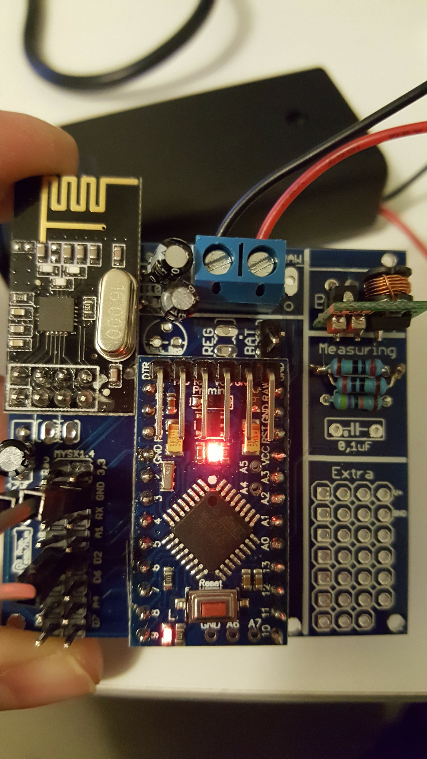
            I had mentioned this before, but the electrolytic capacitors wer put in the design using a ceramic capacitor designation which doesn't allow room for correct placement of capacitors. The main one is the one near the radio. The pads for the cap are spaced too far apart for a small electrolytic, and they are too close to the connector requiring that the capacitor leads be bent toward the radio connector to be able to get it to fit.

            Vera Plus running UI7 with MySensors, Sonoffs and 1-Wire devices
            Visit my website for more Bits, Bytes and Ramblings from me: http://dan.bemowski.info/

            1 Reply Last reply
            2
            • sundberg84S Offline
              sundberg84S Offline
              sundberg84
              Hardware Contributor
              wrote on last edited by
              #218

              @Lior-Rubin @dbemowsk - thanks you for the suggestions. I will take them into consideration!

              Im not sure I will implement everything because the main purpose of this PCB is to keep it SIMPLE. Its a newbie/easy PCB and to many components and/or other things will make it hard for new members to use.

              Controller: Proxmox VM - Home Assistant
              MySensors GW: Arduino Uno - W5100 Ethernet, Gw Shield Nrf24l01+ 2,4Ghz
              MySensors GW: Arduino Uno - Gw Shield RFM69, 433mhz
              RFLink GW - Arduino Mega + RFLink Shield, 433mhz

              rchampR 1 Reply Last reply
              0
              • sundberg84S sundberg84

                @Lior-Rubin @dbemowsk - thanks you for the suggestions. I will take them into consideration!

                Im not sure I will implement everything because the main purpose of this PCB is to keep it SIMPLE. Its a newbie/easy PCB and to many components and/or other things will make it hard for new members to use.

                rchampR Offline
                rchampR Offline
                rchamp
                wrote on last edited by
                #219

                @sundberg84

                I agree with sundberg84 here. Would it be nice to have those other features? Sure, but then you're limited to what else you can do. This is a GREAT board for many/most sensors around the house. And in regards to light or temp/hum, in my experience it's better to have these detached and in better location for detection while keeping "main" board. more out of sight.

                I'll post up some pics of my builds for ideas, but I've built sensors with temp/hum, temp/hum/motion (both battery powered running for over 7 months) and my latest a Neopixel multi strip driver for kitchen cabinets using 5v regulated power. And I haven't had any issues with the cheap through hole ceramic caps for .10uf or the electrolytic caps for 4.7 or 10uf sizes on this board

                rchampR 1 Reply Last reply
                1
                • rchampR rchamp

                  @sundberg84

                  I agree with sundberg84 here. Would it be nice to have those other features? Sure, but then you're limited to what else you can do. This is a GREAT board for many/most sensors around the house. And in regards to light or temp/hum, in my experience it's better to have these detached and in better location for detection while keeping "main" board. more out of sight.

                  I'll post up some pics of my builds for ideas, but I've built sensors with temp/hum, temp/hum/motion (both battery powered running for over 7 months) and my latest a Neopixel multi strip driver for kitchen cabinets using 5v regulated power. And I haven't had any issues with the cheap through hole ceramic caps for .10uf or the electrolytic caps for 4.7 or 10uf sizes on this board

                  rchampR Offline
                  rchampR Offline
                  rchamp
                  wrote on last edited by
                  #220

                  @rchamp

                  Only issue I've have was with resistor to D3 which I don't use. My first board I put a resistor there and when doing a trace noticed I was constantly getting regulated 3.3v and it fried my dht11. Might Have been I interpreed the purpose of it wrong as I am new to electrical engineering, but I digress. I just power the dht of of vcc and gnd in prototype area and wire sensor outpUT directly to D3 breakout. No resistor.

                  My biggest challenge is finding/building quality quick connects for quick changes and mods /addons. I've reverted to Barrel connectors as they're easily available and can get pigtail versions and panel mount Versons easily

                  1 Reply Last reply
                  1
                  • dbemowskD Offline
                    dbemowskD Offline
                    dbemowsk
                    wrote on last edited by
                    #221

                    I too agree with @sundberg84 and @rchamp. You ask for a spot for all these different sensors, well it has it with the small proto area. If you make it specific to certain sensors you are limiting it's flexibility. the proto area as it sits is big enough, if I want to put a temp/humidity sensor, light sensor, motion sensor or whatever else, I can wire the connectors in the proto area. If anything, I might say to make that proto area even one row bigger in each direction to give a tad more room for maybe resistors or capacitors that may be needed for some sensors. May give a little more flexibility for if you wanted to do a multi sensor board.

                    @Lior Rubin, you said "ESP8266 option rather than Arduino " did you mean "ESP8266 option rather than nRF24"? Also,why would you need to put an TX/RX or FTDI connector. IF you use pro mini , it has the FTDI connector on it already.

                    Vera Plus running UI7 with MySensors, Sonoffs and 1-Wire devices
                    Visit my website for more Bits, Bytes and Ramblings from me: http://dan.bemowski.info/

                    Lior RubinL 1 Reply Last reply
                    0
                    • V Offline
                      V Offline
                      velkrosmaak
                      wrote on last edited by
                      #222

                      @sundberg84 I hit this post again today with the intention of finally biting the bullet and buying some boards - but then I saw your notes about the next revision of the board. Could you tell me when you're expecting to release that? Is it worth me waiting a while?

                      Thanks!

                      sundberg84S 1 Reply Last reply
                      0
                      • V velkrosmaak

                        @sundberg84 I hit this post again today with the intention of finally biting the bullet and buying some boards - but then I saw your notes about the next revision of the board. Could you tell me when you're expecting to release that? Is it worth me waiting a while?

                        Thanks!

                        sundberg84S Offline
                        sundberg84S Offline
                        sundberg84
                        Hardware Contributor
                        wrote on last edited by sundberg84
                        #223

                        @velkrosmaak - I dont know - im in the middle of another project and it wont be any bigger changes.
                        See the changelog above.
                        Only thing that can matter if you planning to do a project with 2 interupts that need D2 and D3,

                        Controller: Proxmox VM - Home Assistant
                        MySensors GW: Arduino Uno - W5100 Ethernet, Gw Shield Nrf24l01+ 2,4Ghz
                        MySensors GW: Arduino Uno - Gw Shield RFM69, 433mhz
                        RFLink GW - Arduino Mega + RFLink Shield, 433mhz

                        Nca78N 1 Reply Last reply
                        0
                        • dbemowskD dbemowsk

                          I too agree with @sundberg84 and @rchamp. You ask for a spot for all these different sensors, well it has it with the small proto area. If you make it specific to certain sensors you are limiting it's flexibility. the proto area as it sits is big enough, if I want to put a temp/humidity sensor, light sensor, motion sensor or whatever else, I can wire the connectors in the proto area. If anything, I might say to make that proto area even one row bigger in each direction to give a tad more room for maybe resistors or capacitors that may be needed for some sensors. May give a little more flexibility for if you wanted to do a multi sensor board.

                          @Lior Rubin, you said "ESP8266 option rather than Arduino " did you mean "ESP8266 option rather than nRF24"? Also,why would you need to put an TX/RX or FTDI connector. IF you use pro mini , it has the FTDI connector on it already.

                          Lior RubinL Offline
                          Lior RubinL Offline
                          Lior Rubin
                          wrote on last edited by
                          #224

                          @dbemowsk said:

                          @Lior Rubin, you said "ESP8266 option rather than Arduino " did you mean "ESP8266 option rather than nRF24"? Also,why would you need to put an TX/RX or FTDI connector. IF you use pro mini , it has the FTDI connector on it already.

                          I meant to use the ESP8266 option rather than the pro mini+nrf24. So to transfer the sensors to use IP and not radio.

                          for the FTDI, the connection on top of the arduino board is hard to connect because of the terminals.

                          dbemowskD 1 Reply Last reply
                          0
                          • Lior RubinL Lior Rubin

                            @dbemowsk said:

                            @Lior Rubin, you said "ESP8266 option rather than Arduino " did you mean "ESP8266 option rather than nRF24"? Also,why would you need to put an TX/RX or FTDI connector. IF you use pro mini , it has the FTDI connector on it already.

                            I meant to use the ESP8266 option rather than the pro mini+nrf24. So to transfer the sensors to use IP and not radio.

                            for the FTDI, the connection on top of the arduino board is hard to connect because of the terminals.

                            dbemowskD Offline
                            dbemowskD Offline
                            dbemowsk
                            wrote on last edited by
                            #225

                            @Lior-Rubin said:

                            I meant to use the ESP8266 option rather than the pro mini+nrf24. So to transfer the sensors to use IP and not radio.

                            for the FTDI, the connection on top of the arduino board is hard to connect because of the terminals.

                            As for the FTDI connector, you have a few options. You can switch the right angled header pins for straight ones and plug in vertically. Option 2 is to mount it reversed pointing away from the terminals. Option 3, which is what I do, is to mount the Pro Mini with female header strips on the board. The ones that I use bring it up high enough where the FTDI connector clears the terminals if I use them. Doing it that way gives you the added benefit of being able to remove the pro mini and swap it if there is a problem.

                            Vera Plus running UI7 with MySensors, Sonoffs and 1-Wire devices
                            Visit my website for more Bits, Bytes and Ramblings from me: http://dan.bemowski.info/

                            1 Reply Last reply
                            0
                            • sundberg84S sundberg84

                              @velkrosmaak - I dont know - im in the middle of another project and it wont be any bigger changes.
                              See the changelog above.
                              Only thing that can matter if you planning to do a project with 2 interupts that need D2 and D3,

                              Nca78N Offline
                              Nca78N Offline
                              Nca78
                              Hardware Contributor
                              wrote on last edited by
                              #226

                              @sundberg84 said:

                              Only thing that can matter if you planning to do a project with 2 interupts that need D2 and D3,

                              Even for that the current version is not a big problem. Just cut or unsolder the interrupt pin on the NRF24.

                              1 Reply Last reply
                              1
                              • P Offline
                                P Offline
                                pettib
                                wrote on last edited by
                                #227

                                Hi
                                Do anyone have a working sketch for a 2xAA battery powered DHT22 with Mysensors 2.0 that works with this pcb rev.8 ?

                                //PT

                                sundberg84S 1 Reply Last reply
                                0
                                • P pettib

                                  Hi
                                  Do anyone have a working sketch for a 2xAA battery powered DHT22 with Mysensors 2.0 that works with this pcb rev.8 ?

                                  //PT

                                  sundberg84S Offline
                                  sundberg84S Offline
                                  sundberg84
                                  Hardware Contributor
                                  wrote on last edited by
                                  #228

                                  @pettib - almost ;) https://github.com/sundberg84/MySensors2.0.0/blob/master/UVSensor/UVSensor.ino
                                  This is a UV sensor - so everything else works. Just exchange the UV code for DHT22 code.

                                  Controller: Proxmox VM - Home Assistant
                                  MySensors GW: Arduino Uno - W5100 Ethernet, Gw Shield Nrf24l01+ 2,4Ghz
                                  MySensors GW: Arduino Uno - Gw Shield RFM69, 433mhz
                                  RFLink GW - Arduino Mega + RFLink Shield, 433mhz

                                  1 Reply Last reply
                                  0
                                  • P Offline
                                    P Offline
                                    pettib
                                    wrote on last edited by
                                    #229

                                    Thanks. I will try this.

                                    //PT

                                    1 Reply Last reply
                                    0
                                    • ChrisWC Offline
                                      ChrisWC Offline
                                      ChrisW
                                      wrote on last edited by
                                      #230

                                      Hi guys!

                                      Any suggestions as to why my voltage on 3.3 is either battery voltage (if BAT is short circuited) or 0v if BAT not short circuited. I have the same problem on two boards so I guess I´ve done the same mistake twice and that it´s not H/W error.. This means the radio doesn´t work unless I have brand new batteries or hook it up to USB for programming..

                                      0_1480076010564_20161124_204635.jpg

                                      sundberg84S 1 Reply Last reply
                                      0
                                      • dbemowskD Offline
                                        dbemowskD Offline
                                        dbemowsk
                                        wrote on last edited by dbemowsk
                                        #231

                                        @ChrisW, I am assuming you are using 3.3v nanos. What are you using for batteries? Where are you measuring your 3.3v? I am assuming that you are measuring it on the radio on pin 2. When using the power booster at 3.3v, first measure the output power of the booster at the pin closest to the RAW input. If you have your 3.3v there, then you need to add a jumper to the regulator pads since you are not using a 3.3v regulator (below the 0.1uf and 10uf capacitors) for the radio. That jumper needs to go between the 2 pads near the flat edge of the regulator silkscreen. You can also jump the lower two pins from the BAT and REG jumpers, that does the same thing. This jumps your 3.3v over to the radio power in. DO NOT put a jumper across BAT. Adding that can ruin your radio if you put more than 3.3v on your PWR in from your batteries. The nRF24L01 radios are sensitive to the power applied to them.

                                        Vera Plus running UI7 with MySensors, Sonoffs and 1-Wire devices
                                        Visit my website for more Bits, Bytes and Ramblings from me: http://dan.bemowski.info/

                                        ChrisWC 1 Reply Last reply
                                        0
                                        • ChrisWC ChrisW

                                          Hi guys!

                                          Any suggestions as to why my voltage on 3.3 is either battery voltage (if BAT is short circuited) or 0v if BAT not short circuited. I have the same problem on two boards so I guess I´ve done the same mistake twice and that it´s not H/W error.. This means the radio doesn´t work unless I have brand new batteries or hook it up to USB for programming..

                                          0_1480076010564_20161124_204635.jpg

                                          sundberg84S Offline
                                          sundberg84S Offline
                                          sundberg84
                                          Hardware Contributor
                                          wrote on last edited by
                                          #232

                                          @ChrisW - im sorry, Im dont really understand you - english isnt my first language, could be why.
                                          Could it be a short somewhere? and booster is mounted in the correct way? Please describe some more and answer the questions @dbemowsk asked and im sure we can figure it out.

                                          Controller: Proxmox VM - Home Assistant
                                          MySensors GW: Arduino Uno - W5100 Ethernet, Gw Shield Nrf24l01+ 2,4Ghz
                                          MySensors GW: Arduino Uno - Gw Shield RFM69, 433mhz
                                          RFLink GW - Arduino Mega + RFLink Shield, 433mhz

                                          1 Reply Last reply
                                          0
                                          Reply
                                          • Reply as topic
                                          Log in to reply
                                          • Oldest to Newest
                                          • Newest to Oldest
                                          • Most Votes


                                          13

                                          Online

                                          11.7k

                                          Users

                                          11.2k

                                          Topics

                                          113.0k

                                          Posts


                                          Copyright 2019 TBD   |   Forum Guidelines   |   Privacy Policy   |   Terms of Service
                                          • Login

                                          • Don't have an account? Register

                                          • Login or register to search.
                                          • First post
                                            Last post
                                          0
                                          • MySensors
                                          • OpenHardware.io
                                          • Categories
                                          • Recent
                                          • Tags
                                          • Popular