๐Ÿ’ฌ Easy/Newbie PCB for MySensors


  • Hardware Contributor

    No problem with the promini. Limit is from atmega and it's 5.5V I think (at least 5V anyway ๐Ÿ™‚ )
    You will just have HIGH level voltage at battery voltage at the outputs instead of 3.3V


  • Mod

    So technically you can power a 3.3V pro mini with a LiPo battery, you only need a regulator for radio, correct? Can you still make reliable battery voltage measurement? I Have a NRF24 adapter with a AMS1117 onboard, will that still work or does it need 5v?


  • Hardware Contributor

    @gohan said in ๐Ÿ’ฌ Easy/Newbie PCB for MySensors:

    So technically you can power a 3.3V pro mini with a LiPo battery, you only need a regulator for radio, correct?

    Correct.

    Can you still make reliable battery voltage measurement?

    Yes, check here :
    https://forum.mysensors.org/topic/186/new-library-to-read-arduino-vcc-supply-level-without-resistors-for-battery-powered-sensor-nodes-that-do-not-use-a-voltage-regulator-but-connect-directly-to-the-batteries

    I Have a NRF24 adapter with a AMS1117 onboard, will that still work or does it need 5v?

    From the datasheet typical dropout voltage is 1.1V and it can be up to 1.3V.
    So to get 3.3V at the output you need at least 3.3 + 1.1 = 4.4V. It won't work with your battery, you need to use another voltage regulator with a much lower dropout voltage.


  • @Nca78

    At least according to the specs, mcp1700 will do the trick (both in terms of drop out voltage and low power consumption for battery usage). I will try it.


  • Mod


  • @ileneken3

    Regarding the MCP1700 as a regulator (I ordered these: https://www.aliexpress.com/item/5-pcs-MCP1700-3302E-TO-MCP1700-Fixed-LDO-Voltage-Regulator/32781100568.html)

    first connected the LIPO->TP4056->MCP1700 to the GND and PWR of the board. (I made a homemade little regulator board). From all appearances, it works great, and I end up with a nice compact sensor/battery. But I want to make use of the Easy/Newbie board. I tried hooking it up to the 3 pins marked regulator, but it didn't seem to do anything. Am I missing something? The orientation can be confusing, but I think I got it right. I measured 4.1 volts to the radio, which will fry it.

    Thanks!


  • Hardware Contributor

    @ileneken3 - the board is created for Le33a voltage regulator which has a different pinout than yours.
    You have to adjust to that and not just put it in according to the pcb.

    0_1488958021451_1.jpg


  • @sundberg84
    I did adjust to the different pinout. I checked it multiple times, checked soldering - it always seems like the regulator is not regulating anything - the radio always gets 4.1 volts from the LIPO.
    From looking at the specs, the LE33 is pretty close - with the biggest difference that the MCP1700 can handle more current.
    Maybe I should just get the LE33 ones.

    Oh well...


  • Hardware Contributor

    @ileneken3 your problem with le33 will be the quiescent current which is high, datasheet says "typ. 50 ฮผA in OFF
    mode, 0.5 mA in ON mode, no load". 0.5mA will not give you a good battery life...
    Compared to a typical value of 1.6ยตA on the MCP1700 (max at 4ยตA), you should stick to it if you are using a battery.

    Did you test the MCP1700 on a breadboard ?


  • @ileneken3 Can you post a pic showing how you have this wired? preferably the side where your battery is connected. I would like to see where you have your battery connected and how you have the board wired.


  • @Nca78

    Yes, I agree. I didn't look closely enough at the currents for le33. The general rule of thumb seems to be:

    Current in "milli"amps -> only days or weeks for a battery
    Current in "micro"amps -> months on a battery

    So MCP1700 seems to be right for a LIPO here.
    I did test it on a breadboard. And then I built a little regulator board. It works great.. and I used a battery from an old cell phone that stills seems to work well.

    0_1489094016449_IMG_0927.JPG


  • @dbemowsk

    There's not much to the wiring (maybe that's my problem?).

    0_1489094182737_IMG_0928.JPG

    0_1489094210873_IMG_0929.JPG

    To attach the legs to be like a LE33, I swung the Vout of the MCP1700 all the way to the left.

    With a multimeter, I see 4.1 volts at the radio, and everywhere else.

    Thanks!


  • @ileneken3 OK, I think I see the issue. I think you need a jumper across the reg pads just to the right of the regulator. If you check with a volt meter between the regulator's V-In and the bottom reg pad, you should get continuity. Then if you check from the top reg pad to the positive lead of your battery, you should get continuity there also. you need to bridge that gap to get the power from your battery to the regulator.

    You would also be wise to add the 0.1uf ceramic and 10uf electrolytic capacitors just above the regulator. The 0.1uf will filter the power coming in to the regulator, and the 10uf will filter the output of the regulator. The other capacitor not to forget is the 4.7uf electrolytic just below the nRF24 radio. If you forget that, you will surely have radio problems.


  • Hero Member

    @ileneken3 like @dbemowsk says you need capacitors (and probably a jumper) . The LDO will go into oscillation without capacitors.


  • Hardware Contributor

    @ileneken3 - as mentioned the PCB is made generic so to activate the voltage regulation part (Power -> Volt Reg -> Radio) you need to add a jumper for REG. If one want to bypass the voltage regulation part you jump BAT (and use the booster instead). Have a look at the instructions here and let me know if you think something is missing. The capacitors for the voltage regulator are also recommended as mentioned.

    In your case with 4.2 volts, BAT will give you 4.2 volts on the radio and nothing more (if you dont jump the booster as well) and REG will give you 4.2 volts to the arduino and sensors and the regulated voltage to the radio.

    It looks like you used BAT in the pictures? If you didnt solder any BAT/REG you should not get anything. Dont solder both!

    @AWI , @dbemowsk - thanks for helping out!


  • @sundberg84

    OK, looks like I had multiple problems.
    I somehow missed the instructions about "don't solder both", and was also slightly confused about the directions because I am using a battery (LIPO), but following the "5V regulated" instructions. When the instructions mention battery, it always mean a 3.3V battery. I had the BAT jumpered, and then I tried with and without the REG jumpered.
    At the same time, I believe I damaged the MCP1700 regulator - I will have to take it off and test it.
    So in the interest of getting this resolved quickly, I started all over again with a new board, new regulator, and jumping only REG. It worked! Here is the picture:

    0_1489203194468_IMG_0932.JPG

    You can see that the radio will get 3.3V, and the rest of the board will get 4+ volts. (The TP4056 will cut it off as it goes down to around 3V).

    So I will continue the build, and if everything goes according to spec, the radio, arduino, and sensors should all be OK. (Assuming the sensor can handle 4+ volts).

    As far as the capacitors, it looks like the spec says 1uF on input and output. So I will put those where there are labels for .1 and 10uF. For the radio, I am well aware of its capacitor needs (learning the hard way). At this point, I always put the 4.7uF cap directly on the radio.

    If everything goes well, I would recommend putting some sort of reference to LIPO batteries in the instructions. I couldn't be the only one who wants to do this.

    Great support from everyone!


  • Mod

    I am also looking at using lipo batteries, but I've been told they have a tendency to self discharge over time, so normal AA batteries or cr123 provide longer battery life of course if the node is not power hungry


  • Hardware Contributor

    @gohan - I can't and wont throw figures around here concerning how much they discharge per day, but they do indeed self-discharge and in my opinion wouldn't be suitable for a sleeping node.


  • @Samuel235
    The key question here (at least for this forum subject), is "should you a LIPO with a Easy/Newbie PCB board"? My answer is "in some cases". For sure, the gold standard of sleeping nodes is 2 AA batteries that last over a year. It's best both in terms of price and longevity. But there are scenarios for using LIPO's:

    • The AA batteries are too big. LIPO's come in all sizes, and the one from my old cell phone was nice and compact for a particular enclosure I wanted to use.

    • You have LIPO's lying around (like from an old laptop) and you just want to use them.

    • The sensors you are using are "power hungry" and you just can't find a way around it (and you can't plug it into the wall). Using a LIPO will avoid having to throw away a lot of AA's.

    As far as discharge rate, from what I read it's not too bad (just not as good as AA's). With sensors that are not power hungry, and with the right voltage regulator (like a MCP1700), I am anticipating it lasting for months. At that point, it's not that big of a deal to recharge with that frequency.

    For use with power hungry sensors (which may mean using just 2 ma), I am hoping for weeks.

    I will continue with the experiment unless someone says I am way off in my estimations.


  • As requested a few images of the version 9 board, mounted for battery with some extra pin sockets while experimenting.
    With radio and processor
    Without radio and arduino


  • Hardware Contributor

    @jens-persson - Tnx, but hmmm.. I cant see them. Just a stop sign. Maybe my web-browser?


  • Mod

    @sundberg84 same here


  • ๐Ÿ˜ž
    Thought the settings on the album should apply to the images also.
    Here is a link to the album: https://goo.gl/photos/bX9HZSXdbMCvuyAv9
    Does it work?


  • Hardware Contributor

    @jens-persson - It does! Nice images! Well done ๐Ÿ‘
    I like you have added headers so you can add and remove quickly,.


  • Mod

    is it me or that pro mini looks a little different than what I usually see?


  • @gohan It's not just you. I had some 5v pro minis that were from china that looked different than the standard ones. The outer pin config was the same, but the guts of the board weere a bit different. A4 and A5 were towards the back of the board.


  • Mod

    @jens-persson they are atmega 168, that's why ๐Ÿ˜€


  • Any comments on delivery times from itead, pcbway or seeed? Which one is fastest/easiest to deal with (I'm located in Sweden)?


  • Hardware Contributor

    @maghac - tried itead and pcbway and they use same shipping so shipping times has been pretty much the same.

    I have some old revisions I can sell you cheap in Sweden if you need fast delivery. Rev 6 and 7 I think.


  • @sundberg84 Would be great, I'll send you a PM!


  • Got a couple of 5V DC running as "test boards". Very convenient and quick to get started. A+
    Will have a few battery nodes running soon as the step ups come in.


  • Hardware Contributor

    @johmei - thank you for your feedback! ๐Ÿ™‚


  • Agree, very easy to start using. Upgraded one of my old "cable spaghetti" temperature sensor nodes to this board, looks much neater now, and actually fits a lot better in the box too.

    I soldered the arduino and the radio directly on the board, but then I realized that maybe it would be better to use female headers so I can replace them if I wanted. How are people generally using the boards?


  • Hardware Contributor

    @maghac - I do both and it depends on cases and where i put it.
    Sometimes there just isnt enough room for headers but I try to make it as modular as possible... most important is the radio for me so I can easy swap and test if something goes wrong.

    I have a couple of test nodes (running time sketch for example) which is ONLY modular where I try out my hardware before soldering them as well.


  • @sundberg84 Makes sense. I spent a few hours troubleshooting my node and the problem turned out to be the DS18B20 sensor (actually, I had 3 bad ones, so I guess I had a bad batch), having a test board would have saved me some headache ๐Ÿ™‚

    I'm using the 100x65x35 mm plastic boxes linked in the store, I'll check if there is enough room for headers too.


  • Hardware Contributor

    I made one with headers everywhere, I use it to test the parts (pro mini, radio, sensors), upload the sketch etc.
    Then when everything looks fine I solder the components on a new board to save space.

    I had a case once with a pro mini that had a pin from the atmega chip not connected to the pro mini header hole (faulty or broken track I suppose), and realized it only after the pro mini was soldered to the PCB. Now I'm more careful ๐Ÿ™‚


  • Hardware Contributor

    @Nca78 - I had the exact same experience with a analog pin broken on the atmega chip. I tried to desolder it but it was broken inside the chip i think.


  • I used pcbway, was very fast with no taxes or fees via EMS unlike DHL. 3 Days from shipping notice to my door with additional 3 days to have the boards made. I had 3 different board designs made. 30 of this one, and 50 of jModules 1 & 2 EACH (oops). I submitted jModule 1 & 2 together as part of one order, with both boards in 2 zips inside 1 main zip and specified there were 2 boards and they combined them and then cut each individually resulting in 100pcs which is a ton as I expected 25 and 25. I only specified the dimensions of each board in the notes and said there were 2 sizes and 2 designs. Cost was:
    $25 for 30pcs of this board specs: "48.66mm * 49.86mm ,Thickness:1.6 mm, 2 Layers, Finished Copper:1 oz Cu"
    and only $ 30.00 & 50 pieces (actually 100pcs once cut) specs: "34mm * 23.1mm ,Thickness:1.6 mm, 2 Layers, Finished Copper:1 oz Cu" <-- Width is doubled with both together (oviously)

    If only I submitted all 3 together.

    Only newbie problem was that tNames & tValues weren't printed as part of the silkscreen so I'm missing a bunch of the text including values, mysx pin layout, a bunch of stuff. tPlace was silkscreened just fine, but that is the only layer as far as silkscreening. Not the end of the world but have to either recall or look things up that weren't printed. I'll just have to make a reference card and laminate it. Problem was my fault as their suggested CAM (sfe-gerb274x), which I used after there was no drill file, doesn't include the missing layers in the Top Silkscreen GTO (just checked). I know for next time to double check the selected layers for silkscreen (and others to be safe). Live, learn and now move on to attempting my own design after learning what I want and need from the boards. Likely a middle ground between size of jModule and ease of this board with different daughterboards using MysX or custom connector.

    Thanks for this great starting point! I'll be sure to donate, couldn't use openhardware as no way to combine boards or orders.


  • Mod

    So it is cheaper to combine different boards and have them cut into single boards instead of ordering them on separate orders?


  • @gohan very much so. I didn't see a price difference between having 1 or 2 boards made with the jModules anyways because they are so small. It always is cheaper to panelize your boards which, in the case of pcbway, they will do for you. I didn't even select the panelize option. I left it on single and selected 2 designs as the option and it didn't increase cost likely due to small size. 100mm x 100mm is $5/10 boards so cram whatever you can into that size and your good. I likely could have got way more boards had I thought that through as 2 boards together was 34mm x 23.1mm. I'm not 100% sure the best route but I might have got more had I selected the panelize by pcbway option. There are going to be some sort of fees when you want to cram 5 different designs on one board.

    Again, not 100% sure how it works as it will charge more if you request 50pcs over 20pcs but if you can fit more boards in that 100x100 space, it counts as 1 peice even if you end up with 6 as you're paying for a 100x100 board at $5/10pcs. Next time I'd put all the boards into one set of gerbers and lay it out myself to maximize # of boards possible. Actually, before I do that, I'd actually ask if that's what their panelization service would do anyways so am I wasting my time doing it myself, to which they would likely laugh and say, "yes, you pcb ordering newbie", but at least I'd have more boards.

    I got a ton of stuff to mock up now to order all crammed together.

    -edit-
    excuse the poor english, phone is being a pain and some advertisement took me away from posting so I had to do it again and no time to proof read right now.


  • Mod

    Do you use kikad to put together the different pcbs?


  • Hardware Contributor

    @nitroburn - thank you for input! I hope it works out for you even without values and names. Good advice with combining the boards for better price. I did so with EasyPCB + the new Easy RFM69 PCB and a secret one. I think i paid 20$ + shipping for 30 boards. (50x50, 50x50 and 25x50). I just submitted zip files and PCBWAY combined them for me.


  • Hardware Contributor

    @nitroburn I always panelize by hand, because most PCB companies accept it like that. They will ask you to pay if you ask for vcut (v shaped cut between board so you can split by hand), but if you cut yourself then DirtyPCB, Seeed, PCBWay,... don't care. And if you make thickness <1mm it's very easy to cut with basic scissors.
    Seeed is also 5$ for 10 100*100mm boards now, and they have no stuff like "paypal fee" and much cheaper shipment costs, at least for me.


  • Hardware Contributor

    @Nca78 - ah so thats why it was so cheap, they have gone from 10$ to 5$ for 10pcs 10x10. PCBWay as well I see now.


  • @sundberg84: sadly I only did it for the jModule boards but realize now I should have done it with your board as well since I could have got 4x as many for the same price. I realized after I could have got significantly more of those as well, or just have spent less. Might have had to trim a little bit from the dimensions though as I don't know about clearances using the full 100x100 without room to split the boards, but I could be wrong due to them being square Actually, after just checking pcbway's site it says, "Leave min clearance of 1.6mm between boards for break-routing. For V-score panelization, set the space between boards to be zero." so I could have got 120 boards for $25 as they are actually 48.66x49.86 per board. Or combined different boards together as I think 120 would be overkill ๐Ÿ™‚ I never realized how inexpensive it is compared to etching your own. It would be crazy to etch at these prices.

    Thanks for the great starting point and learning experience.

    @Nca78: Yeah, PCBways base price is $5 for 10 100x100 as well but they don't seem to charge for vcut (doesn't change quote) and allow 0mm spacing so no need to cut. I used EMS to ship and was here in 3 days without taxes or fees unlike DHL has every single time I use them. $15 just to collect $0.10 in tax.


  • Hardware Contributor

    I never received so fast with EMS.

    And I'm always dubious about the ultra positive comments on PCBWay as you never know (in fact, you know it ๐Ÿ˜› ) if it's a way to get a discount for the next order via their marketing program....

    I never did it because my experience with them is mixed, they have a fancy website with all process details but the PCB they sent me had really subpar silkscreen, way lower quality than any other PCB makers. And on one of my boards (not EasyPCB which was ok) I had problem with quality with a long track that peeled away when I unsoldered a component to replace it. Never had that on boards from DirtyPCB or Seeed.


  • @Nca78 and I've had a bunch of problems with seeed, however that wasn't related to their pcb services just their store and various bugs with the site that I had to multiple times point out to them and months later still needed to be fixed. (ie, incorrect paypal checkout flow that processes orders without a chance for final review as it should, and says will happen. Other people's PCB orders filling my cart with their gerbers and all. selling a galileo gen2 board right beside a gen1 case with no mention of incompatibility or that the case was for gen1 and at the time only the gen2 and that one case was for sale and they didn't seem to care that it was confusing, plus many other issues across just a couple orders. Seemed to be horrible customer service there.)


  • Hardware Contributor

    Everytime I panelize anything I get charged for specifying that it is panelized, even if i specify that i've done it and don't need them to do such. Do you just submit the board as a normal board but have your milling and drills such that it allows you to remove them all when you receive the product?


  • Hardware Contributor

    @Samuel235 you should not specify that you have panelized your boards.
    And yes I use milling for complex shapes so I just have a few straight lines to cut with scissors. I did it with DirtyPCB last time and had no problem.
    Seeed explains you should just not select panelizing related options when you order and they will not care.


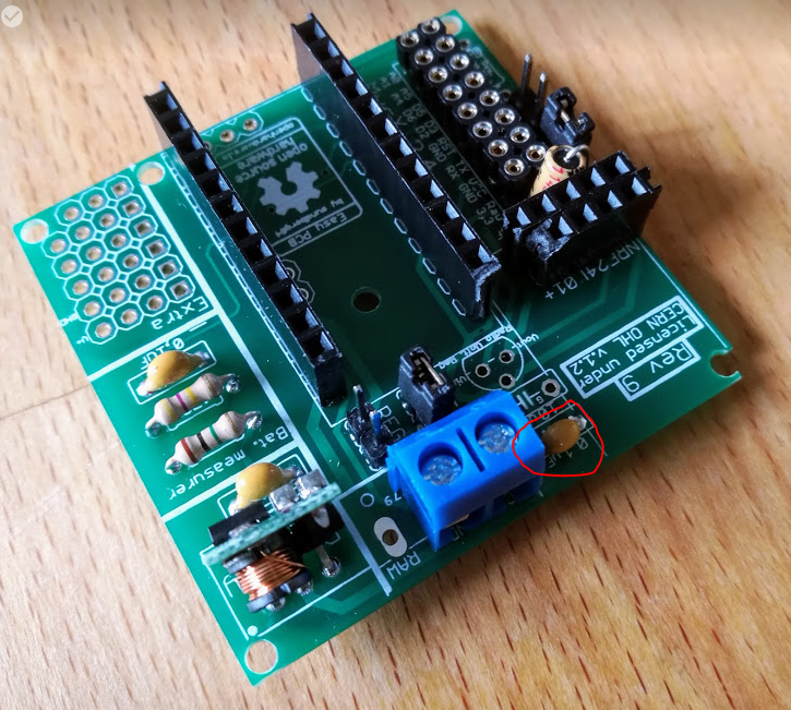
  • @jens-persson What's the 0.1 uF capacitor next to the battery terminals for?


  • Hardware Contributor

    @maghac - below the booster on the right side? it is an output capacitor to filter the output on the booster. There isnt any evidence this works and there are capacitors on the booster itself as well, but I found that a 0.1uF capacitor worked great on one of my nodes which was all ST=FAIL (radio transmit/ack fail) until i added this. I have found that a cheramic capacitors on the booster worked best for some reason.


  • @sundberg84 Aha, good to know. Can't hurt to add it I suppose.

    But I was actually wondering about the other one - to the left and above where the 5V->3.3V regulator would sit.


  • Hardware Contributor

    @maghac - this one?
    0_1494833219211_1.jpg

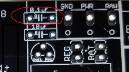
    Its to maintain stability of the voltage regulator. If you look at different datasheet most voltage regulators has a typical application schematics where different capacitors is added before and after to make this. So the 10 and 0,1uF work together. Why 0,1 and 10? Well - I have seen this setup on the forum many times so I just went with that. There is alof to read about this, but I think the smaller cap can react faster while the bigger cap have more juice to give so to say.

    https://electronics.stackexchange.com/questions/21686/whats-the-purpose-of-two-capacitors-in-parallel


  • @sundberg84 Ok, I see. I do have those caps on my (so far) only 5V mysensor node, somewhere I read that you need them but I wasn't sure why - thanks for the explanation.

    But I suppose there is no reason to add them unless you are actually using the voltage regulator to power the radio? I noticed that @jens-persson added the smaller cap on the pics he posted earlier, but those nodes were battery powered.

    0_1494834092470_Capture.PNG


  • Hardware Contributor

    @maghac - not really, I have not used them with batteries.
    In that setup the 0,1cap is in paralell with the 4,7uF cap for the radio. Sure, might give some more stability to the radio itself but the 4,7uF cap should be enought. If you experience alof of errors you can try adding different values here to give more stability - but in normal operations it should not be needed.

    Edit - sorry not 0,1uF, but 10uF cap is in parallell. The 0,1uF does nothing if you dont have a voltage regulator.

    Edit 2 (note to myself) - Maybe I should change the 0,1 and 10uF for next rev so 10 is on the input and 0,1uf on th output instead.


  • @sundberg84 Ok, it doesn't hurt since capacitors in parallel are simply just added (if I remember my electronics classes correctly).

    So the end result is that you have a 14.7 uF cap on the radio.


  • Hero Member

    @maghac it is not just as simple as the capacitor size is added, true it is added but different size capacitors also filter disturbances at different frequencies. So adding different size capacitors in parallel can act as a more effective disturbance filter.


  • Hardware Contributor

    @korttoma @maghac - Exactly how they work is beyond my knowledge... im more of a trial and error guy (hence the 9th revision ๐Ÿ™‚ ) but korttoma has right, and from experience I would go with a lower and a higher capacitor to try first, ie 0,1 and 10. 4,7 + 10 is to me two higher value capacitor.


  • A capacitor is considered a short to an AC signal and it works on certain frequencies depending on the setup. So if you get any AC ripple on your output of your regulator, the capacitor is used to smooth that out. Electrolytics are also use to give a quick extra burst of power when needed. That is why they are used for things like the incoming power for the radio. The radio transmits every so often and if you were to look at the power coming in to the radio on a scope with no capacitor on it, you would probably see dips in the power when it transmits. The dips in power could cause it to fall outside the operating range of the radio for a split second giving you transmission loss. The electrolytic is there to supply that extra jolt to stabilize the power on the transmit cycles.

    And @maghac, you are correct, parallel capacitance adds and series capacitance divides, which is the opposite of resistors where series resistance adds and parallel resistance divides.


  • Hardware Contributor

    @nitroburn said in ๐Ÿ’ฌ Easy/Newbie PCB for MySensors:

    @Nca78: Yeah, PCBways base price is $5 for 10 100x100 as well but they don't seem to charge for vcut (doesn't change quote) and allow 0mm spacing so no need to cut. I used EMS to ship and was here in 3 days without taxes or fees unlike DHL has every single time I use them. $15 just to collect $0.10 in tax.

    So yesterday I tried to submit my PCBs to PCBWay, they accept similar design if you don't check panelizing options, but my interest is to lower prices by combining different PCBs on the same board. I don't need them to cut anything, but they just refused and changed to panelized version. In the end it was 137$ compared to less than 70 with Seeed.
    So PCBWay is great to have many similar boards (but who really needs 50-60 items of the same board ?) but if you want to save costs by combining multiple boards it's not an option.


  • Hardware Contributor

    @Nca78 - This is exactly why i was shocked when someone got away with it. They get personally checked every time and soon as they pick something up where they can see two separate boards there then they refuse it unless you paid the extra for the panelising.


  • Mod

    Draw some fake routes across the boards, maybe they will not notice it ๐Ÿ˜€


  • @Nca78

    @Nca78 said in ๐Ÿ’ฌ Easy/Newbie PCB for MySensors:

    So yesterday I tried to submit my PCBs to PCBWay, they accept similar design if you don't check panelizing options, but my interest is to lower prices by combining different PCBs on the same board. I don't need them to cut anything, but they just refused and changed to panelized version. In the end it was 137$ compared to less than 70 with Seeed.
    So PCBWay is great to have many similar boards (but who really needs 50-60 items of the same board ?) but if you want to save costs by combining multiple boards it's not an option.

    I combined different PCBs and right on the form for submitting them for a quote it explains you just select how many different designs you want per board, so if you fit 3 different designs but with 8 total boards from the 100x100, you just enter 3 designs and submit all 3 gerbers individually zipped inside a main zip file. In my case, I selected 2 designs and submitted both as single not panalized. You can always just copypaste them together in eagle or something and avoid them saying anything about it.

    Only extra thing I did was submit the board size as the 2 designs added together then in the requirements specified there were 2 designs one being X * Y and the other X * Y. I don't know if they would have accepted me requesting they then put the designs onto one board more then once, but I assume that is what they would do for the panalization. It definitely doesn't have to be the same design on 1 board. Order 10 pcs, fit 4 designs or 2 designs 2 time and end up with 40 total PCBs. But I do notice if you have 2 designs done 8 times total and you want the boards pre-separated then you would say 8. But yeah, that does raise the price. Weird because I swear it wasn't doing it like that before.

    I guess I just got lucky and had a nice person review my files and they combined and separated them for me for free. In the future I'm just going to throw a panel together myself and submit as 1 design and maybe not even bother to have them score the boards, I'll do it myself and then it's definitely 1 design. They must have felt bad I was ordering 30x23 boards wasting the rest of the 100x100 so they threw them together. Its a 10 second copy and paste so I'll just do it myself next time and not bother with them charging more. Could also be they counted it as 1 design because the sizes were nearly identical.


  • A completely unrelated question: what is that header called that @jens-persson used on the MySX connector (see the pic that I reposted above)? I soldered the longer, jumper-style, headers instead so I can connect dupont wires.

    Are there any benefits to using this other type of header? (And what does the corresponding male connector look like)?


  • Hardware Contributor

    @maghac said in ๐Ÿ’ฌ Easy/Newbie PCB for MySensors:

    A completely unrelated question: what is that header called that @jens-persson used on the MySX connector (see the pic that I reposted above)? I soldered the longer, jumper-style, headers instead so I can connect dupont wires.

    Are there any benefits to using this other type of header? (And what does the corresponding male connector look like)?

    It's just header with round pins. No interest in using them IMHO, better stick to the standard square shaped headers as they are the more common. You cannot use standard square shaped headers with those so it's a bit limiting.


  • Please note, that when using the link to ITEAD, the order is not actually completed. The order is received by ITEAD, you get an order confirmation and everything, but the order is actually not processing before you upload the gerber files.

    This may be a beginners mistake, as it is the first time i'm using this service. I had the understanding that when you pressed the shopping cart above, and chose a service the gerber-part of the transaction would be handled automatic.

    I dont know if this is a misunderstanding on my side, I may have misunderstood the instructions on this site. It also may be an error on ITEAD's side as they didn't process the order correctly.
    What is your experience with this ?
    My problem is solved now, as I wrote and asked ITEAD for status. They made me aware of the issue and I emailed them the gerbers.

    This is in no way a critique of the project. I really appreciate the hours of work put into it.


  • Admin

    @R2DK, sounds strange.

    Should just be a one-click operation to order... and you shouldn't have to do any gerber uploads.
    Could you PM me who you were in contact with over at ITEAD?


  • Hardware Contributor

    We have sold pcbs from itead before and this is the first time I hear this. As @hek said it should be a 1 click operation but something maybe went wrong just this time?


  • This happened to me too, I ordered from the link, and thought I was Ok with the order. Yesterday I did find out that my order was waiting for the gerber files, so I downloaded, zipped and uploaded the to itead. I also mailed them about it. Got a reply that they should check the gerber files.


  • Hardware Contributor

    @mickecarlsson - I think @hek are looking into this... if I look at my Sales stat there are mostly ordered/aborted from Itead without known reason so they have not been comfirmed. The lastest revision from EasyPCB is over 7 months old and works great with PCBway... so if the gerber files are bad I hope I would have been notised before.


  • Admin

    I have mailed the person responsible for the integration. Hope to get some answers tomorrow.


  • Allright, now it looks like I am getting them ๐Ÿ‘
    PCBs have been finished and are ready to be sent out.


  • same hear...i ordered from itead...i had to upload the gerbers myself....


  • I have some issues with battery powered version with this board, maybe someone can point out what I did wrong. I have several of these boards working great (rev 8 says on them, the radio cap is however properly connected). I recently noticed that battery powered sensors do not work if battery is under 2.7v (on one pro mini it goes under 2.3v) even thought I have 3.3v booster. I have one dht22 sensor, measuring resistors and cap, bat jumper, basically my board looks exactly like example on the openharware, this one https://www.openhardware.io//uploads/568ed84b60aa3f8965fbf095/image/Rev8 Bat.jpg
    Also did the battery hack, removed led and removed onboard regulator.
    I have rechecked several times, changed several radios and several arduinos, but they just wont work reliably on lover battery power then 2.8v . Is that the limit?
    I cannot debug using serial adapter, as when I connect it, then pro works fine as it gets 3.3v from the pc.
    But here is some debug measurements I did on 2.5v batteries: vcc - gnd pins on pro mini show 3.3v. Pins out of booster do show 3.3v. So do pins on the dht22.
    Pins on the radio show 2.5v, so do D2-gnd show 2.5v (or -2.5v i forgot). Why does pin2 have 2.5v, I have desoldered it so it is not connected to anything, I guess that is some feedback voltage from the radio (as dht22 gets 3.3v) Can this pin (or voltage measurement a0) somehow disturb the pro mini?
    Do you have some suggestions on how I can debug what is going on?
    The led on arduino goes red for 3-4s, then goes off for 2s then again red for 3s, then off...
    I have two identical boards, and only thing that is determining the lov limit is pro mini modules. Some of them go to 2.7v (on both boards) and on of them goes down to 2.3v on both boards. I do not understand why when they do get 3.3v on the vcc from the booster?

    What is the lowest voltage the batteries can go (with the 3.3v booster)?


  • Hardware Contributor

    @dakipro - hi!

    but they just wont work reliably on lover battery power then 2.8v . Is that the limit?

    No, the limit should be (if you have a genuine radio) 1,9v. Im not sure what kind of voltages a clone will manage, but my nodes goes below 2.8v!

    I cannot debug using serial adapter, as when I connect it, then pro works fine as it gets 3.3v from the pc.

    This should not be a problem - you can power the node from the "normal" way and just connect RX/TX and GND from the ftdi to the arduino ftdi header. I have done this several times.

    D2-gnd show 2.5v

    The IRQ line from the radio is 2.5v since thats what the radio gets. Im not exactly sure what this does, but in SPI which is what the radio are using, its either HIGH or LOW so 2.5v sounds right since the radio has that voltage. This should not disturb the arduino! This is changed in REV9 so you can disconnect D2 from the radio if wanted. You should not use D2 for any sensor below Rev9.

    The led on arduino goes red for 3-4s, then goes off for 2s then again red for 3s, then off...

    Sounds like the radio is transmitting... if this goes on and on it can mean the radio isnt getting connected/ack or establish a way to the gateway.

    Do you have some suggestions on how I can debug what is going on?

    You need to check the debut output (see above)!
    Could you describe the issue? Are the node lost from the controller?

    What is the lowest voltage the batteries can go (with the 3.3v booster)?

    1.9v is the minimum to the radio.
    0,8v is the minimum for the booster.


  • Thank you for your answer, the tip about debugging helped a lot.
    I now checked on one board and it looks that some pro minis are having problems when battery voltage goes bellow certain level (f.eks. 2.7v).
    Testing results:
    "good pro mini" works up to 2.0v , on 1.9v it shows fallowing errors

    send: 4-4-0-0 s=1,c=0,t=7,pt=0,l=0,sg=0,st=fail:
    find parent
    send: 4-4-255-255 s=255,c=3,t=7,pt=0,l=0,sg=0,st=bc:
    send: 4-4-0-0 s=2,c=0,t=6,pt=0,l=0,sg=0,st=fail:
    temp: nan
    nan
    send: 4-4-0-0 s=255,c=3,t=0,pt=1,l=1,sg=0,st=fail:62
    send: 4-4-0-0 s=2,c=1,t=0,pt=7,l=5,sg=0,st=fail:0.00
    send: 4-4-0-0 s=1,c=1,t=1,pt=7,l=5,sg=0,st=fail:0.0
    

    "bad pro mini" works fine above 2.7, on 2.6 it logs

    
    84973 MCO:SLP:MS=15000,SMS=1,I1=255,M1=255,I2=255,M2=255
    85047 !MCO:SLP:TNR
    85874 TSM:FAIL:RE-INIT
    85897 TSM:INIT
    85919 TSM:INIT:TSP OK
    85942 TSM:INIT:STATID=3
    85968 TSF:SID:OK,ID=3
    85991 TSM:FPAR
    86042 TSF:MSG:SEND,3-3-255-255,s=255,c=3,t=7,pt=0,l=0,sg=0,ft=0,st=OK:
    88117 !TSM:FPAR:NO REPLY
    88141 TSM:FPAR
    88193 TSF:MSG:SEND,3-3-255-255,s=255,c=3,t=7,pt=0,l=0,sg=0,ft=0,st=OK:
    90269 !TSM:FPAR:NO REPLY
    90294 TSM:FPAR
    90345 TSF:MSG:SEND,3-3-255-255,s=255,c=3,t=7,pt=0,l=0,sg=0,ft=0,st=OK:
    92422 !TSM:FPAR:NO REPLY
    92446 TSM:FPAR
    92497 TSF:MSG:SEND,3-3-255-255,s=255,c=3,t=7,pt=0,l=0,sg=0,ft=0,st=OK:
    94574 !TSM:FPAR:FAIL
    94595 TSM:FAIL:CNT=4
    94617 TSM:FAIL:PDT
    95066 MCO:SLP:MS=4999
    95088 !TSF:SND:TNR
    95610 MCO:SLP:TPD


    What I see on the log parser is that the "No potential parents replied to find parent request" pops out as the biggest issue, suggesting that radio communication is not doing well.

    I am testing using the small bench power supply (the Chinese ones with the oled screen) so the current should not be the problem. Why would pro mini be the problem, when it is getting 3.3v directly from same stepup?
    The radio and all other components are exactly the same in all the tests i just swap the minis, I think radio would have failed with both minis if it is the radio... or perhaps the signal to the radio is not good/stable enough? No idea to be honest ๐Ÿ™‚

    If that matters: they are all getting 2.7v (or what I set) on pin 2 even though I have physically cut the connection to the radio irq (with the knife, on the board, they are not touching anything else on the board).

    p.s. now that I write this, i realize that another difference is the sketch on them, "the good one" is "vanilla" mysensors 1.5 code and all the bad ones are latest mysensors using the node-manager library. I do not know enough about chip programming, but as a web developer I would think that the code should not determine minimum voltage needed on board? (or there are some routines in some strange combination doing some magic... hm...)


  • Well I just tested with latest example from mysensors library, and we can exclude my latest p.s., nothing to do with using the node-manager (as expected).
    Only difference is the pro minis (but again, they should all get 3.3v via popup)?
    and on the "good" node I have mysensors 1.5 while on the others I use 2.1.


  • Hardware Contributor

    @dakipro - It looks like when the voltage drops, you are having issues with your radio (No reply and ST=Fail).
    This should not be a problem, since this is powered directly from the batteries and you say there are 2.8v left.

    The first thing that comes to my mind is that as the voltage drops, the booster needs to work harder and introduces more noice into the board. As the noice increase, the radio gets in trouble.
    The other I can imagine is that you have a bad clone which cant handle lower voltages.

    Both problems are a bit tricky to diagnose. First I would try some different radios, if possible from different batches. Second I would look more close to the booster. They vary greatly in quality and some are just really bad. Sometimes a cheramic capacitor might help (from output to gnd on the booster). You could also just disconnect the booster and see if it works (the pro mini shoudl be able to handle down to 2.8v).


  • After several hours of debugging and changing all possible components, i built exactly same circuit on prototype board and with exactly same (active) components I was able to go down to 1.9, sometimes to 1.8, while on the easyboard only down to 2.6. I also used exactly the same booster on both prototype and on the easyboard.

    But then a breakthrough, I have found one passive component that was different between the two mentioned boards! It was the radio freaking capacitor, on the "good" board it was 47uf, and on the problematic board had 4.7uf!
    I changed radio cap to 47uf and I am now able to go on both boards down to 2.3v. Which is ok, not the 1.9v but it is good enough (for now ๐Ÿ™‚ ) So those 42.3uf were missing for radio to go ~0.5v lower in voltage I guess.

    The one thing I am missing on the prototyping board is the voltage measurement circuit, so I guess that gives some 0.4v lowest threshold or something, i will test these days on the prototyping board, just to verify.

    Thank you @sundberg84 for attention and help ๐Ÿ™‚

    Are you able to provide 1.9v on battery input on some easy board with the dht22? Like the one from the photos on the openhardware?


  • Hardware Contributor

    @dakipro - the radio capacitor is crusial which has been proven many times before so good you found out your problem. What can be a pain with the radios is that some clones/batches seems to work with on capacitor value and the next need some higher/lower value on the capacitor to work at its best.

    The source is most likley what i explained above, the booster noice which interfere with the radio. On a breadboard you have much more space and possibility to put the booster further away from the radio with longer wires. This is most likley your case here...

    Are you able to provide 1.9v on battery input on some easy board with the dht22? Like the one from the photos on the openhardware?

    I have not made any a large quantity of measurments, because i almost never have to change my AA batteries. I have 5 Easy nodes (different revs though) with DHT22 and the only time I measured it was around 2 if I remember right. Cant remember if it was 2.0 or 2.2 though... I will keep that in mind for the next battery change but the lowest node is at 2.5V at the moment so it might take a while. If I remember right according to Domoticz I will not have to change these batteries for atleast a couple of months.

    So the short answer... im not far from 1.9V, but It will depend on the radio and the booster quality.


  • @dakipro Jut to test, now that you have your voltages closer with the change in capacitor, you may want to just try swapping the radio modules between the two (provided you have them in sockets) and see if the voltage drop follows the radio.
    .


  • both boards are now identical, they go down to 2.3, but I will put 2.4 in scripts as the minimum, just to be sure.
    If a board boots at 2.4 it can go down til 2.2 and maybe 2.1, and it will work, but cannot reboot at that voltage.


  • Hardware Contributor

    @dakipro - 2.4 volts will last you a long time.

    If you want to go further I would suggest you look at the advanced user section of the EasyPCB and remove the booster and lower BOD instead. This will not work with the DHT22 but you could change that to BME280 and the radio @ 1.9v will be your lowest point. Either that or go for a more expensive booster. Im accually trying this in another project (https://www.sparkfun.com/products/10967) so I can give some feedback in a near future.

    Im also building a variable power supply which might help me to try different volt levels on my boards as well... all I need now is a oscilloscope - anyone wants to fund (and teach) me ๐Ÿ™‚ ?


  • I will consider that for new nodes. Where is a "advanced user section of the EasyPCB", i tried searching the forum and openhardware, but not sure what exactly you are referring to?


  • Mod

    @sundberg84 wow, that's a quite expensive booster ๐Ÿ˜ฐ


  • Hardware Contributor

    @gohan - yes almost 5 times more expensive but I'm building it myself and it's probably five times better...

    @dakipro https://www.openhardware.io/view/4/EasyNewbie-PCB-for-MySensors check "Battery without step up booster (advanced users)"


  • Hardware Contributor

    @gohan said in ๐Ÿ’ฌ Easy/Newbie PCB for MySensors:

    @sundberg84 wow, that's a quite expensive booster ๐Ÿ˜ฐ

    The chip itself is less than 0.7$ on Arrow.com (so, legit one) so with additional components it should be 2$.

    But I see in the datasheet that typical operating current for 3.3V version is 45uA, added to the 15% of losses (max 85% efficiency) I'm a bit skeptical about the battery life you can get using it ?

    @sundberg84 if you find someone funding oscilloscopes, please send me the contact ๐Ÿ˜„ Else you have the captures in the datasheet for the most critical cases ๐Ÿ˜›


  • Hardware Contributor

    @Nca78 45 uA will last me a long time. On my dht nodes I aim for <100uA so if you sleep between readings that's ok. If this circuit would be much better than these cheap eBay boosters I'm happy even if they run at a couple of more uA

    Will let you know if I find oscilloscope funder ๐Ÿ˜‰


  • Hardware Contributor

    @sundberg84 said in ๐Ÿ’ฌ Easy/Newbie PCB for MySensors:

    @Nca78 45 uA will last me a long time. On my dht nodes I aim for <100uA so if you sleep between readings that's ok. If this circuit would be much better than these cheap eBay boosters I'm happy even if they run at a couple of more uA

    Will let you know if I find oscilloscope funder ๐Ÿ˜‰

    But I still fail to see the interest of all the pain with the boosters and keeping the DHT22 which need "high" voltage of 3.3V when a sht21/si7021 is 3$ or less on aliexpress and can run way over 1 year with a simple cr2032 ? And if you use 2 AA it will run for 5 years. No problem with noise/stability, no booster to buy, just a 0.x$ big capacitor to add in parallel with the battery if you're using a CR2032 (and nothing if you're using 2 AA/AAA).


  • @Nca78 Another option that I went with is an HDC1080. The only problem with this one is that according to the datasheet, the recommended operating minimum voltage is 2.7v, where the si7021's minimum is 1.9v. When I was looking on ebay, these said that they were a replacement for the si7021, and it was my mistake not checking the datasheet before buying. They do seem to be working good though and I have had one of them running for about 5 months with no trouble so far.


  • Hardware Contributor

    @Nca78 that's why I added the option without boosters. The only downside is that it's not that easy changing bod. When you get the booster function to work you can also run a motion dec in 3.3v for example. 3.3v will give you more sensor options.


  • @sundberg84 said in ๐Ÿ’ฌ Easy/Newbie PCB for MySensors:

    Battery without step up booster (advanced users)

    I could just (do it very very ugly) and cut the vcc line near the board and solder it directly to the battery input?
    That way both arduino and radio will get battery power, and dht22 would still receive 3.3v? (then I can lower the BOD)
    Or would that not work due to some other connection?

    Also, would flashing pro mini to 1Mhz benefit battery consumption at all? (while still using 3.3 booster)

    (p.s. I stole your signature ๐Ÿ™‚ )


  • @sundberg84 That is one of the nice things about your board is it's flexibility.


  • Hardware Contributor

    @sundberg84 said in ๐Ÿ’ฌ Easy/Newbie PCB for MySensors:

    @Nca78 that's why I added the option without boosters. The only downside is that it's not that easy changing bod. When you get the booster function to work you can also run a motion dec in 3.3v for example. 3.3v will give you more sensor options.

    Well, it is pretty easy IMHO, you just have to follow on of the many tutorials, and you learn a lot on the way ๐Ÿ™‚
    For motion detection isn't a booster a bad idea ? You can use AM312 anyway, very small and very stable, no soldering necessary to run it down to 2.7V meaning you can use most of the capacity of a lithum cell like CR123.

    @dbemowsk thanks for the information I didn't even know about this sensor, looks like a very precise one with a very low power consumption. Can you link to where you bought it from I see nothing below 4$ on aliexpress ?


  • @Nca78 said in ๐Ÿ’ฌ Easy/Newbie PCB for MySensors:

    when a sht21/si7021 is 3$ or less on aliexpress

    The thing is that when people start with mysensors and arduinos, none of these are listed on Store page, so using them would be experimenting basically. And experimenting before you have even begun anything is a bit masochistic. At least in my case that is how I was thinking, so I ordered several of dht22, not really knowing that there are better/efficient alternatives. Maybe we can get those sensors in the store page, perhaps mention them on the examples page, noting that they are more efficient?


  • I went for the BME280, a little expensive, but it uses I2C and can be run from 1.71 volt to 3.3 volt.


  • @Nca78 I believe this is the same one that I bought, at least the carrier board looks to be labeled the same. Mine was just listed as an HDC1080, where this one is listed as a GY-213V-HDC1080. I am assuming it is the same chip. When I bought the 2 that I have I paid $5/module shipped which after looking at this one was a bit high. Live and learn though.

    http://www.ebay.com/itm/Low-Power-GY-213V-HDC1080-I2C-High-Accuracy-Digital-Humidity-Temperature-Sensor-/172666252980?hash=item2833b5eeb4:g:1C8AAOSwi7RZELpK


  • Hardware Contributor

    @dakipro the dht22 is a hot potato not only due to 3.3 req but also quality... I know this has been requested for removal on homepage before and I think it's just a matter of someone makes a good example for another sensor to replace it with.

    Yes you can cut the trace for vcc and hardwire it from bat if you want to lower bod.

    And yes it's not that hard to lower bod... but harder than booster and therefore I choose the easiest option since that's my board goal.

    I'm running 1mhz with booster and motion without problems... but same there, with a bad booster it will false trigger.


  • Mod

    This might be the better example you are looking for https://github.com/mysensors/MySensorsArduinoExamples/pull/25


Suggested Topics

  • 5
  • 11
  • 13
  • 13
  • 5
  • 39
  • 8
  • 1

19
Online

11.2k
Users

11.1k
Topics

112.5k
Posts