💬 Easy/Newbie PCB for MySensors
-
I never received so fast with EMS.
And I'm always dubious about the ultra positive comments on PCBWay as you never know (in fact, you know it :P ) if it's a way to get a discount for the next order via their marketing program....
I never did it because my experience with them is mixed, they have a fancy website with all process details but the PCB they sent me had really subpar silkscreen, way lower quality than any other PCB makers. And on one of my boards (not EasyPCB which was ok) I had problem with quality with a long track that peeled away when I unsoldered a component to replace it. Never had that on boards from DirtyPCB or Seeed.
@Nca78 and I've had a bunch of problems with seeed, however that wasn't related to their pcb services just their store and various bugs with the site that I had to multiple times point out to them and months later still needed to be fixed. (ie, incorrect paypal checkout flow that processes orders without a chance for final review as it should, and says will happen. Other people's PCB orders filling my cart with their gerbers and all. selling a galileo gen2 board right beside a gen1 case with no mention of incompatibility or that the case was for gen1 and at the time only the gen2 and that one case was for sale and they didn't seem to care that it was confusing, plus many other issues across just a couple orders. Seemed to be horrible customer service there.)
-
So it is cheaper to combine different boards and have them cut into single boards instead of ordering them on separate orders?
Everytime I panelize anything I get charged for specifying that it is panelized, even if i specify that i've done it and don't need them to do such. Do you just submit the board as a normal board but have your milling and drills such that it allows you to remove them all when you receive the product?
-
Everytime I panelize anything I get charged for specifying that it is panelized, even if i specify that i've done it and don't need them to do such. Do you just submit the board as a normal board but have your milling and drills such that it allows you to remove them all when you receive the product?
@Samuel235 you should not specify that you have panelized your boards.
And yes I use milling for complex shapes so I just have a few straight lines to cut with scissors. I did it with DirtyPCB last time and had no problem.
Seeed explains you should just not select panelizing related options when you order and they will not care. -
:-(
Thought the settings on the album should apply to the images also.
Here is a link to the album: https://goo.gl/photos/bX9HZSXdbMCvuyAv9
Does it work?@jens-persson What's the 0.1 uF capacitor next to the battery terminals for?
-
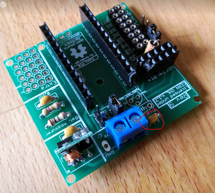
@jens-persson What's the 0.1 uF capacitor next to the battery terminals for?
@maghac - below the booster on the right side? it is an output capacitor to filter the output on the booster. There isnt any evidence this works and there are capacitors on the booster itself as well, but I found that a 0.1uF capacitor worked great on one of my nodes which was all ST=FAIL (radio transmit/ack fail) until i added this. I have found that a cheramic capacitors on the booster worked best for some reason.
Controller: Proxmox VM - Home Assistant
MySensors GW: Arduino Uno - W5100 Ethernet, Gw Shield Nrf24l01+ 2,4Ghz
MySensors GW: Arduino Uno - Gw Shield RFM69, 433mhz
RFLink GW - Arduino Mega + RFLink Shield, 433mhz -
@maghac - below the booster on the right side? it is an output capacitor to filter the output on the booster. There isnt any evidence this works and there are capacitors on the booster itself as well, but I found that a 0.1uF capacitor worked great on one of my nodes which was all ST=FAIL (radio transmit/ack fail) until i added this. I have found that a cheramic capacitors on the booster worked best for some reason.
@sundberg84 Aha, good to know. Can't hurt to add it I suppose.
But I was actually wondering about the other one - to the left and above where the 5V->3.3V regulator would sit.
-
@sundberg84 Aha, good to know. Can't hurt to add it I suppose.
But I was actually wondering about the other one - to the left and above where the 5V->3.3V regulator would sit.
@maghac - this one?
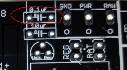
Its to maintain stability of the voltage regulator. If you look at different datasheet most voltage regulators has a typical application schematics where different capacitors is added before and after to make this. So the 10 and 0,1uF work together. Why 0,1 and 10? Well - I have seen this setup on the forum many times so I just went with that. There is alof to read about this, but I think the smaller cap can react faster while the bigger cap have more juice to give so to say.
Controller: Proxmox VM - Home Assistant
MySensors GW: Arduino Uno - W5100 Ethernet, Gw Shield Nrf24l01+ 2,4Ghz
MySensors GW: Arduino Uno - Gw Shield RFM69, 433mhz
RFLink GW - Arduino Mega + RFLink Shield, 433mhz -
@maghac - this one?
Its to maintain stability of the voltage regulator. If you look at different datasheet most voltage regulators has a typical application schematics where different capacitors is added before and after to make this. So the 10 and 0,1uF work together. Why 0,1 and 10? Well - I have seen this setup on the forum many times so I just went with that. There is alof to read about this, but I think the smaller cap can react faster while the bigger cap have more juice to give so to say.
@sundberg84 Ok, I see. I do have those caps on my (so far) only 5V mysensor node, somewhere I read that you need them but I wasn't sure why - thanks for the explanation.
But I suppose there is no reason to add them unless you are actually using the voltage regulator to power the radio? I noticed that @jens-persson added the smaller cap on the pics he posted earlier, but those nodes were battery powered.
-
@sundberg84 Ok, I see. I do have those caps on my (so far) only 5V mysensor node, somewhere I read that you need them but I wasn't sure why - thanks for the explanation.
But I suppose there is no reason to add them unless you are actually using the voltage regulator to power the radio? I noticed that @jens-persson added the smaller cap on the pics he posted earlier, but those nodes were battery powered.
@maghac - not really, I have not used them with batteries.
In that setup the 0,1cap is in paralell with the 4,7uF cap for the radio. Sure, might give some more stability to the radio itself but the 4,7uF cap should be enought. If you experience alof of errors you can try adding different values here to give more stability - but in normal operations it should not be needed.Edit - sorry not 0,1uF, but 10uF cap is in parallell. The 0,1uF does nothing if you dont have a voltage regulator.
Edit 2 (note to myself) - Maybe I should change the 0,1 and 10uF for next rev so 10 is on the input and 0,1uf on th output instead.
Controller: Proxmox VM - Home Assistant
MySensors GW: Arduino Uno - W5100 Ethernet, Gw Shield Nrf24l01+ 2,4Ghz
MySensors GW: Arduino Uno - Gw Shield RFM69, 433mhz
RFLink GW - Arduino Mega + RFLink Shield, 433mhz -
@maghac - not really, I have not used them with batteries.
In that setup the 0,1cap is in paralell with the 4,7uF cap for the radio. Sure, might give some more stability to the radio itself but the 4,7uF cap should be enought. If you experience alof of errors you can try adding different values here to give more stability - but in normal operations it should not be needed.Edit - sorry not 0,1uF, but 10uF cap is in parallell. The 0,1uF does nothing if you dont have a voltage regulator.
Edit 2 (note to myself) - Maybe I should change the 0,1 and 10uF for next rev so 10 is on the input and 0,1uf on th output instead.
@sundberg84 Ok, it doesn't hurt since capacitors in parallel are simply just added (if I remember my electronics classes correctly).
So the end result is that you have a 14.7 uF cap on the radio.
-
@sundberg84 Ok, it doesn't hurt since capacitors in parallel are simply just added (if I remember my electronics classes correctly).
So the end result is that you have a 14.7 uF cap on the radio.
@maghac it is not just as simple as the capacitor size is added, true it is added but different size capacitors also filter disturbances at different frequencies. So adding different size capacitors in parallel can act as a more effective disturbance filter.
-
@maghac it is not just as simple as the capacitor size is added, true it is added but different size capacitors also filter disturbances at different frequencies. So adding different size capacitors in parallel can act as a more effective disturbance filter.
-
A capacitor is considered a short to an AC signal and it works on certain frequencies depending on the setup. So if you get any AC ripple on your output of your regulator, the capacitor is used to smooth that out. Electrolytics are also use to give a quick extra burst of power when needed. That is why they are used for things like the incoming power for the radio. The radio transmits every so often and if you were to look at the power coming in to the radio on a scope with no capacitor on it, you would probably see dips in the power when it transmits. The dips in power could cause it to fall outside the operating range of the radio for a split second giving you transmission loss. The electrolytic is there to supply that extra jolt to stabilize the power on the transmit cycles.
And @maghac, you are correct, parallel capacitance adds and series capacitance divides, which is the opposite of resistors where series resistance adds and parallel resistance divides.
-
@sundberg84: sadly I only did it for the jModule boards but realize now I should have done it with your board as well since I could have got 4x as many for the same price. I realized after I could have got significantly more of those as well, or just have spent less. Might have had to trim a little bit from the dimensions though as I don't know about clearances using the full 100x100 without room to split the boards, but I could be wrong due to them being square Actually, after just checking pcbway's site it says, "Leave min clearance of 1.6mm between boards for break-routing. For V-score panelization, set the space between boards to be zero." so I could have got 120 boards for $25 as they are actually 48.66x49.86 per board. Or combined different boards together as I think 120 would be overkill :) I never realized how inexpensive it is compared to etching your own. It would be crazy to etch at these prices.
Thanks for the great starting point and learning experience.
@Nca78: Yeah, PCBways base price is $5 for 10 100x100 as well but they don't seem to charge for vcut (doesn't change quote) and allow 0mm spacing so no need to cut. I used EMS to ship and was here in 3 days without taxes or fees unlike DHL has every single time I use them. $15 just to collect $0.10 in tax.
@nitroburn said in 💬 Easy/Newbie PCB for MySensors:
@Nca78: Yeah, PCBways base price is $5 for 10 100x100 as well but they don't seem to charge for vcut (doesn't change quote) and allow 0mm spacing so no need to cut. I used EMS to ship and was here in 3 days without taxes or fees unlike DHL has every single time I use them. $15 just to collect $0.10 in tax.
So yesterday I tried to submit my PCBs to PCBWay, they accept similar design if you don't check panelizing options, but my interest is to lower prices by combining different PCBs on the same board. I don't need them to cut anything, but they just refused and changed to panelized version. In the end it was 137$ compared to less than 70 with Seeed.
So PCBWay is great to have many similar boards (but who really needs 50-60 items of the same board ?) but if you want to save costs by combining multiple boards it's not an option. -
@nitroburn said in 💬 Easy/Newbie PCB for MySensors:
@Nca78: Yeah, PCBways base price is $5 for 10 100x100 as well but they don't seem to charge for vcut (doesn't change quote) and allow 0mm spacing so no need to cut. I used EMS to ship and was here in 3 days without taxes or fees unlike DHL has every single time I use them. $15 just to collect $0.10 in tax.
So yesterday I tried to submit my PCBs to PCBWay, they accept similar design if you don't check panelizing options, but my interest is to lower prices by combining different PCBs on the same board. I don't need them to cut anything, but they just refused and changed to panelized version. In the end it was 137$ compared to less than 70 with Seeed.
So PCBWay is great to have many similar boards (but who really needs 50-60 items of the same board ?) but if you want to save costs by combining multiple boards it's not an option.@Nca78 - This is exactly why i was shocked when someone got away with it. They get personally checked every time and soon as they pick something up where they can see two separate boards there then they refuse it unless you paid the extra for the panelising.
-
@nitroburn said in 💬 Easy/Newbie PCB for MySensors:
@Nca78: Yeah, PCBways base price is $5 for 10 100x100 as well but they don't seem to charge for vcut (doesn't change quote) and allow 0mm spacing so no need to cut. I used EMS to ship and was here in 3 days without taxes or fees unlike DHL has every single time I use them. $15 just to collect $0.10 in tax.
So yesterday I tried to submit my PCBs to PCBWay, they accept similar design if you don't check panelizing options, but my interest is to lower prices by combining different PCBs on the same board. I don't need them to cut anything, but they just refused and changed to panelized version. In the end it was 137$ compared to less than 70 with Seeed.
So PCBWay is great to have many similar boards (but who really needs 50-60 items of the same board ?) but if you want to save costs by combining multiple boards it's not an option.@Nca78 said in 💬 Easy/Newbie PCB for MySensors:
So yesterday I tried to submit my PCBs to PCBWay, they accept similar design if you don't check panelizing options, but my interest is to lower prices by combining different PCBs on the same board. I don't need them to cut anything, but they just refused and changed to panelized version. In the end it was 137$ compared to less than 70 with Seeed.
So PCBWay is great to have many similar boards (but who really needs 50-60 items of the same board ?) but if you want to save costs by combining multiple boards it's not an option.I combined different PCBs and right on the form for submitting them for a quote it explains you just select how many different designs you want per board, so if you fit 3 different designs but with 8 total boards from the 100x100, you just enter 3 designs and submit all 3 gerbers individually zipped inside a main zip file. In my case, I selected 2 designs and submitted both as single not panalized. You can always just copypaste them together in eagle or something and avoid them saying anything about it.
Only extra thing I did was submit the board size as the 2 designs added together then in the requirements specified there were 2 designs one being X * Y and the other X * Y. I don't know if they would have accepted me requesting they then put the designs onto one board more then once, but I assume that is what they would do for the panalization. It definitely doesn't have to be the same design on 1 board. Order 10 pcs, fit 4 designs or 2 designs 2 time and end up with 40 total PCBs. But I do notice if you have 2 designs done 8 times total and you want the boards pre-separated then you would say 8. But yeah, that does raise the price. Weird because I swear it wasn't doing it like that before.
I guess I just got lucky and had a nice person review my files and they combined and separated them for me for free. In the future I'm just going to throw a panel together myself and submit as 1 design and maybe not even bother to have them score the boards, I'll do it myself and then it's definitely 1 design. They must have felt bad I was ordering 30x23 boards wasting the rest of the 100x100 so they threw them together. Its a 10 second copy and paste so I'll just do it myself next time and not bother with them charging more. Could also be they counted it as 1 design because the sizes were nearly identical.
-
A completely unrelated question: what is that header called that @jens-persson used on the MySX connector (see the pic that I reposted above)? I soldered the longer, jumper-style, headers instead so I can connect dupont wires.
Are there any benefits to using this other type of header? (And what does the corresponding male connector look like)?
@maghac said in 💬 Easy/Newbie PCB for MySensors:
A completely unrelated question: what is that header called that @jens-persson used on the MySX connector (see the pic that I reposted above)? I soldered the longer, jumper-style, headers instead so I can connect dupont wires.
Are there any benefits to using this other type of header? (And what does the corresponding male connector look like)?
It's just header with round pins. No interest in using them IMHO, better stick to the standard square shaped headers as they are the more common. You cannot use standard square shaped headers with those so it's a bit limiting.
-
Please note, that when using the link to ITEAD, the order is not actually completed. The order is received by ITEAD, you get an order confirmation and everything, but the order is actually not processing before you upload the gerber files.
This may be a beginners mistake, as it is the first time i'm using this service. I had the understanding that when you pressed the shopping cart above, and chose a service the gerber-part of the transaction would be handled automatic.
I dont know if this is a misunderstanding on my side, I may have misunderstood the instructions on this site. It also may be an error on ITEAD's side as they didn't process the order correctly.
What is your experience with this ?
My problem is solved now, as I wrote and asked ITEAD for status. They made me aware of the issue and I emailed them the gerbers.This is in no way a critique of the project. I really appreciate the hours of work put into it.
Hello! It looks like you're interested in this conversation, but you don't have an account yet.
Getting fed up of having to scroll through the same posts each visit? When you register for an account, you'll always come back to exactly where you were before, and choose to be notified of new replies (either via email, or push notification). You'll also be able to save bookmarks and upvote posts to show your appreciation to other community members.
With your input, this post could be even better 💗
Register Login