💬 Easy/Newbie PCB for MySensors
-
Looks nice in red ;)
-
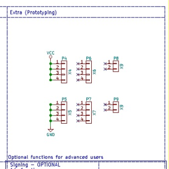
hello, i have a stupid question... on the 3 rows below VCC and GD on your prototyping area; are the rows connected horizontally like a breadboard? thanks
-
hello, i have a stupid question... on the 3 rows below VCC and GD on your prototyping area; are the rows connected horizontally like a breadboard? thanks
@pierre1410 - no stupid questions, simple answer though, no :)
-
Hello Sundberg84 et al,
I purchased Easy Newbie PCB (Rev 10) with the hope of jumping into the IoT rave... I tried to create the Gateway - and it works perfectly. I also found and created an advanced Water Sprinkler MyS project by Pete and Co!... that also worked perfectly.However, I cant seem to get simpler beginner sketches to work with EasyNewbie. I have soldered the need components (the regulated version). I plan to connect to a 4 relay module, but for now, I am simulating the relay with a simple LED attached to D2. I have uploaded the following sketch which was originally written for version 1.0 MySensors - but have been corrected using guidelines I found for converting 1.0 - 2.0 version. but still no cheese - the controller (Domoticz) displays the Node, but not the complete child nodes, - the LED connected to pin D2 (or D3, D5..) on the Easy Newbie doesn't light up even when I toggle the switches and devices on controller. Don't know what I might be doing wrong, please help.
// Example sketch showing how to control physical relays. // This example will remember relay state even after power failure. // Enable debug prints #define MY_DEBUG // Enable and select radio type attached #define MY_RADIO_NRF24 #define MY_NODE_ID 4 // Set this to fix your Radio ID or use AUTO or 1 #define MY_REGISTRATION_FEATURE // Forece registration #define MY_REGISTRATION_RETRIES 5 #include <Wire.h> #include <TimeLib.h> #include <SPI.h> #include <MySensors.h> #include <LCD.h> #include <LiquidCrystal.h> #include <LiquidCrystal_I2C.h> // For Debug #ifdef DEBUG_ON #define DEBUG_PRINT(x) Serial.print(x) #define DEBUG_PRINTLN(x) Serial.println(x) #else #define DEBUG_PRINT(x) #define DEBUG_PRINTLN(x) #define SERIAL_START(x) #endif //#define RELAY_1 2 // Arduino Digital I/O pin number for first relay (second on pin+1 etc) #define RELAY_PIN 3 #define NUMBER_OF_RELAYS 4 // Total number of attached relays #define RELAY_ON 0 // GPIO value to write to turn on attached relay #define RELAY_OFF 1 // GPIO value to write to turn off attached relay #define SKETCH_NAME "Base Relay Node" #define SKETCH_VERSION "0.1.2" #define CHILD_ID 0 MyMessage msg(1,V_LIGHT); //void before() void setup() { for (int sensor=1, pin=RELAY_PIN; sensor<=NUMBER_OF_RELAYS; sensor++, pin++) { // Then set relay pins in output mode pinMode(pin, OUTPUT); // Set relay to last known state (using eeprom storage) digitalWrite(pin, loadState(sensor)?RELAY_ON:RELAY_OFF); } } void presentation() { sendSketchInfo(SKETCH_NAME, SKETCH_VERSION); // Fetch relay status for (int sensor=1, pin=RELAY_PIN; sensor<=NUMBER_OF_RELAYS; sensor++, pin++) { // Register all sensors to gw (they will be created as child devices) // present(sensor, S_BINARY); present(sensor, S_LIGHT); // Then set relay pins in output mode pinMode(pin, OUTPUT); // Set relay to last known state (using eeprom storage) boolean savedState = loadState(sensor); digitalWrite(pin, savedState?RELAY_ON:RELAY_OFF); send(msg.set(savedState? 1 : 0)); } DEBUG_PRINTLN(F("Sensor Presentation Complete")); } void loop() { // Alway process incoming messages whenever possible // Sleep until interrupt comes in on motion sensor. Send update every two minute. // sleep(digitalPinToInterrupt(DIGITAL_INPUT_SENSOR), CHANGE, SLEEP_TIME); // update Relays; for (int sensor=1, pin=RELAY_PIN; sensor<=NUMBER_OF_RELAYS; sensor++, pin++) { // Register all sensors to gw (they will be created as child devices) // present(sensor, S_BINARY); send(msg.set(sensor).set(false), false); wait(50); } } void incomingMessage(const MyMessage &message) { // We only expect one type of message from controller. But we better check anyway. if (msg.type==V_STATUS) { // Change relay state digitalWrite(msg.sensor-1+RELAY_PIN, msg.getBool()?RELAY_ON:RELAY_OFF); // Store state in eeprom saveState(msg.sensor, msg.getBool()); // Write some debug info Serial.print("Incoming change for sensor:"); Serial.print(msg.sensor); Serial.print(", New status: "); Serial.println(msg.getBool()); } } -
Hello Sundberg84 et al,
I purchased Easy Newbie PCB (Rev 10) with the hope of jumping into the IoT rave... I tried to create the Gateway - and it works perfectly. I also found and created an advanced Water Sprinkler MyS project by Pete and Co!... that also worked perfectly.However, I cant seem to get simpler beginner sketches to work with EasyNewbie. I have soldered the need components (the regulated version). I plan to connect to a 4 relay module, but for now, I am simulating the relay with a simple LED attached to D2. I have uploaded the following sketch which was originally written for version 1.0 MySensors - but have been corrected using guidelines I found for converting 1.0 - 2.0 version. but still no cheese - the controller (Domoticz) displays the Node, but not the complete child nodes, - the LED connected to pin D2 (or D3, D5..) on the Easy Newbie doesn't light up even when I toggle the switches and devices on controller. Don't know what I might be doing wrong, please help.
// Example sketch showing how to control physical relays. // This example will remember relay state even after power failure. // Enable debug prints #define MY_DEBUG // Enable and select radio type attached #define MY_RADIO_NRF24 #define MY_NODE_ID 4 // Set this to fix your Radio ID or use AUTO or 1 #define MY_REGISTRATION_FEATURE // Forece registration #define MY_REGISTRATION_RETRIES 5 #include <Wire.h> #include <TimeLib.h> #include <SPI.h> #include <MySensors.h> #include <LCD.h> #include <LiquidCrystal.h> #include <LiquidCrystal_I2C.h> // For Debug #ifdef DEBUG_ON #define DEBUG_PRINT(x) Serial.print(x) #define DEBUG_PRINTLN(x) Serial.println(x) #else #define DEBUG_PRINT(x) #define DEBUG_PRINTLN(x) #define SERIAL_START(x) #endif //#define RELAY_1 2 // Arduino Digital I/O pin number for first relay (second on pin+1 etc) #define RELAY_PIN 3 #define NUMBER_OF_RELAYS 4 // Total number of attached relays #define RELAY_ON 0 // GPIO value to write to turn on attached relay #define RELAY_OFF 1 // GPIO value to write to turn off attached relay #define SKETCH_NAME "Base Relay Node" #define SKETCH_VERSION "0.1.2" #define CHILD_ID 0 MyMessage msg(1,V_LIGHT); //void before() void setup() { for (int sensor=1, pin=RELAY_PIN; sensor<=NUMBER_OF_RELAYS; sensor++, pin++) { // Then set relay pins in output mode pinMode(pin, OUTPUT); // Set relay to last known state (using eeprom storage) digitalWrite(pin, loadState(sensor)?RELAY_ON:RELAY_OFF); } } void presentation() { sendSketchInfo(SKETCH_NAME, SKETCH_VERSION); // Fetch relay status for (int sensor=1, pin=RELAY_PIN; sensor<=NUMBER_OF_RELAYS; sensor++, pin++) { // Register all sensors to gw (they will be created as child devices) // present(sensor, S_BINARY); present(sensor, S_LIGHT); // Then set relay pins in output mode pinMode(pin, OUTPUT); // Set relay to last known state (using eeprom storage) boolean savedState = loadState(sensor); digitalWrite(pin, savedState?RELAY_ON:RELAY_OFF); send(msg.set(savedState? 1 : 0)); } DEBUG_PRINTLN(F("Sensor Presentation Complete")); } void loop() { // Alway process incoming messages whenever possible // Sleep until interrupt comes in on motion sensor. Send update every two minute. // sleep(digitalPinToInterrupt(DIGITAL_INPUT_SENSOR), CHANGE, SLEEP_TIME); // update Relays; for (int sensor=1, pin=RELAY_PIN; sensor<=NUMBER_OF_RELAYS; sensor++, pin++) { // Register all sensors to gw (they will be created as child devices) // present(sensor, S_BINARY); send(msg.set(sensor).set(false), false); wait(50); } } void incomingMessage(const MyMessage &message) { // We only expect one type of message from controller. But we better check anyway. if (msg.type==V_STATUS) { // Change relay state digitalWrite(msg.sensor-1+RELAY_PIN, msg.getBool()?RELAY_ON:RELAY_OFF); // Store state in eeprom saveState(msg.sensor, msg.getBool()); // Write some debug info Serial.print("Incoming change for sensor:"); Serial.print(msg.sensor); Serial.print(", New status: "); Serial.println(msg.getBool()); } }@eme - hi!
Im very sorry, code is not my strong side.
Do you think its a problem with the hardware?
Do you have any logs?Controller: Proxmox VM - Home Assistant
MySensors GW: Arduino Uno - W5100 Ethernet, Gw Shield Nrf24l01+ 2,4Ghz
MySensors GW: Arduino Uno - Gw Shield RFM69, 433mhz
RFLink GW - Arduino Mega + RFLink Shield, 433mhz -
@eme - hi!
Im very sorry, code is not my strong side.
Do you think its a problem with the hardware?
Do you have any logs?@sundberg84 I have the Domoticz log below. but just incase it doesn't reveal much, do you have a working sketch for EasyNewbie and a 4-relay module block?
2019-04-05 22:28:20.172 (My Sensors Gateway) Light/Switch (Light) 2019-04-05 22:28:21.229 (My Sensors Gateway) Light/Switch (Light) 2019-04-05 22:28:22.169 (My Sensors Gateway) Light/Switch (Light) 2019-04-05 22:28:55.333 Status: MySensors: Node: 3, Sketch Name: Base Relay Node 2019-04-05 22:28:56.459 (My Sensors Gateway) Light/Switch (Light) 2019-04-05 22:29:00.141 Status: LUA: All based event fired 2019-04-05 22:29:53.736 Status: User: Eme initiated a switch command (29/Light/On) 2019-04-05 22:29:54.297 (My Sensors Gateway) Light/Switch (Light) 2019-04-05 22:29:57.701 Status: User: Eme initiated a switch command (29/Light/Off) 2019-04-05 22:29:58.206 (My Sensors Gateway) Light/Switch (Light) 2019-04-05 22:30:00.533 Status: User: Eme initiated a switch command (28/Light/On) 2019-04-05 22:30:00.534 Status: LUA: All based event fired 2019-04-05 22:30:01.729 (My Sensors Gateway) Light/Switch (Light) 2019-04-05 22:30:07.427 (My Sensors Gateway) Light/Switch (Light) 2019-04-05 22:30:07.095 Status: User: Eme initiated a switch command (27/Light/On) 2019-04-05 22:30:13.674 Status: User: Eme initiated a switch command (29/Light/On) 2019-04-05 22:30:15.706 (My Sensors Gateway) Light/Switch (Light) 2019-04-05 22:30:19.773 Status: User: Eme initiated a switch command (26/Light/On) 2019-04-05 22:30:20.138 (My Sensors Gateway) Light/Switch (Light) 2019-04-05 22:30:55.858 (My Sensors Gateway) Light/Switch (Light) 2019-04-05 22:30:55.427 Status: User: Eme initiated a switch command (26/Light/Off) 2019-04-05 22:30:59.611 (My Sensors Gateway) Light/Switch (Light) 2019-04-05 22:30:59.256 Status: User: Eme initiated a switch command (29/Light/Off) 2019-04-05 22:31:00.280 Status: LUA: All based event fired 2019-04-05 22:31:02.813 Status: User: Eme initiated a switch command (27/Light/Off) 2019-04-05 22:31:03.242 (My Sensors Gateway) Light/Switch (Light) 2019-04-05 22:31:06.944 Status: User: Eme initiated a switch command (28/Light/Off) 2019-04-05 22:31:07.393 (My Sensors Gateway) Light/Switch (Light) 2019-04-05 22:31:22.892 (My Sensors Gateway) Light/Switch (Light) 2019-04-05 22:31:22.527 Status: User: Eme initiated a switch command (26/Light/On) 2019-04-05 22:32:00.351 Status: LUA: All based event fired ``` -
@sundberg84 I have the Domoticz log below. but just incase it doesn't reveal much, do you have a working sketch for EasyNewbie and a 4-relay module block?
2019-04-05 22:28:20.172 (My Sensors Gateway) Light/Switch (Light) 2019-04-05 22:28:21.229 (My Sensors Gateway) Light/Switch (Light) 2019-04-05 22:28:22.169 (My Sensors Gateway) Light/Switch (Light) 2019-04-05 22:28:55.333 Status: MySensors: Node: 3, Sketch Name: Base Relay Node 2019-04-05 22:28:56.459 (My Sensors Gateway) Light/Switch (Light) 2019-04-05 22:29:00.141 Status: LUA: All based event fired 2019-04-05 22:29:53.736 Status: User: Eme initiated a switch command (29/Light/On) 2019-04-05 22:29:54.297 (My Sensors Gateway) Light/Switch (Light) 2019-04-05 22:29:57.701 Status: User: Eme initiated a switch command (29/Light/Off) 2019-04-05 22:29:58.206 (My Sensors Gateway) Light/Switch (Light) 2019-04-05 22:30:00.533 Status: User: Eme initiated a switch command (28/Light/On) 2019-04-05 22:30:00.534 Status: LUA: All based event fired 2019-04-05 22:30:01.729 (My Sensors Gateway) Light/Switch (Light) 2019-04-05 22:30:07.427 (My Sensors Gateway) Light/Switch (Light) 2019-04-05 22:30:07.095 Status: User: Eme initiated a switch command (27/Light/On) 2019-04-05 22:30:13.674 Status: User: Eme initiated a switch command (29/Light/On) 2019-04-05 22:30:15.706 (My Sensors Gateway) Light/Switch (Light) 2019-04-05 22:30:19.773 Status: User: Eme initiated a switch command (26/Light/On) 2019-04-05 22:30:20.138 (My Sensors Gateway) Light/Switch (Light) 2019-04-05 22:30:55.858 (My Sensors Gateway) Light/Switch (Light) 2019-04-05 22:30:55.427 Status: User: Eme initiated a switch command (26/Light/Off) 2019-04-05 22:30:59.611 (My Sensors Gateway) Light/Switch (Light) 2019-04-05 22:30:59.256 Status: User: Eme initiated a switch command (29/Light/Off) 2019-04-05 22:31:00.280 Status: LUA: All based event fired 2019-04-05 22:31:02.813 Status: User: Eme initiated a switch command (27/Light/Off) 2019-04-05 22:31:03.242 (My Sensors Gateway) Light/Switch (Light) 2019-04-05 22:31:06.944 Status: User: Eme initiated a switch command (28/Light/Off) 2019-04-05 22:31:07.393 (My Sensors Gateway) Light/Switch (Light) 2019-04-05 22:31:22.892 (My Sensors Gateway) Light/Switch (Light) 2019-04-05 22:31:22.527 Status: User: Eme initiated a switch command (26/Light/On) 2019-04-05 22:32:00.351 Status: LUA: All based event fired ```@eme sorry I don't. The most common "issue" is that power is to weak for 4 relays or noice is introduced in the radio from the relay.
It's very hard to understand without real logs. Sorry
-
I eventually got it to work. I am not using the EasyNewbie to power the load (its for 24volts swimming pool light). Couldn't get the 4th relay to work - not sure why its not responding to the controller. but I noticed some bug with my batch of 16 PCB -
Okay I think I have seen some bugs... my batch of EasyNewbie Rev 10 has some hardware issues - The provisions to attach sensors are not correctly marked. D6 doesn't actually connect to D6 pin on the Arduino (must have failed a via somewhere). I am not sure how many pins are used for the radio and other components, but if you intend to use this for a small project, I will avoid D8 - D13 as they appears to be taken. D1 and D2 are used for the TX & RX so you only have D2 - D6 to play with (more than enough pins for a newbie if you ask me).
@eme good you found the issue. First time I ever hear of a comfirmed PCB hardware bug, so its very rare. Very strange the silkscreen were moved or not aligned correctly as well. From where did you order the PCB?
The documentation states which pins connect to what on the PCB, so make sure you check that out. D9-D13 are used by the radio as in all MySensors projects. D8 for the extra flash. You can find the MysX documentation here as well if you need to find out more about the pins.
-
@Sunberg84 I bought them off Ebay via this very site... The Packing List reads Shipped by Abdera's Sundberg Ostra Gransgatan 2, Lonsboda, Sverige 28070, SE. I believe that's you.
Well I am forced to solder directly to the Nano pins, and so far so good. I think you should help with a 4 relay sketch that works. My appears to be a hit and run, works in the morning and fails after a while. but I am learning as I go. -
@Sunberg84 I bought them off Ebay via this very site... The Packing List reads Shipped by Abdera's Sundberg Ostra Gransgatan 2, Lonsboda, Sverige 28070, SE. I believe that's you.
Well I am forced to solder directly to the Nano pins, and so far so good. I think you should help with a 4 relay sketch that works. My appears to be a hit and run, works in the morning and fails after a while. but I am learning as I go.@eme Thats me - ok, good to know then - but I guess you mean the Mini pins and not Nano since the PCB doesnt support the Nano?
Controller: Proxmox VM - Home Assistant
MySensors GW: Arduino Uno - W5100 Ethernet, Gw Shield Nrf24l01+ 2,4Ghz
MySensors GW: Arduino Uno - Gw Shield RFM69, 433mhz
RFLink GW - Arduino Mega + RFLink Shield, 433mhz -
@eme Thats me - ok, good to know then - but I guess you mean the Mini pins and not Nano since the PCB doesnt support the Nano?
@sundberg84 Yes you are right I meant to say ProMini not Nano - I have 18 of these PCB - not so happy I have to solder directly to the Arduino - that's exactly what I was avoiding in the first place. Do you have a good relay block sketch that works? Much appreciated if you can help.
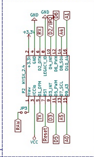
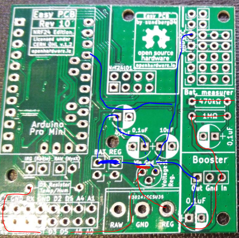
One last thing, I am trying to run a node off a 12Volts battery, can you explain this image below again?
- Will this work for a 5V Promini?
- What are the blue lines? and
- what are the red lines?
-
@sundberg84 Yes you are right I meant to say ProMini not Nano - I have 18 of these PCB - not so happy I have to solder directly to the Arduino - that's exactly what I was avoiding in the first place. Do you have a good relay block sketch that works? Much appreciated if you can help.
One last thing, I am trying to run a node off a 12Volts battery, can you explain this image below again?
- Will this work for a 5V Promini?
- What are the blue lines? and
- what are the red lines?
@eme - its is very strange - I have a big batch here with Rev 10 and i checked atleast 20 of them randomly and all have continutiy between D6/pro mini and D6/MysX. You must have had extreme bad luck and if you check the others it should be ok.
Can you post a picture (close up) of the board not working please showing D6/Pro mini and D6/MysX.
For 12v I would use the prototyping area with a 12 > 5v converter. If you want to use the internal voltage regulator on the pro mini you can connect to RAW but beware that clones will not handle this very good. The specs are 12v but I have seen many bad clones getting destroyed.
I dont really remember this image and from which context this is from. I guess the lines represent different voltages. Adding 12V on reg and a 12>5v regulator on the TO92 footprint will convert and feed the board 5v, but kill the radio...
-
I just checked my batch of Rev 10, random check of the batch checked out OK. I have 20 boards.
-
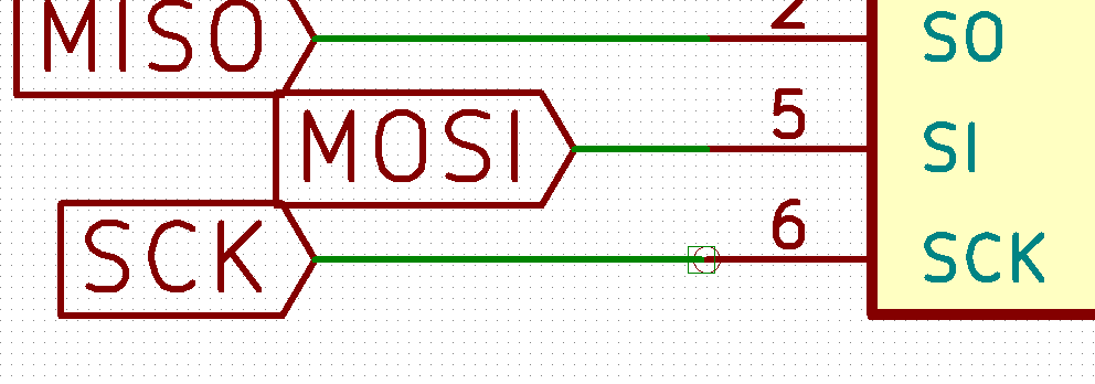
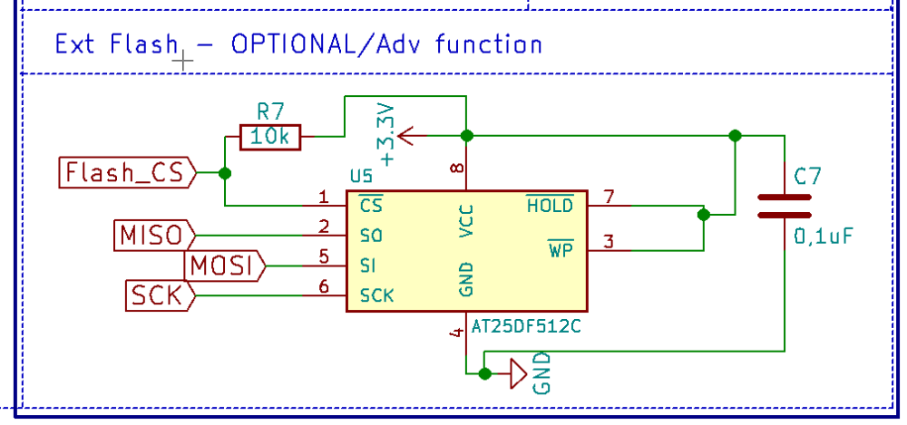
Dear sundberg84, thanks to your really nice and easy mysensors PCB. I ordered ten of them via SEEED and they were delivered today (REV.10). Unfortunally I found some serious bugs in the PCB design regarding the SPI Flash: First pin 6 (SPI SCK) of the flash chip is not connected at all - should be digital IO pin 13 of the Arduino pro mini. Second mistake: the filter capacitor of the flash chip is not between VCC and GND. Third mistake: pin 3 and pin 7 should be connected to VCC and not to the filter capacitor. I changed that on my arrived boards and the flash chip is now working perfectly. Kind regards, JPM
-
I checked the schematic, and:
First mistake: Seems that the schematic is OK, the label for SCK (pin 6) is connected to physical pin 16 which is PCINT13 on the Arduino,
Second mistake: that is a bug, filter capacitor is not connected correctly.
Third mistake: That is also a bug, pin 7 and 3 should be connected to VCC
Now I am going to check the PCB, be back shortly, -
I have now checked the PCB, and you are right @JPM
Pin 6 of the flash chip is not connected at all. No wonder I could not get that to work. Strangely is that the schematic is OK.
Thanks for finding this, I will modify my boards to get them working. -
Sorry for this. The flash has been untested by me. I will fix this asap and upload new files.
The schematics is wrong:
New schematics:
The same error goes for RFM version :(
-
I have now checked the PCB, and you are right @JPM
Pin 6 of the flash chip is not connected at all. No wonder I could not get that to work. Strangely is that the schematic is OK.
Thanks for finding this, I will modify my boards to get them working.@mickecarlsson I found this out and wrote it above that D6 is not connected at all... but it was promptly swept aside cos nobody had reported it before now. I am glad someone else saw it, and that you had the notion to check. D4 is also not connected to the test area. I have been connecting directly to the Nano.
-
@mickecarlsson I found this out and wrote it above that D6 is not connected at all... but it was promptly swept aside cos nobody had reported it before now. I am glad someone else saw it, and that you had the notion to check. D4 is also not connected to the test area. I have been connecting directly to the Nano.
@eme im sorry - since your wrote "The provisions to attach sensors are not correctly marked. D6 doesn't actually connect to D6 pin on the Arduino" I thought you was talking about the MysX connector and not flash. If you mentioned flash I would probably found the issue. They are not talking about D6 but pin 6 on flash which connects to D13 on the Arduino.
Are you sure it's the same problem? Not much that sounds the same.