💬 Easy/Newbie PCB for MySensors
-
I eventually got it to work. I am not using the EasyNewbie to power the load (its for 24volts swimming pool light). Couldn't get the 4th relay to work - not sure why its not responding to the controller. but I noticed some bug with my batch of 16 PCB -
Okay I think I have seen some bugs... my batch of EasyNewbie Rev 10 has some hardware issues - The provisions to attach sensors are not correctly marked. D6 doesn't actually connect to D6 pin on the Arduino (must have failed a via somewhere). I am not sure how many pins are used for the radio and other components, but if you intend to use this for a small project, I will avoid D8 - D13 as they appears to be taken. D1 and D2 are used for the TX & RX so you only have D2 - D6 to play with (more than enough pins for a newbie if you ask me).
@eme good you found the issue. First time I ever hear of a comfirmed PCB hardware bug, so its very rare. Very strange the silkscreen were moved or not aligned correctly as well. From where did you order the PCB?
The documentation states which pins connect to what on the PCB, so make sure you check that out. D9-D13 are used by the radio as in all MySensors projects. D8 for the extra flash. You can find the MysX documentation here as well if you need to find out more about the pins.
-
@Sunberg84 I bought them off Ebay via this very site... The Packing List reads Shipped by Abdera's Sundberg Ostra Gransgatan 2, Lonsboda, Sverige 28070, SE. I believe that's you.
Well I am forced to solder directly to the Nano pins, and so far so good. I think you should help with a 4 relay sketch that works. My appears to be a hit and run, works in the morning and fails after a while. but I am learning as I go. -
@Sunberg84 I bought them off Ebay via this very site... The Packing List reads Shipped by Abdera's Sundberg Ostra Gransgatan 2, Lonsboda, Sverige 28070, SE. I believe that's you.
Well I am forced to solder directly to the Nano pins, and so far so good. I think you should help with a 4 relay sketch that works. My appears to be a hit and run, works in the morning and fails after a while. but I am learning as I go.@eme Thats me - ok, good to know then - but I guess you mean the Mini pins and not Nano since the PCB doesnt support the Nano?
Controller: Proxmox VM - Home Assistant
MySensors GW: Arduino Uno - W5100 Ethernet, Gw Shield Nrf24l01+ 2,4Ghz
MySensors GW: Arduino Uno - Gw Shield RFM69, 433mhz
RFLink GW - Arduino Mega + RFLink Shield, 433mhz -
@eme Thats me - ok, good to know then - but I guess you mean the Mini pins and not Nano since the PCB doesnt support the Nano?
@sundberg84 Yes you are right I meant to say ProMini not Nano - I have 18 of these PCB - not so happy I have to solder directly to the Arduino - that's exactly what I was avoiding in the first place. Do you have a good relay block sketch that works? Much appreciated if you can help.
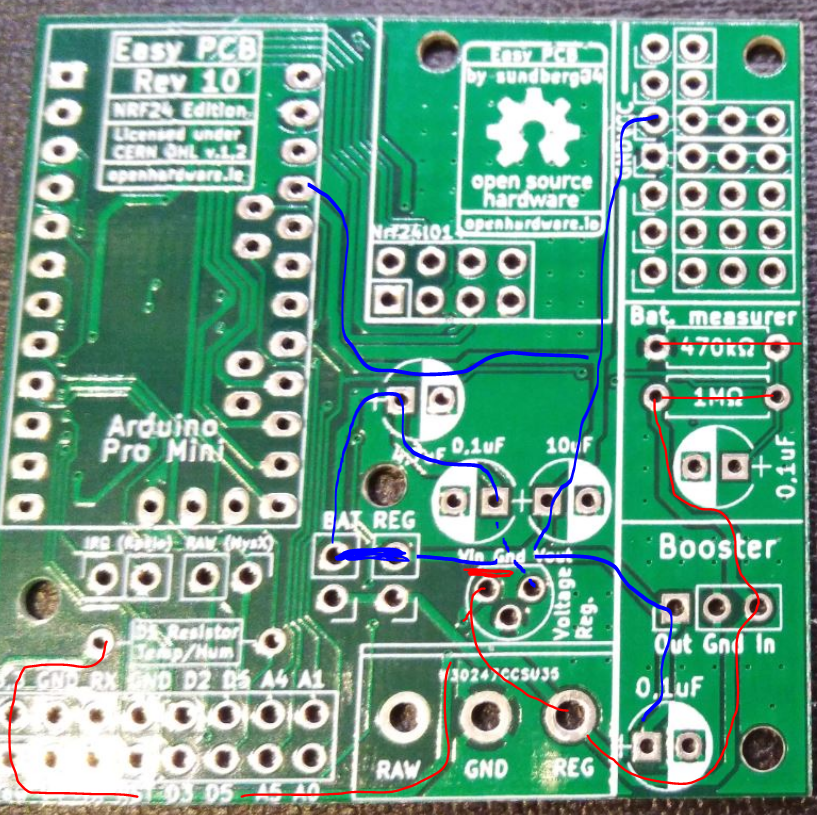
One last thing, I am trying to run a node off a 12Volts battery, can you explain this image below again?
- Will this work for a 5V Promini?
- What are the blue lines? and
- what are the red lines?
-
@sundberg84 Yes you are right I meant to say ProMini not Nano - I have 18 of these PCB - not so happy I have to solder directly to the Arduino - that's exactly what I was avoiding in the first place. Do you have a good relay block sketch that works? Much appreciated if you can help.
One last thing, I am trying to run a node off a 12Volts battery, can you explain this image below again?
- Will this work for a 5V Promini?
- What are the blue lines? and
- what are the red lines?
@eme - its is very strange - I have a big batch here with Rev 10 and i checked atleast 20 of them randomly and all have continutiy between D6/pro mini and D6/MysX. You must have had extreme bad luck and if you check the others it should be ok.
Can you post a picture (close up) of the board not working please showing D6/Pro mini and D6/MysX.
For 12v I would use the prototyping area with a 12 > 5v converter. If you want to use the internal voltage regulator on the pro mini you can connect to RAW but beware that clones will not handle this very good. The specs are 12v but I have seen many bad clones getting destroyed.
I dont really remember this image and from which context this is from. I guess the lines represent different voltages. Adding 12V on reg and a 12>5v regulator on the TO92 footprint will convert and feed the board 5v, but kill the radio...
-
I just checked my batch of Rev 10, random check of the batch checked out OK. I have 20 boards.
-
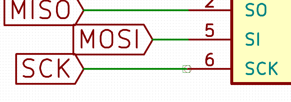
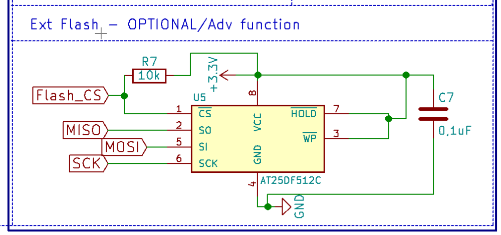
Dear sundberg84, thanks to your really nice and easy mysensors PCB. I ordered ten of them via SEEED and they were delivered today (REV.10). Unfortunally I found some serious bugs in the PCB design regarding the SPI Flash: First pin 6 (SPI SCK) of the flash chip is not connected at all - should be digital IO pin 13 of the Arduino pro mini. Second mistake: the filter capacitor of the flash chip is not between VCC and GND. Third mistake: pin 3 and pin 7 should be connected to VCC and not to the filter capacitor. I changed that on my arrived boards and the flash chip is now working perfectly. Kind regards, JPM
-
I checked the schematic, and:
First mistake: Seems that the schematic is OK, the label for SCK (pin 6) is connected to physical pin 16 which is PCINT13 on the Arduino,
Second mistake: that is a bug, filter capacitor is not connected correctly.
Third mistake: That is also a bug, pin 7 and 3 should be connected to VCC
Now I am going to check the PCB, be back shortly, -
I have now checked the PCB, and you are right @JPM
Pin 6 of the flash chip is not connected at all. No wonder I could not get that to work. Strangely is that the schematic is OK.
Thanks for finding this, I will modify my boards to get them working. -
Sorry for this. The flash has been untested by me. I will fix this asap and upload new files.
The schematics is wrong:
New schematics:
The same error goes for RFM version :(
-
I have now checked the PCB, and you are right @JPM
Pin 6 of the flash chip is not connected at all. No wonder I could not get that to work. Strangely is that the schematic is OK.
Thanks for finding this, I will modify my boards to get them working.@mickecarlsson I found this out and wrote it above that D6 is not connected at all... but it was promptly swept aside cos nobody had reported it before now. I am glad someone else saw it, and that you had the notion to check. D4 is also not connected to the test area. I have been connecting directly to the Nano.
-
@mickecarlsson I found this out and wrote it above that D6 is not connected at all... but it was promptly swept aside cos nobody had reported it before now. I am glad someone else saw it, and that you had the notion to check. D4 is also not connected to the test area. I have been connecting directly to the Nano.
@eme im sorry - since your wrote "The provisions to attach sensors are not correctly marked. D6 doesn't actually connect to D6 pin on the Arduino" I thought you was talking about the MysX connector and not flash. If you mentioned flash I would probably found the issue. They are not talking about D6 but pin 6 on flash which connects to D13 on the Arduino.
Are you sure it's the same problem? Not much that sounds the same.
-
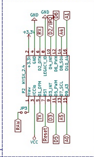
@sundberg84 if you look at the schematic you have connected MySX pin 10 to D2, but according to the spec for the MySX 2.4 it should go to D4.
-
@sundberg84 if you look at the schematic you have connected MySX pin 10 to D2, but according to the spec for the MySX 2.4 it should go to D4.
@mickecarlsson - I understand your point, and I have changed this back and forth and also asked @Anticimex becuase its a but unclear in the documentation.
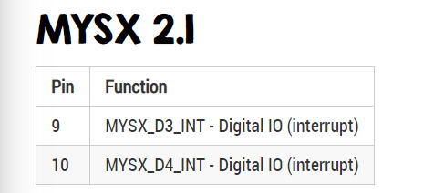
MysX 9 + 10 should go to a Digital IO with interrupt, and D2 and D3 is the only pins with interrupts on mini.
I guess you are refering to Mysx_D3_INT but this is the MysX name.
Controller: Proxmox VM - Home Assistant
MySensors GW: Arduino Uno - W5100 Ethernet, Gw Shield Nrf24l01+ 2,4Ghz
MySensors GW: Arduino Uno - Gw Shield RFM69, 433mhz
RFLink GW - Arduino Mega + RFLink Shield, 433mhz -
@mickecarlsson - I understand your point, and I have changed this back and forth and also asked @Anticimex becuase its a but unclear in the documentation.
MysX 9 + 10 should go to a Digital IO with interrupt, and D2 and D3 is the only pins with interrupts on mini.
I guess you are refering to Mysx_D3_INT but this is the MysX name.
@sundberg84 @mickecarlsson
It is important to remember that MYSX is agnostic from any devices.
Any names in MYSX pins bear no correlation to any device specific pin naming, so D3 and D4 mentioned on pin 9 and 10 has nothing to to with any D3 or D4 on any MCU.
If you look here, you will find that the 'A' and 'D' notation is simply an indicator of the pin function (analog or digital) and it simply increments with the pin number, so the lowest analog or digital pin number in the MYSX connector will start at '1' and then increment as the pin number increments with '2' for the next digital being on pin '6'.
Also note that since some pins are deprecated in MYSX 2.x, MYSX 2.x analog pins starts with 'A3'. -
I was wondering if there are any CAD files for corner through hole size/locations for Rev 10? Trying to design enclosure for it.
@birinderk SHould be easy enough to measure it with a caliper. That's what I did with the earlier revisions of the board (rev 8 & 9). They had pretty much the same hole spacing. Here are a few of the enclosures/sensor cases that I did that fit the rev 8 and 9's.
https://www.thingiverse.com/thing:2186286
https://www.thingiverse.com/thing:3339158
https://www.thingiverse.com/thing:2904969 -
I was wondering if there are any CAD files for corner through hole size/locations for Rev 10? Trying to design enclosure for it.
-
Does anyone know where we can find the write ups for old revisions? i have a bunch of Rev9 boards that, now that i have restarted these projects after a year break i cant remember the write ups for them....