Skip to content
  • MySensors
  • OpenHardware.io
  • Categories
  • Recent
  • Tags
  • Popular
Skins
  • Light
  • Brite
  • Cerulean
  • Cosmo
  • Flatly
  • Journal
  • Litera
  • Lumen
  • Lux
  • Materia
  • Minty
  • Morph
  • Pulse
  • Sandstone
  • Simplex
  • Sketchy
  • Spacelab
  • United
  • Yeti
  • Zephyr
  • Dark
  • Cyborg
  • Darkly
  • Quartz
  • Slate
  • Solar
  • Superhero
  • Vapor

  • Default (No Skin)
  • No Skin
Collapse
Brand Logo
  1. Home
  2. OpenHardware.io
  3. 💬 Sensebender Gateway

💬 Sensebender Gateway

Scheduled Pinned Locked Moved OpenHardware.io
mysensorsgatewaysamd
382 Posts 59 Posters 151.2k Views 53 Watching
  • Oldest to Newest
  • Newest to Oldest
  • Most Votes
Reply
  • Reply as topic
Log in to reply
This topic has been deleted. Only users with topic management privileges can see it.
  • tbowmoT Offline
    tbowmoT Offline
    tbowmo
    Admin
    wrote on last edited by
    #2

    Almost ready for a last roll of prototype.. I've updated github with latest changes, if anyone cares to have a look at it, and give me some feedback on it, then it is now! during Easter, I will (hopefully) do the last prototype spin!

    GertSandersG kalinaK 2 Replies Last reply
    2
    • tbowmoT tbowmo

      Almost ready for a last roll of prototype.. I've updated github with latest changes, if anyone cares to have a look at it, and give me some feedback on it, then it is now! during Easter, I will (hopefully) do the last prototype spin!

      GertSandersG Offline
      GertSandersG Offline
      GertSanders
      Hardware Contributor
      wrote on last edited by GertSanders
      #3

      @tbowmo

      hi Thomas, I was looking at the schematic on OpenHardware.io an![alt text](image url)d saw that you pull WP and HOLD to low permanently. By pulling WP low, doesn't that make the write protect active all the time (blocking any writing) ?

      0_1457770202025_Screen Shot 2016-03-12 at 09.07.51.png

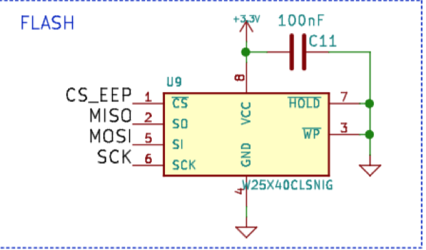
      I believed we needed to pull WP high to allow writing to the flash. If I'm wrong I would like to know, so I can correct my schematic because I'm making a board that also uses the flash.

      Update: I saw that your new schematic no longer has this flash (SD card is better).

      1 Reply Last reply
      0
      • scalzS Offline
        scalzS Offline
        scalz
        Hardware Contributor
        wrote on last edited by scalz
        #4

        @tbowmo : cool, your project is tempting :)
        For programming it, I guess you recommand an atmel ice??? I am searching if I could use my st link v2 but not sure ( maybe I dreamt of this but I thought I read a link somewhere about using st link with atmel m0..). I will need something as now I am waiting my homemade atsam node pcb, because of you and Gert :laughing:

        Edit: it seems that it could be possible to flash st link to use cmsis (which is the protocol used to flash atsam if I understand right) but don't know if i want to do this. So maybe others cmsis jtag cheap programmer could work ...I read that it could be possible to use another "zero" like to program an homemade one, or why not an atsam10 explained..Or more simple atmel ice, maybe I will choose this easy/less bad suprise way...

        1 Reply Last reply
        0
        • tbowmoT Offline
          tbowmoT Offline
          tbowmo
          Admin
          wrote on last edited by
          #5

          @GertSanders

          Oops.. I think it's an old schematic from the first iterations of the project.. the onboard flash is now exchanged with an SD-CARD reader instead..

          I'll update the PDF once I get to my own computer (which should be Sunday evening)

          1 Reply Last reply
          0
          • tbowmoT Offline
            tbowmoT Offline
            tbowmo
            Admin
            wrote on last edited by tbowmo
            #6

            @GertSanders

            Just checked github, and it seems that it does have the correct revision of the schematics

            https://github.com/tbowmo/MySensorGW/blob/master/MysensorsGW.pdf

            And I have updated the schematics at openhardware as well (Forgot that it doesn't do automatic refresh from GH yet)

            GertSandersG 1 Reply Last reply
            0
            • tbowmoT tbowmo

              @GertSanders

              Just checked github, and it seems that it does have the correct revision of the schematics

              https://github.com/tbowmo/MySensorGW/blob/master/MysensorsGW.pdf

              And I have updated the schematics at openhardware as well (Forgot that it doesn't do automatic refresh from GH yet)

              GertSandersG Offline
              GertSandersG Offline
              GertSanders
              Hardware Contributor
              wrote on last edited by
              #7

              @tbowmo
              Hi Thomas, Github did have the correct schematic, my remark was based on the schematic on OpenHardware.io (which is now also updated).

              But my question remains: when using the flash memory, what do you normally do with WP and HOLD ? Should they be pulled up or down ?

              tbowmoT 1 Reply Last reply
              0
              • GertSandersG GertSanders

                @tbowmo
                Hi Thomas, Github did have the correct schematic, my remark was based on the schematic on OpenHardware.io (which is now also updated).

                But my question remains: when using the flash memory, what do you normally do with WP and HOLD ? Should they be pulled up or down ?

                tbowmoT Offline
                tbowmoT Offline
                tbowmo
                Admin
                wrote on last edited by
                #8

                @GertSanders

                Depends on if they are active high, or active low.. In this case they where active low, so it actually was an error in the schematics, as it will writeprotect the flash chip.

                @tekka please be aware of this, when you try to use the external flash in the bootloader on the dev board that I sent you..

                GertSandersG 1 Reply Last reply
                0
                • tbowmoT tbowmo

                  @GertSanders

                  Depends on if they are active high, or active low.. In this case they where active low, so it actually was an error in the schematics, as it will writeprotect the flash chip.

                  @tekka please be aware of this, when you try to use the external flash in the bootloader on the dev board that I sent you..

                  GertSandersG Offline
                  GertSandersG Offline
                  GertSanders
                  Hardware Contributor
                  wrote on last edited by
                  #9

                  @tbowmo
                  Thanks, in my case they are also active low, so I pull them to VCC.

                  1 Reply Last reply
                  0
                  • tbowmoT Offline
                    tbowmoT Offline
                    tbowmo
                    Admin
                    wrote on last edited by
                    #10

                    @GertSanders

                    Actually I think that it's more or less an industry standard, that they are active low, Must have had a brain meltdown when I made the schematics back then :)

                    1 Reply Last reply
                    0
                    • tbowmoT Offline
                      tbowmoT Offline
                      tbowmo
                      Admin
                      wrote on last edited by
                      #11

                      @scalz

                      It seems that the CMSIS is a Cortex communication protocol, so all cortex debuggers should use that protocol?

                      Are you sure that the st link, doesn't support it?

                      1 Reply Last reply
                      0
                      • scalzS Offline
                        scalzS Offline
                        scalz
                        Hardware Contributor
                        wrote on last edited by
                        #12

                        @tbowmo: thx for reply. Yes I have understood the same thing, so it should work... I will try with my stlink (st brand) asap I will receive my pcb.
                        Talking about stlink, I have just ordered this, very curious.. http://www.aliexpress.com/item/Free-shipping-1pcs-mini-ST-LINK-V2-ST-LINK-STLINK-STM8-STM32-emulator-download-super-protection/32600512506.html?spm=2114.01010208.3.1.1O5urT&ws_ab_test=searchweb201556_9,searchweb201602_1_505_506_503_504_10034_10020_502_10001_10002_10017_10010_10005_10006_10011_10003_10021_10004_10022_10009_10008_10018_10019,searchweb201603_3&btsid=0dfc1060-5064-466c-8071-ac0bab24a988
                        seriously??so cheap compared to some tools..if it can do the job, could be interesting!
                        There is also the nice IBDAP, cheap alternative to ice :
                        https://www.adafruit.com/products/2764
                        maybe you already know, I have not tested this yet, but seems very simple/useful tool:https://github.com/ataradov/edbg

                        1 Reply Last reply
                        0
                        • tbowmoT Offline
                          tbowmoT Offline
                          tbowmo
                          Admin
                          wrote on last edited by
                          #13

                          @scalz
                          That is cheap.. Perhaps I should buy one, just for the fun of it, and try it out :)

                          I have my jtagice3 though, and it's working fine.. (Even though they don't have the correct cortex-m0 debug port pin layout..)

                          1 Reply Last reply
                          0
                          • nemikN Offline
                            nemikN Offline
                            nemik
                            Hardware Contributor
                            wrote on last edited by
                            #14

                            I've been using those cheap $3 ST-Link adapters for flashing ARM cortex chips with OpenOCD, using SWD pins. They're fantastic and work very well.

                            1 Reply Last reply
                            0
                            • nick van alstN Offline
                              nick van alstN Offline
                              nick van alst
                              wrote on last edited by
                              #15

                              i really like this idea, i'm getting a bit tierd of having the mysensors gateway connected through a breadboard.

                              how far is it? i saw your comment that it is almost ready for last prototype, is this board fully functional?
                              Plus, will it be able to act as a Serial/Ethernet/MQTT gateway? or only 1 of these?

                              And if it is ready, is there a place to order them, or just send the files to a PCB company?

                              1 Reply Last reply
                              0
                              • tbowmoT Offline
                                tbowmoT Offline
                                tbowmo
                                Admin
                                wrote on last edited by
                                #16

                                I'm still waiting for the last prototype pcb's to arrive.

                                Depending on the sketch you load it with, it can be a serial, ethernet or MQTT gateway. It has native USB in the atsam, and a connector for a w5100 module.

                                Besides that it will have SD card for local storage of sensor data, so it could in theory operate without a controller at all..

                                TheoLT 1 Reply Last reply
                                0
                                • tbowmoT tbowmo

                                  I'm still waiting for the last prototype pcb's to arrive.

                                  Depending on the sketch you load it with, it can be a serial, ethernet or MQTT gateway. It has native USB in the atsam, and a connector for a w5100 module.

                                  Besides that it will have SD card for local storage of sensor data, so it could in theory operate without a controller at all..

                                  TheoLT Offline
                                  TheoLT Offline
                                  TheoL
                                  Contest Winner
                                  wrote on last edited by
                                  #17

                                  @tbowmo Can you give some details about the final dimensions on the board? I want to start the woodworking on the casing for my current gateway. But I'll make sure your prototype fits in as well.

                                  I can't wait 'till this one goes to production. Great work, I'm impressed.

                                  1 Reply Last reply
                                  0
                                  • tbowmoT Offline
                                    tbowmoT Offline
                                    tbowmo
                                    Admin
                                    wrote on last edited by
                                    #18

                                    @TheoL

                                    The base board is 5x5 cm, but if you use nrf modules they will protrude over the edge of the PCB. Rfm69 is soldered to the bottom so they won't add to the dimensions. W5100 will probably make the base a few mm wider and longer (depending on the module..).
                                    Design files are available at GH, so you can check the dimensions yourself

                                    TheoLT 1 Reply Last reply
                                    0
                                    • tbowmoT tbowmo

                                      @TheoL

                                      The base board is 5x5 cm, but if you use nrf modules they will protrude over the edge of the PCB. Rfm69 is soldered to the bottom so they won't add to the dimensions. W5100 will probably make the base a few mm wider and longer (depending on the module..).
                                      Design files are available at GH, so you can check the dimensions yourself

                                      TheoLT Offline
                                      TheoLT Offline
                                      TheoL
                                      Contest Winner
                                      wrote on last edited by
                                      #19

                                      @tbowmo Thanx for your fast reply. It's a great size. I'll create a mockup of it with cardboard. It'll give me a better visualization when I make the housing. Just a final question. I'm guessing I won't be able to stick an Arduino ethernet shield on it right?

                                      1 Reply Last reply
                                      0
                                      • tbowmoT Offline
                                        tbowmoT Offline
                                        tbowmo
                                        Admin
                                        wrote on last edited by
                                        #20

                                        @TheoL

                                        the GW is not the same dimensions as arduino, so Arduino shields would not fit :)

                                        A mini w5100 board like this would fit..

                                        Also, see this "old" forum post about the GW device, there is some conceptual pictures of how it would look like with nrf and w5100 attached.

                                        1 Reply Last reply
                                        0
                                        • tbowmoT Offline
                                          tbowmoT Offline
                                          tbowmo
                                          Admin
                                          wrote on last edited by
                                          #21

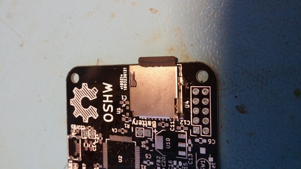
                                          Received a new prototype from dirtypcbs the other day

                                          0_1461067276748_gw1.jpg

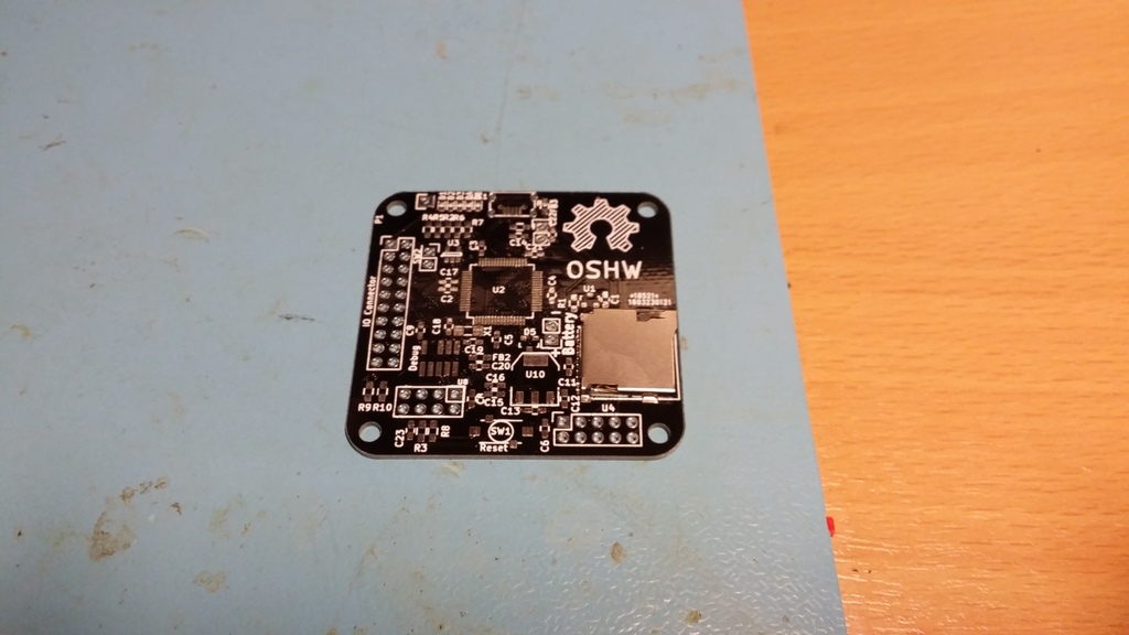
                                          I have only come to the point where the SD Card reader is mounted, as I wanted to try the mechanics out :)

                                          0_1461067334506_gw3.jpg

                                          Currently I'm lacking time for finishing it within the next 2-3 weeks.. If someone knows how to slow down time around you, without being slowed down yourself, please tell me how to achieve it :) (Too many high priority tasks at the moment..)

                                          G GertSandersG 2 Replies Last reply
                                          5
                                          Reply
                                          • Reply as topic
                                          Log in to reply
                                          • Oldest to Newest
                                          • Newest to Oldest
                                          • Most Votes


                                          20

                                          Online

                                          11.7k

                                          Users

                                          11.2k

                                          Topics

                                          113.0k

                                          Posts


                                          Copyright 2019 TBD   |   Forum Guidelines   |   Privacy Policy   |   Terms of Service
                                          • Login

                                          • Don't have an account? Register

                                          • Login or register to search.
                                          • First post
                                            Last post
                                          0
                                          • MySensors
                                          • OpenHardware.io
                                          • Categories
                                          • Recent
                                          • Tags
                                          • Popular