💬 In Wall AC/DC Pcb for MySensors
-
After quite a bit of abuse from resoldering components as I completely screwed up the order of things to get soldered I got the first couple of AC nodes running. These will be discarded once I get new Mini Pros to make fresh nodes without messing them up too much with my hot soldering iron. Been running them for 12 hours yesterday and everything seems fine. Great work on designing the PCBs @Sundberg84!
One tip is to cool the thermal cutoffs well while soldering. I broke the first one cooling it with pliers + aligator clip. Next I used water soaked paper around components and legs with great results. Just be mindful not to soak "the wrong components".
<blockquote class="imgur-embed-pub" lang="en" data-id="a/DBln7"><a href="//imgur.com/DBln7"></a></blockquote><script async src="//s.imgur.com/min/embed.js" charset="utf-8"></script> -
After quite a bit of abuse from resoldering components as I completely screwed up the order of things to get soldered I got the first couple of AC nodes running. These will be discarded once I get new Mini Pros to make fresh nodes without messing them up too much with my hot soldering iron. Been running them for 12 hours yesterday and everything seems fine. Great work on designing the PCBs @Sundberg84!
One tip is to cool the thermal cutoffs well while soldering. I broke the first one cooling it with pliers + aligator clip. Next I used water soaked paper around components and legs with great results. Just be mindful not to soak "the wrong components".
<blockquote class="imgur-embed-pub" lang="en" data-id="a/DBln7"><a href="//imgur.com/DBln7"></a></blockquote><script async src="//s.imgur.com/min/embed.js" charset="utf-8"></script>@johmei - thank you! All tips for future revisions are appreciated! Let me know if I can do anything better and good luck with your nodes!
-
I think the nodes seem to run really well with minimal produced heat. Do you think there will be a 3D case design for the latest version PCB? Unfortunately I have no knowledge in 3D design to contribute.
@johmei - sorry, its been on my list as you probably see above.
I will try to make one asap! -
Finally I made the changes to the silk-screen so the orientation of the LE33 and Dallas temp sensor is right.
Project updated and sent new revision to PCB manufacturer. The right revision if you want to buy should be Rev 4 which is the latest files (PCB Rev 4.1) -
Hello,
i´have purchased the in wall pcb rev.3.1.
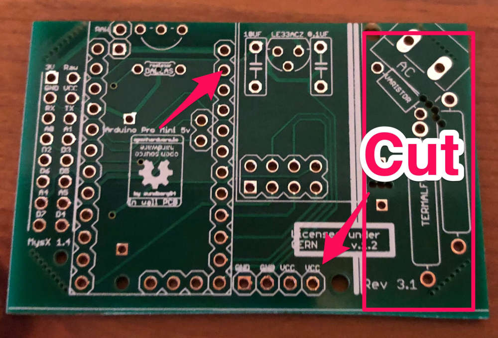
Now i´m want to cut up the right part of the pcb and powering the pcb with 5V power adapter.
Why is the VCC pin (lower arrow) with the arduino GND pin (upper arrow) connectet?
The GND pin lower side is connectet to arduino VCC pin, is that a mistake?
I´m think the print vcc and ground are reversed. -
Hello,
i´have purchased the in wall pcb rev.3.1.
Now i´m want to cut up the right part of the pcb and powering the pcb with 5V power adapter.
Why is the VCC pin (lower arrow) with the arduino GND pin (upper arrow) connectet?
The GND pin lower side is connectet to arduino VCC pin, is that a mistake?
I´m think the print vcc and ground are reversed.@the-holgi Hi - hmm, this is an old revision and there might be misstakes as you describe. The current version is 4.1. Im traveling with work and dont have the documentation with me - but it should be quite easy to figure out if vcc and gnd are reversed by probing it with a multimeter. This PCB was not made to cut like this, but it might work - you have to try.
-
Just FYI: I have ordered 20pcb in January, and even though they are 4.1rev (pcbway), the le33a voltage regulator's silk screen still points to the wrong direction (flat side outwards). Also the second picture here mentions 4.1 rev, but I think this is an older rev. flat side outwards will connect the le33a Vin 5V leg to the Vin for the NRF2.4 in the 4.1 rev. Or the other way is that the orientation is good, but then it should be on the other side of the board :) So if it would be on the same side like the capacitors, it would be ok. (I have realized this after the third node built up wrongly.. :) )
Do you know if the le33a gets 5V to the 3v3 leg, will it survive? Other components? -
Just FYI: I have ordered 20pcb in January, and even though they are 4.1rev (pcbway), the le33a voltage regulator's silk screen still points to the wrong direction (flat side outwards). Also the second picture here mentions 4.1 rev, but I think this is an older rev. flat side outwards will connect the le33a Vin 5V leg to the Vin for the NRF2.4 in the 4.1 rev. Or the other way is that the orientation is good, but then it should be on the other side of the board :) So if it would be on the same side like the capacitors, it would be ok. (I have realized this after the third node built up wrongly.. :) )
Do you know if the le33a gets 5V to the 3v3 leg, will it survive? Other components?@yoshida - sorry, I will have a check. Either its the wrong files or it not been update at the factory.
Im sorry, I dont know if it will survive. You have to test it. -
@yoshida - sorry, I will have a check. Either its the wrong files or it not been update at the factory.
Im sorry, I dont know if it will survive. You have to test it.I was able to do a photo, so the dallas temp, and le33 "mask" is on the opposite side, I think this is the problem. (in your example pictures they are on the good side)
No worries, I use currently the newbie pcbs for light switching,
