💬 Roller Shutter Node
-
I just realised: he is not using the two relays to give two AC sources, but uses them to switch a motor.
I was still in my mind thinking about my relay board (not published) which gives a contact with 220V when relay is closed and is AC free when relay is open.
But I will check his BOM to see which relays @scalz is using. They are smaller then the popular SONGLE relays and the pin layout is better for keeping AC away from low voltage circuitry.
@GertSanders Please inform me of those he uses when you find them. I too like the look of those on his board. Does your module use solid state relays?
-
hi guys :)
@Tmaster thx I'm glad ;) I'm not lucky this is so compact, so I couldn't have both footprint (rfm and nrf), argh so I made two rev. Don't ask me why, I still don't know, I'm going crazy :laughing:
@GertSanders schematic is already there. arg, I thought it was enough readable. what do you want to know about AC?
Here, for protecting shutter motor I had to put relays in serie.
So there is one SPST NO for "power". When enabled, if I remember right, it moves UP. Send logic 1 to the 2nd relay, and as it is SPDT it will go DOWN. Disable the first one, no more juice...
if motor is AC, the 12_220 pad need to be connected to one LIVE.
if motor is DC, 12_220 need to be connected to your DC source.Relays I'm using are well known OMRON. G5Q. I choosed them exactly for what you said, size and footprint. Nice price at tme, I have a bunch of them ;) No ad :) I have other more powerful 16a too, for a special multi relays board...
I have modified a little bit my thing. Boards are ordered. I will try to upload asap. I'm a bit busy and would like to check few things before, you know..Oh, and I have other cool projects ongoing, I hope you will like them ;)
-
@GertSanders Please inform me of those he uses when you find them. I too like the look of those on his board. Does your module use solid state relays?
@Samuel235
My board is using the cheap Songle relays (5V switches 10A 220VAC).In the mean time I found out he is using G5Q by OMRON series. They have a Panasonic equivalent at Aliexpress, I will try those.
-
hi guys :)
@Tmaster thx I'm glad ;) I'm not lucky this is so compact, so I couldn't have both footprint (rfm and nrf), argh so I made two rev. Don't ask me why, I still don't know, I'm going crazy :laughing:
@GertSanders schematic is already there. arg, I thought it was enough readable. what do you want to know about AC?
Here, for protecting shutter motor I had to put relays in serie.
So there is one SPST NO for "power". When enabled, if I remember right, it moves UP. Send logic 1 to the 2nd relay, and as it is SPDT it will go DOWN. Disable the first one, no more juice...
if motor is AC, the 12_220 pad need to be connected to one LIVE.
if motor is DC, 12_220 need to be connected to your DC source.Relays I'm using are well known OMRON. G5Q. I choosed them exactly for what you said, size and footprint. Nice price at tme, I have a bunch of them ;) No ad :) I have other more powerful 16a too, for a special multi relays board...
I have modified a little bit my thing. Boards are ordered. I will try to upload asap. I'm a bit busy and would like to check few things before, you know..Oh, and I have other cool projects ongoing, I hope you will like them ;)
@scalz
No worries about the schematic. I was just confused (but it is clear now). Do you have a link for the relays ? I can find equivalents from Panasonic on the Aliexpress site. Not sure what vendor you mean with TME (url?)I always look forward to your projects :-)
-
@GertSanders I'm reassured ;) I try to keep things understable but sometimes my brain is confused lol
Relays I'm using:
http://www.tme.eu/en/details/g5q-1-eu-5dc/miniature-electromagnetic-relays/omron/g5q-1-eu-5vdc/
http://www.tme.eu/en/details/g5q-1a-eu-5dc/miniature-electromagnetic-relays/omron/g5q-1a-eu-5vdc/
The cheaper I found at a trusted source. nice isn't it? -
@GertSanders a last note..that's not my very last schematic rev. On this previous one, you can see I was protecting globally the board with a 5Amp fuse, good for relays here (shutter motor don't use so much), but what about hilink?? not rated for 5a at all! So on bottom, I have added a smd fuses for the hilink only. So there are two fuses on my board now.
Link of the smd fuse :
http://www.mouser.com/ds/2/9/MF2410 Datasheet2013-247737.pdf
I never tried this one so I will tell you if it works well. I have 0.8 and 1amp ref. I think it's largely enough secure...varistor, temp sensor, two fuses...lol I don't know if there are so much things in commercial products..If there is a problem on the board, lot of chance there is a bigger problem somewhere else lol -
Hey there :)
sorry for delay, busy busy time..
Just to say i have uploaded latest pics , and I will try to make a vid of the thing in action as soon as i can..
See you soon! -
hi
my node is still working well..i'm trying to reorganize my priority, I'm enough confident to release :blush:
for the report, I don't remember if I explained how i did my acs calibration so..Here a pic of an homemade load, don't laugh, it can be useful :)
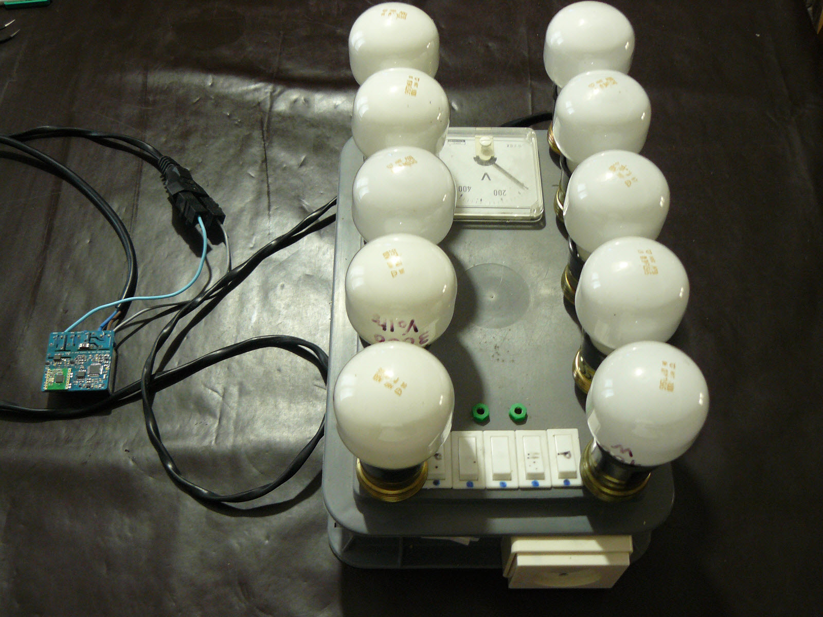
I can power 1 to 5 incandescent bulbs separately on a row, and there is also a switch to power completely the other row. So I was able to measure 0-1000W by 100W step. cool :)And the report after calibrating a bit opamp circuit
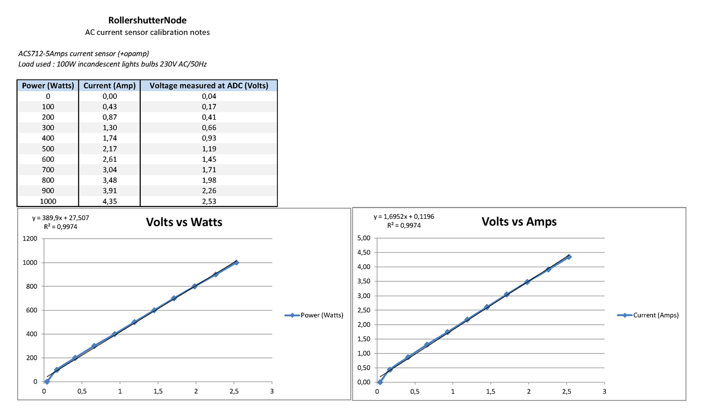
So you can see that's pretty nice.
I know there could be some debate about the way I decided to do the endstop monitoring. I could have used other ways than acs sensors. but after footprint evaluation, cost, versatility etc..I preferred imho this way.
Plus, like this, by using the opamp, I can have a nice curve for a 3V adc, keeping atmel 3v, and saving some uc cycle without doing sampling for 50hz etc...and I can use some fast adc for faster.. -
@scalz said:
@tonnerre33 yep. you're right, it's cms I'm sorry :disappointed: I think.. good luck to fit everything with arduino mini in wall.
About the cutoff, I replaced this by a simple temperature sensor for monitoring. imho, i have two fuses onboards + varistor, enough for me comparing to some commercial products. If it burns you have a big problem somewhere!! But sure it's better to know what you do, thermal fuses is good ;)About the cutoff, i understand you replaced this by a simple temperature sensor but do you cut the primary of the AC source if the temperature is too hight ?
If we only cut the ouput relays and the problem came from the AC source, how we cut the power for stop the overheating ?Thx for your answers and thx for this project ;)
-
@tonnerre33 : and how do you protect your thermofuse? :laughing: I'm joking :) I think it's a bit redundant, protection on protection for this project, especially..
But that's an interesting question, I will try to answer how I have made my choice, I hope to not miss a point, and don't forget it is imho ;)About the fuse:
- if you look at the board (topview), you will see that's too tight to put the thermofuse. And I prefer AC isolated on pcb side. The previous rev of this board was few millimeters more wide, and didn't fit well first. Now it's better
- how to secure, I thought? what if hilink fails (paranoid mode as it's a nice module)? So I decided to put a dedicated fast blow fuse for hilink. Right, no temperature! (Note : there is another 5amps fuses but it's for handling relays).
- Two choice, heu no 3 in fact.
I could use rfm to monitor hilink temp...could work, not the best precision, but that would need I put rfm69 under hilink to be precise enough as I want. Maybe paranoid on EMI etc..but I didn't wanted to put the radio under hilink, and for antenna performance.
So..a CTN? I was using this on the previous rev, under hilink.
For this one, I have decided to use onewire sensor glued on hilink side. nice too.
But..you're still right, no temp cutoff! damn!! But:
- why would the temperature increase??? over current somewhere? on a bad hilink or something else? etc..
The hilink fuse should be already dead at this moment! If I remember well the ref I use is a 500mah, there is 1A variant too. For lightnings storm etc.. there is also a varistor. - and what happens if temp increase? For thermofuse, are you notified if it happens? or a bit before it happens? Or can you predict it for weeks? In my case, I like the idea to be able to monitor/detect weeks before, than waiting it burn in the wall! in case the board starts to heat more than usual,
- the hilink is already well protected.
- what else :smile: ah yes! I have millings on the boards, respected creepage/clearance..
Now, I'm curious, I would like to know how can I make my board burning in the wall? I would like to try..I think my main electric system will trigger too..
Very personal opinion, perhaps i've not answered completely to your question...but i've answered why I thought it was redundant :)
-
@Nca78 : I prefer to answer this here as the question was related to shutter
@Nca78 said:
@scalz on your board you use relays that are much bigger than those tiny SSRs, in the end it probably gives the same result for the space used on the board, and as you have the radio on the other side the depth difference is not very big, just 2mm from the plastic at the base of the connectors.
The board you're talking on the other topic is different.For multiple reasons, that's not the best choice to use SSR for shutters. commercial products use spst+spdt too, I guess.
For relays choice: with no snubber, 5amps will be less good than a 10amps.About footprint constraints, these two boards are not comparable.
If it's for a shutter node, on mine there is a current sensor, relay driver, signing authentication chip, flash eeprom for memory etc..and I respect all clearance and creepage, no radio near AC nor other traces, all components on one side for maintenance..
Like I said, I wish good luck to someone who want to make my board using arduino mini + hilink with all my requirements, same size and thickness. You can't do small tight things with big things or I want to see creepage/clearance results ;) -
It's ok, i haven't seen the fuse in the primary of the hilink ;)
with this fuse, the protection is guaranteed, then you don't need termofuse in this project :+1:
thanx for answer how you made your choice and i hope the release will arrive soon :) -
@scalz I agree with you it's not the best choice, I just want to try it anyway and see how it behaves. The configuration you use is probably the one used in commercial products, but my neighbour has some electric shutters with fibaro modules and they are really tiny, I wonder what relays they use. They have an external antenna (a wire) so it probably eases the internal design, they use a transformerles design, but I still don't get how they can fit relays inside and respect clearance/creepage.
I'm tempted with your board, but like many others the SMD components are putting me off at the moment. Wonder if this type of board would not be a good candidate for an ESP8266 module ?
It would take space similar to a radio module, but without any routing needed to connect to atmega. (and the castellated pins are not very hard to solder :)) -
@Nca78 oki it's good to experiment by yourself you're right :) and if you do something better, sure i would use it ;) I'm not dumb!
for esp8266, i thought about it too.
First, I'm not a fan of wifi for rollershutter, it's like a door..I prefer something more secured with atmel/rfm/signing. But i have tried in eagle to see.
footprint was not really better! just looking at the topview, it's difficult to make smaller..as you can see with @dpressle board, which is nice design though, but 5x5, not same features, and i don't know about thickness, antenna near traces etc..so not same goals as I said.for fibaro modules, I don't have one so i can't tell, I know they are good in miniaturization. but I'm pretty sure they are using transformless, with a very tight, controlled and professional design etc..but my design is opensource work (almost for the moment) with a current sensor which can add some versatility who knows.
Maybe not so easy to handsolder for noobs, i can agree.
I could have used 0603, instead i kept 0805. in case middle experienced people would build it with moderate tools. even a noob who want to learn and know a bit about AC. On my side, no glasses and i don't need a magnifier with 0805, nor 0603 but it's easier with one. Maybe lucky. Try maybe you don't need it too guys, with little patience, pratice and fun :) I admit I'm not noob but I'm not former electronician.A trick: if not really friendly with smd, and need some boards, a stencil costs 15-20$, it's reusable, boost the job, and if you don't have reflow oven, there are multiple alternative like using your solder iron as solder paste is already applied, or hot gun etc.
taste and colours sometimes... :)
-
@Samuel235 Elecrow when i order pcb, or oshstencils.com is great too
-
@Samuel235 Elecrow when i order pcb, or oshstencils.com is great too
-
@Samuel235 Elecrow when i order pcb, or oshstencils.com is great too
-
Hey guys :)
this time is time for update ;)
rfm69 version is uploaded. Added a bit of documentation. github in sync with this topic. gerbers and design files released too.
Only STL and the sketch are missing, not for long, I have just finished to write and try formatting my post, upload and check everything etc.. Maybe there are some typos in doc I think etc..I am looking if it could be interesting to use PCBA through pcbway or others.
At least, pcb should be available here through pcbway, I have pushed the button :)Enjoy :v: