💬 Roller Shutter Node
-
@Scalz : Hello, what a great job ! it's exactly the thing i'm trying to do since few months. But severe issues with relay and my 220v rolling shutters. Actually, the relays freeze sometimes and stay glue to a position. I read a lot about the inductive load and snubber, but i'm a newbie with electronics. I tried differents relays : from blue one classic to APF30205, but always fails.
Did you encounter problem with your OMRON G5Q ? Is the varistor the solution or it's only for other purpose (security,...). Here is my project https://github.com/coxifred/PimpMyCeliane/wiki
Thanks for you response, and congratulations (twice). -
@coxifred
Hello. sorry for delay..busy time..
I already did my design when I saw your build. But I preferred to not use wifi for rollershutter..If you're newbie in electronics, be careful with AC and your motors ;)
- I don't see any safety on your build..
- seems your relays are in //, so not interlocked. Better in serie, so you can't do UP & DOWN at same time. Not a problem in software, but if parasitic problems, then it could happen.
I have no problem with my relays but I have only tried on a somfy motor, and another old blind motor.
Relay can stay glued because of multiple reasons, not easy to debug at distance ;)
- EMI parasites etc... esp8266, especially nodemcu module could be sensitive. And lot of wire etc near AC lines etc is a nasty combo. this would not pass EMI tests!
- So, at relay input : EMI for instance or, I don't know if your relay module has this, but that's better to use relay driver or at least some diode. . It can avoid improves false things on relay input.
- If you're sure you have no problem on relay driver/transistor side, then it can be at output. It can be stayed glue in inductive overload for instance. If bad quality relay. If relay is good quality. Perhaps you need an additional snubber. Which is why I have oversized my relays (10Amp).
Maybe I have missed few others points, but I hope that will help you :)
-
@scalz : Thanks for your response. For me all eletronic/software before output is ok. I tried with simple bulbs, works every time, no glue. The problem appears only with rolling shutter motors (wich are not somfy, but 220v). I think i need a snubber (for inductive overload ) but don't know how to wire it at the output, and wich model. I'll buy your relay model and test again. Perhaps i was not lucky with my relay. I even buyed a Chacon/DIO (433) rolling shutter module to see what kind of relay are they using. I have to take a voltage measure on the (chacon) input's relay, not node, too much time:)
Thanks 4 your response. -
Hello,
The PCB order link is for nrf24 or RFM69 version ?
Edit :
omg, i see the answer in the first page ^^ it's for RFM69 version .
When will you give the link for order PCB with nrf 24 ?
-
Hello,
Where can we found the program (.ino) for this board ?
Thx
-
Where can i find the example sketch?
-
Why do you want an example sketch ?
hmm..my precious sketch :stuck_out_tongue:
@Fabien is right that's quite busy days :)
I didn't published it yet because i prefer release when it's polished as i like..
Well, as Fabien is a betatester ;)
i've published a pre beta version! on my git https://github.com/scalz/MySensors-HW/tree/development/RollerShutterNode/FW/MyRollershutterBUT i'm actually busy so i won't have time for support on setup. i think it's enough documented for the moment.
I prefer to tell this than giving hope..better like this. I learnt this from a smart guy recently :pray:That said i hope you will have fun! and i will try to update as i can..you've not seen the new version of this board :yum:
-
Hey, no Problem :-)
I just ask for it, as you write it is in the examples folder ;-)
Thanks for the pre Beta, i will work on it :+1:
-
@scalz Thanks for the pre beta sketch.
i have searched the sketch many times in the example folder too :) But no examples folder find ;)
I have posted some pictures of the pcb here i fyou want to see:http://www.photorapide.com/albums/jordan/khjept/circuit-pcb-roller-shutter-node.html
-
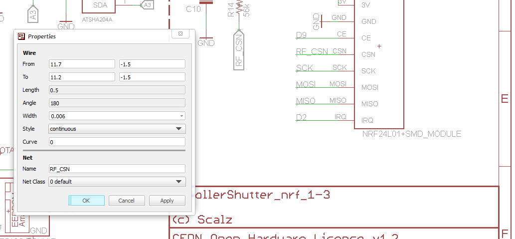
Hey Scalz, u have forgotten to connect the CSN - Pin in your PCB file for NRF24 ;-) I just solder a bridge between NRF Pin 4 and R14
-
Yah, i know, take it easy this is an minor bug :-)
Your misstake is in the schematic, your wire on the NRF24 CSN-PIN is unnamed.For feature Update, it is advisable to plug an ELKO ~400-500uF near the NRF24 Power, i have reciving problems whith "RF24_PA_HIGH" but i need hight for the distance.
-
But it was named! or the pullup resistor would not be wired, and it was also present on atmel.. and no airwire, weird!
well, i think it happened during converstion to nrf24.
Hopefully the pullup resistor is just near the radio!Is RF24_PA_HIGH available for nrf24 smd, i thought this was for High power nrf. i'm certainly wrong..I've no problem with rfm though.
I don't think i will do more, unfortunately, I mean in this case, it's sort of double job, and i'm using rfm69.
but when i can, i put rfm69 and nrf footprint (i have a pcb not released like this, not a shutter node).Now it's updated :) rev=1.3a for nrf
See you soon -
One question: what are your fuses settings for Optiboot? Dit u use the external 8MHz Clock?
Can you confirm:L: 0xEE
H: 0xDA
E: 0x06 -
But it was named! or the pullup resistor would not be wired, and it was also present on atmel.. and no airwire, weird!
well, i think it happened during converstion to nrf24.
Hopefully the pullup resistor is just near the radio!Is RF24_PA_HIGH available for nrf24 smd, i thought this was for High power nrf. i'm certainly wrong..I've no problem with rfm though.
I don't think i will do more, unfortunately, I mean in this case, it's sort of double job, and i'm using rfm69.
but when i can, i put rfm69 and nrf footprint (i have a pcb not released like this, not a shutter node).Now it's updated :) rev=1.3a for nrf
See you soon -
What the ??
Are you using Eagle 7x ?? I'm still using 6.5..when it works i don't change if no need ;)
but dooo! In my version i see the signal..i think this is sort of very exotic bug case and i got in my face lol
Weird, hein !
no matter thx for reporting, good to know i'll remember or update, we learn from our errors as we say :) -
easy to solve when you've eagle 7.5 ahah
For fuse&bootloader, you can use OTA howto, that's the same : https://www.mysensors.org/about/ota
-
easy to solve when you've eagle 7.5 ahah
For fuse&bootloader, you can use OTA howto, that's the same : https://www.mysensors.org/about/ota
@scalz Are you sure about the Fuses? 0xE2 is normal for int. clock?! Or i am wrong?
http://eleccelerator.com/fusecalc/fusecalc.php?chip=atmega328p&LOW=E2&HIGH=DA&EXTENDED=06&LOCKBIT=FF

Hello! It looks like you're interested in this conversation, but you don't have an account yet.
Getting fed up of having to scroll through the same posts each visit? When you register for an account, you'll always come back to exactly where you were before, and choose to be notified of new replies (either via email, or push notification). You'll also be able to save bookmarks and upvote posts to show your appreciation to other community members.
With your input, this post could be even better 💗
Register Login