💬 Roller Shutter Node


  • Hardware Contributor

    @GertSanders Any specific prt you're struggling with? I think i can see his routes and may be of some help until Scalz gets back to you.


  • Hardware Contributor

    @Samuel235

    I just realised: he is not using the two relays to give two AC sources, but uses them to switch a motor.

    I was still in my mind thinking about my relay board (not published) which gives a contact with 220V when relay is closed and is AC free when relay is open.

    But I will check his BOM to see which relays @scalz is using. They are smaller then the popular SONGLE relays and the pin layout is better for keeping AC away from low voltage circuitry.


  • Hardware Contributor

    @GertSanders Please inform me of those he uses when you find them. I too like the look of those on his board. Does your module use solid state relays?


  • Hardware Contributor

    hi guys 🙂

    @Tmaster thx I'm glad 😉 I'm not lucky this is so compact, so I couldn't have both footprint (rfm and nrf), argh so I made two rev. Don't ask me why, I still don't know, I'm going crazy 😆

    @GertSanders schematic is already there. arg, I thought it was enough readable. what do you want to know about AC?
    Here, for protecting shutter motor I had to put relays in serie.
    So there is one SPST NO for "power". When enabled, if I remember right, it moves UP. Send logic 1 to the 2nd relay, and as it is SPDT it will go DOWN. Disable the first one, no more juice...
    if motor is AC, the 12_220 pad need to be connected to one LIVE.
    if motor is DC, 12_220 need to be connected to your DC source.

    Relays I'm using are well known OMRON. G5Q. I choosed them exactly for what you said, size and footprint. Nice price at tme, I have a bunch of them 😉 No ad 🙂 I have other more powerful 16a too, for a special multi relays board...

    I have modified a little bit my thing. Boards are ordered. I will try to upload asap. I'm a bit busy and would like to check few things before, you know..Oh, and I have other cool projects ongoing, I hope you will like them 😉


  • Hardware Contributor

    @Samuel235
    My board is using the cheap Songle relays (5V switches 10A 220VAC).

    In the mean time I found out he is using G5Q by OMRON series. They have a Panasonic equivalent at Aliexpress, I will try those.


  • Hardware Contributor

    @scalz
    No worries about the schematic. I was just confused (but it is clear now). Do you have a link for the relays ? I can find equivalents from Panasonic on the Aliexpress site. Not sure what vendor you mean with TME (url?)

    I always look forward to your projects 🙂


  • Hardware Contributor

    @GertSanders I'm reassured 😉 I try to keep things understable but sometimes my brain is confused lol
    Relays I'm using:
    http://www.tme.eu/en/details/g5q-1-eu-5dc/miniature-electromagnetic-relays/omron/g5q-1-eu-5vdc/
    http://www.tme.eu/en/details/g5q-1a-eu-5dc/miniature-electromagnetic-relays/omron/g5q-1a-eu-5vdc/
    The cheaper I found at a trusted source. nice isn't it?


  • Hardware Contributor

    @GertSanders a last note..that's not my very last schematic rev. On this previous one, you can see I was protecting globally the board with a 5Amp fuse, good for relays here (shutter motor don't use so much), but what about hilink?? not rated for 5a at all! So on bottom, I have added a smd fuses for the hilink only. So there are two fuses on my board now.
    Link of the smd fuse :
    http://www.mouser.com/ds/2/9/MF2410 Datasheet2013-247737.pdf
    I never tried this one so I will tell you if it works well. I have 0.8 and 1amp ref. I think it's largely enough secure...varistor, temp sensor, two fuses...lol I don't know if there are so much things in commercial products..If there is a problem on the board, lot of chance there is a bigger problem somewhere else lol


  • Hardware Contributor

    Hey there 🙂

    sorry for delay, busy busy time..
    Just to say i have uploaded latest pics , and I will try to make a vid of the thing in action as soon as i can..
    See you soon!


  • Hardware Contributor

    hi

    my node is still working well..i'm trying to reorganize my priority, I'm enough confident to release 😊
    for the report, I don't remember if I explained how i did my acs calibration so..

    Here a pic of an homemade load, don't laugh, it can be useful 🙂

    0_1470429936597_load.JPG
    I can power 1 to 5 incandescent bulbs separately on a row, and there is also a switch to power completely the other row. So I was able to measure 0-1000W by 100W step. cool 🙂

    And the report after calibrating a bit opamp circuit

    0_1470430097752_acs_notes.png

    So you can see that's pretty nice.

    I know there could be some debate about the way I decided to do the endstop monitoring. I could have used other ways than acs sensors. but after footprint evaluation, cost, versatility etc..I preferred imho this way.
    Plus, like this, by using the opamp, I can have a nice curve for a 3V adc, keeping atmel 3v, and saving some uc cycle without doing sampling for 50hz etc...and I can use some fast adc for faster..


  • Hardware Contributor

    @scalz said:

    @tonnerre33 yep. you're right, it's cms I'm sorry 😞 I think.. good luck to fit everything with arduino mini in wall.
    About the cutoff, I replaced this by a simple temperature sensor for monitoring. imho, i have two fuses onboards + varistor, enough for me comparing to some commercial products. If it burns you have a big problem somewhere!! But sure it's better to know what you do, thermal fuses is good 😉

    About the cutoff, i understand you replaced this by a simple temperature sensor but do you cut the primary of the AC source if the temperature is too hight ?
    If we only cut the ouput relays and the problem came from the AC source, how we cut the power for stop the overheating ?

    Thx for your answers and thx for this project 😉


  • Hardware Contributor

    @tonnerre33 : and how do you protect your thermofuse? 😆 I'm joking 🙂 I think it's a bit redundant, protection on protection for this project, especially..
    But that's an interesting question, I will try to answer how I have made my choice, I hope to not miss a point, and don't forget it is imho 😉

    About the fuse:

    • if you look at the board (topview), you will see that's too tight to put the thermofuse. And I prefer AC isolated on pcb side. The previous rev of this board was few millimeters more wide, and didn't fit well first. Now it's better
    • how to secure, I thought? what if hilink fails (paranoid mode as it's a nice module)? So I decided to put a dedicated fast blow fuse for hilink. Right, no temperature! (Note : there is another 5amps fuses but it's for handling relays).
    • Two choice, heu no 3 in fact.
      I could use rfm to monitor hilink temp...could work, not the best precision, but that would need I put rfm69 under hilink to be precise enough as I want. Maybe paranoid on EMI etc..but I didn't wanted to put the radio under hilink, and for antenna performance.
      So..a CTN? I was using this on the previous rev, under hilink.
      For this one, I have decided to use onewire sensor glued on hilink side. nice too.

    But..you're still right, no temp cutoff! damn!! But:

    • why would the temperature increase??? over current somewhere? on a bad hilink or something else? etc..
      The hilink fuse should be already dead at this moment! If I remember well the ref I use is a 500mah, there is 1A variant too. For lightnings storm etc.. there is also a varistor.
    • and what happens if temp increase? For thermofuse, are you notified if it happens? or a bit before it happens? Or can you predict it for weeks? In my case, I like the idea to be able to monitor/detect weeks before, than waiting it burn in the wall! in case the board starts to heat more than usual,
    • the hilink is already well protected.
    • what else 😄 ah yes! I have millings on the boards, respected creepage/clearance..

    Now, I'm curious, I would like to know how can I make my board burning in the wall? I would like to try..I think my main electric system will trigger too..

    Very personal opinion, perhaps i've not answered completely to your question...but i've answered why I thought it was redundant 🙂


  • Hardware Contributor

    @Nca78 : I prefer to answer this here as the question was related to shutter

    @Nca78 said:

    @scalz on your board you use relays that are much bigger than those tiny SSRs, in the end it probably gives the same result for the space used on the board, and as you have the radio on the other side the depth difference is not very big, just 2mm from the plastic at the base of the connectors.

    The board you're talking on the other topic is different.For multiple reasons, that's not the best choice to use SSR for shutters. commercial products use spst+spdt too, I guess.
    For relays choice: with no snubber, 5amps will be less good than a 10amps.

    About footprint constraints, these two boards are not comparable.
    If it's for a shutter node, on mine there is a current sensor, relay driver, signing authentication chip, flash eeprom for memory etc..and I respect all clearance and creepage, no radio near AC nor other traces, all components on one side for maintenance..
    Like I said, I wish good luck to someone who want to make my board using arduino mini + hilink with all my requirements, same size and thickness. You can't do small tight things with big things or I want to see creepage/clearance results 😉


  • Hardware Contributor

    It's ok, i haven't seen the fuse in the primary of the hilink 😉
    with this fuse, the protection is guaranteed, then you don't need termofuse in this project 👍
    thanx for answer how you made your choice and i hope the release will arrive soon 🙂


  • Hardware Contributor

    @scalz I agree with you it's not the best choice, I just want to try it anyway and see how it behaves. The configuration you use is probably the one used in commercial products, but my neighbour has some electric shutters with fibaro modules and they are really tiny, I wonder what relays they use. They have an external antenna (a wire) so it probably eases the internal design, they use a transformerles design, but I still don't get how they can fit relays inside and respect clearance/creepage.

    I'm tempted with your board, but like many others the SMD components are putting me off at the moment. Wonder if this type of board would not be a good candidate for an ESP8266 module ?
    It would take space similar to a radio module, but without any routing needed to connect to atmega. (and the castellated pins are not very hard to solder :))


  • This post is deleted!

  • Hardware Contributor

    @Nca78 oki it's good to experiment by yourself you're right 🙂 and if you do something better, sure i would use it 😉 I'm not dumb!

    for esp8266, i thought about it too.
    First, I'm not a fan of wifi for rollershutter, it's like a door..I prefer something more secured with atmel/rfm/signing. But i have tried in eagle to see.
    footprint was not really better! just looking at the topview, it's difficult to make smaller..as you can see with @dpressle board, which is nice design though, but 5x5, not same features, and i don't know about thickness, antenna near traces etc..so not same goals as I said.

    for fibaro modules, I don't have one so i can't tell, I know they are good in miniaturization. but I'm pretty sure they are using transformless, with a very tight, controlled and professional design etc..but my design is opensource work (almost for the moment) with a current sensor which can add some versatility who knows.

    Maybe not so easy to handsolder for noobs, i can agree.
    I could have used 0603, instead i kept 0805. in case middle experienced people would build it with moderate tools. even a noob who want to learn and know a bit about AC. On my side, no glasses and i don't need a magnifier with 0805, nor 0603 but it's easier with one. Maybe lucky. Try maybe you don't need it too guys, with little patience, pratice and fun 🙂 I admit I'm not noob but I'm not former electronician.

    A trick: if not really friendly with smd, and need some boards, a stencil costs 15-20$, it's reusable, boost the job, and if you don't have reflow oven, there are multiple alternative like using your solder iron as solder paste is already applied, or hot gun etc.

    taste and colours sometimes... 🙂


  • Hardware Contributor

    @scalz - Where do you get your stencils from, everywhere that i have asked they are $60+


  • Hardware Contributor

    @Samuel235 Elecrow when i order pcb, or oshstencils.com is great too


  • Hardware Contributor

    Beautiful design @scalz ! (I've looked before, but closer this time.) Compact, neat, safe and many features. Another AC design reference to get some ideas and inspiration from. 😃


  • Hardware Contributor

    @scalz - Thank you! Finally an affordable stencil provider.


  • Hardware Contributor

    Hey guys 🙂

    this time is time for update 😉
    rfm69 version is uploaded. Added a bit of documentation. github in sync with this topic. gerbers and design files released too.
    Only STL and the sketch are missing, not for long, I have just finished to write and try formatting my post, upload and check everything etc.. Maybe there are some typos in doc I think etc..

    I am looking if it could be interesting to use PCBA through pcbway or others.
    At least, pcb should be available here through pcbway, I have pushed the button 🙂

    Enjoy ✌


  • Hardware Contributor

    Great, I would be interested in PCBA board as I'm not feeling motivated for playing with solder paste and buying a reflow oven yet 😉
    I'm more interested in a NRF24 version and if you can only get RFM69 version with PCBA then I will adapt, but maybe you can have an option without the radio ?
    At the moment I would order only 1-2 boards to make some intensive testing first, I have some big windows (over 2m*2m so it will need a relatively powerfull motor), and tropical weather with high temperature and high humidity.
    But if it survives the local conditions I have 9 manual roller shutters in my appartment and I know some neighbours are interested in home automation stuff also, with 350 appartments in my building there's some potential for orders 😄


  • Hardware Contributor

    @Nca78
    wow! cool.
    I hope it will fit your needs 😉

    For the nrf24 version, I just need to add few silkscreen, and it's ok to upload, it's the same version, only rerouted a bit differently at radio side.

    don't worry no need of a reflow oven, just a fine solder iron. but I agree, sometimes because I feel something easy I think it's easy for other..
    That's why I will ask pcbway for the PCBA and I will ask my regular fabhouse too.
    I am thinking :

    • only pcb
    • only smd parts soldered, up to us to source others component like relays, radio etc..
    • full assembled. curious to see the cost.

    On my side, I can do very small batch sometimes. like 10-20 boards. But I live in France, so, for far country it may be not interesting regarding shipping fees etc

    I'm also actually working on release for others boards..I need to sort all my stuff, to have more air for software and new hardware.. 🙂


  • Hardware Contributor

    @scalz in fact je suis Français 😉
    Do you think you can have one board ready in around a month time ? I'll have family coming from France at the end of september so I can give you an address in France where to send the board 🙂

    I'm pretty sure I'll be ok with smd after some time, but I'm just not ready yet. I have bought some kits to train before I try before I do it on real boards/components.


  • Hardware Contributor

    @Nca78 hehe. that's what I thought first time i saw your nick, don't tell me why maybe the 78 🙂 that's fun.

    I will see. this is nrf24 board you want, isn't it? I have no of these in stock but I have an order of multiple pcb to do this week. so I will buy a set. I will use DHL..not so patient when there are new boards to try 🙂 So I will tell you what I can do..


  • Hardware Contributor

    @scalz If you are not ready with the NRF24 version I will be fine with a RFM version, I'll just build a RFM gateway it's not a big deal, and I'll have no excuse not to try all those nice boards with RFM69 that are on openhardware 😉


  • Hardware Contributor

    nrf24 smd version is uploaded. Have fun


  • @scalz I'm another one from France and very interessing in pcba version with rfm69 cause sma is not my cut of tea :).
    Anyway thank for your work and ideas,


  • Hardware Contributor

    @fets cool. About PCBA, for the moment; it's on fabhouse hand, I'm waiting for the quotation, and if everything goes well, this board may become a part of Mysensors project, meaning supporting Mysensors, I'm very glad 🙂


  • @Scalz : Hello, what a great job ! it's exactly the thing i'm trying to do since few months. But severe issues with relay and my 220v rolling shutters. Actually, the relays freeze sometimes and stay glue to a position. I read a lot about the inductive load and snubber, but i'm a newbie with electronics. I tried differents relays : from blue one classic to APF30205, but always fails.
    Did you encounter problem with your OMRON G5Q ? Is the varistor the solution or it's only for other purpose (security,...). Here is my project https://github.com/coxifred/PimpMyCeliane/wiki
    Thanks for you response, and congratulations (twice).


  • Hardware Contributor

    @coxifred
    Hello. sorry for delay..busy time..
    I already did my design when I saw your build. But I preferred to not use wifi for rollershutter..

    If you're newbie in electronics, be careful with AC and your motors 😉

    • I don't see any safety on your build..
    • seems your relays are in //, so not interlocked. Better in serie, so you can't do UP & DOWN at same time. Not a problem in software, but if parasitic problems, then it could happen.

    I have no problem with my relays but I have only tried on a somfy motor, and another old blind motor.

    Relay can stay glued because of multiple reasons, not easy to debug at distance 😉

    • EMI parasites etc... esp8266, especially nodemcu module could be sensitive. And lot of wire etc near AC lines etc is a nasty combo. this would not pass EMI tests!
    • So, at relay input : EMI for instance or, I don't know if your relay module has this, but that's better to use relay driver or at least some diode. . It can avoid improves false things on relay input.
    • If you're sure you have no problem on relay driver/transistor side, then it can be at output. It can be stayed glue in inductive overload for instance. If bad quality relay. If relay is good quality. Perhaps you need an additional snubber. Which is why I have oversized my relays (10Amp).

    Maybe I have missed few others points, but I hope that will help you 🙂


  • @scalz : Thanks for your response. For me all eletronic/software before output is ok. I tried with simple bulbs, works every time, no glue. The problem appears only with rolling shutter motors (wich are not somfy, but 220v). I think i need a snubber (for inductive overload ) but don't know how to wire it at the output, and wich model. I'll buy your relay model and test again. Perhaps i was not lucky with my relay. I even buyed a Chacon/DIO (433) rolling shutter module to see what kind of relay are they using. I have to take a voltage measure on the (chacon) input's relay, not node, too much time:)
    Thanks 4 your response.


  • Hardware Contributor

    Hello,

    The PCB order link is for nrf24 or RFM69 version ?

    Edit :

    omg, i see the answer in the first page ^^ it's for RFM69 version .

    When will you give the link for order PCB with nrf 24 ?


  • Hardware Contributor

    Hello,

    Where can we found the program (.ino) for this board ?

    Thx


  • Hardware Contributor

    Where can i find the example sketch?


  • There is no official sketch avaiable at this moment. And @scalz is working hard on RFM69 ... I began yesterday to write a new sketch, I will publish in few days (weeks ?).


  • Hardware Contributor

    Why do you want an example sketch ?
    hmm..my precious sketch 😛
    @Fabien is right that's quite busy days 🙂
    I didn't published it yet because i prefer release when it's polished as i like..
    Well, as Fabien is a betatester 😉
    i've published a pre beta version! on my git https://github.com/scalz/MySensors-HW/tree/development/RollerShutterNode/FW/MyRollershutter

    BUT i'm actually busy so i won't have time for support on setup. i think it's enough documented for the moment.
    I prefer to tell this than giving hope..better like this. I learnt this from a smart guy recently 🙏

    That said i hope you will have fun! and i will try to update as i can..you've not seen the new version of this board 😋


  • Hardware Contributor

    Hey, no Problem 🙂

    I just ask for it, as you write it is in the examples folder 😉

    Thanks for the pre Beta, i will work on it 👍


  • Hardware Contributor

    @scalz Thanks for the pre beta sketch.
    i have searched the sketch many times in the example folder too 🙂 But no examples folder find 😉
    I have posted some pictures of the pcb here i fyou want to see:

    http://www.photorapide.com/albums/jordan/khjept/circuit-pcb-roller-shutter-node.html


  • Hardware Contributor

    Hey Scalz, u have forgotten to connect the CSN - Pin in your PCB file for NRF24 😉 I just solder a bridge between NRF Pin 4 and R14


  • Hardware Contributor

    @takero
    thx for reporting!
    i'm using rfm69, argh. i will take a look asap.


  • Hardware Contributor

    Yah, i know, take it easy this is an minor bug 🙂
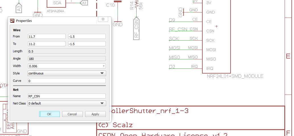
    Your misstake is in the schematic, your wire on the NRF24 CSN-PIN is unnamed.

    For feature Update, it is advisable to plug an ELKO ~400-500uF near the NRF24 Power, i have reciving problems whith "RF24_PA_HIGH" but i need hight for the distance.


  • Hardware Contributor

    @Takero

    But it was named! or the pullup resistor would not be wired, and it was also present on atmel.. and no airwire, weird!
    well, i think it happened during converstion to nrf24.
    Hopefully the pullup resistor is just near the radio!

    Is RF24_PA_HIGH available for nrf24 smd, i thought this was for High power nrf. i'm certainly wrong..I've no problem with rfm though.

    I don't think i will do more, unfortunately, I mean in this case, it's sort of double job, and i'm using rfm69.
    but when i can, i put rfm69 and nrf footprint (i have a pcb not released like this, not a shutter node).

    Now it's updated 🙂 rev=1.3a for nrf
    See you soon


  • Hardware Contributor

    One question: what are your fuses settings for Optiboot? Dit u use the external 8MHz Clock?
    Can you confirm:

    L: 0xEE
    H: 0xDA
    E: 0x06


  • Hardware Contributor

    @scalz Yes, the resistor is very close 🙂

    In my .sch the wire is not named 😉 But anyway it works 👍

    alt text


  • Hardware Contributor

    @Takero

    What the ??
    Are you using Eagle 7x ?? I'm still using 6.5..when it works i don't change if no need 😉
    but dooo! In my version i see the signal..i think this is sort of very exotic bug case and i got in my face lol
    0_1476951269074_2016-10-20_10-13-29.jpg
    Weird, hein !
    no matter thx for reporting, good to know i'll remember or update, we learn from our errors as we say 🙂


  • Hardware Contributor

    @scalz
    Yes 7.5. Hey it was an "easy to solve" problem 😄

    . . . maybe an eagle bug


  • Hardware Contributor

    easy to solve when you've eagle 7.5 ahah

    For fuse&bootloader, you can use OTA howto, that's the same : https://www.mysensors.org/about/ota


  • Hardware Contributor

    @scalz Are you sure about the Fuses? 0xE2 is normal for int. clock?! Or i am wrong?

    http://eleccelerator.com/fusecalc/fusecalc.php?chip=atmega328p&LOW=E2&HIGH=DA&EXTENDED=06&LOCKBIT=FF


  • Hardware Contributor

    yes this ok, i'm using this for most of my nodes.
    And your link shows that it sets internal rc.


  • Hardware Contributor

    Ok, Thanks


  • Hardware Contributor

    Hey Scalz,

    my prototype of your RollerShutter works well right now. I have add an Capacitor (470uF) near the NRF (it is realy needed! otherwise OTA CRC Fail, lost packages)

    I have a litte bit trouble with the Current Sensor or the calculation of this.
    I Used 2 60W Bulbs, if i PressDown or UP the Power Value increase up to 350W and need a loooooooonng time to decrease. round about 1W per sec.

    Is this normal? In my opinion not but maybe my ASC is defective? I use a modification of your pre-alpha Sketch


  • Hardware Contributor

    hmm. i didn't have 1w/sec.. perhaps acs.. i've already got a few defective. i'll check a bit when i'll have more time, too much cooking.
    In case you can set default define duration, and this works well then.
    But looks you got it! Great to hear it though 🙂


  • Hardware Contributor

    Yaah dont hurry 😄

    here is the log:

     [2016-11-01 10:49:04.702 Info] RX	0;255;3;0;9;TSP:MSG:READ 50-50-0 s=6,c=1,t=17,pt=3,l=2,sg=0:465
     [2016-11-01 10:49:04.727 Info] RX	50;6;1;0;17;465
     [2016-11-01 10:49:04.728 Info] RX	0;255;3;0;9;TSP:MSG:READ 50-50-0 s=6,c=1,t=17,pt=3,l=2,sg=0:466
     [2016-11-01 10:49:04.728 Info] RX	50;6;1;0;17;466
     [2016-11-01 10:49:14.731 Info] RX	0;255;3;0;9;TSP:SANCHK:OK
     [2016-11-01 10:49:28.130 Info] RX	0;255;3;0;9;TSP:MSG:READ 50-50-0 s=6,c=1,t=17,pt=3,l=2,sg=0:445
     [2016-11-01 10:49:28.137 Info] RX	50;6;1;0;17;445
     [2016-11-01 10:49:28.265 Info] RX	0;255;3;0;9;TSP:MSG:READ 50-50-0 s=6,c=1,t=17,pt=3,l=2,sg=0:446
     [2016-11-01 10:49:28.267 Info] RX	50;6;1;0;17;446
     [2016-11-01 10:49:54.722 Info] RX	0;255;3;0;9;TSP:MSG:READ 50-50-0 s=6,c=1,t=17,pt=3,l=2,sg=0:425
     [2016-11-01 10:49:54.727 Info] RX	50;6;1;0;17;425
     [2016-11-01 10:49:54.787 Info] RX	0;255;3;0;9;TSP:MSG:READ 50-50-0 s=6,c=1,t=17,pt=3,l=2,sg=0:426
     [2016-11-01 10:49:54.788 Info] RX	50;6;1;0;17;426
     [2016-11-01 10:50:14.760 Info] RX	0;255;3;0;9;TSP:SANCHK:OK
     [2016-11-01 10:50:23.029 Info] RX	0;255;3;0;9;TSP:MSG:READ 50-50-0 s=6,c=1,t=17,pt=3,l=2,sg=0:405
     [2016-11-01 10:50:23.032 Info] RX	50;6;1;0;17;405
     [2016-11-01 10:50:23.054 Info] RX	0;255;3;0;9;TSP:MSG:READ 50-50-0 s=6,c=1,t=17,pt=3,l=2,sg=0:406
     [2016-11-01 10:50:23.055 Info] RX	50;6;1;0;17;406
     [2016-11-01 10:50:53.223 Info] RX	0;255;3;0;9;TSP:MSG:READ 50-50-0 s=6,c=1,t=17,pt=3,l=2,sg=0:385
     [2016-11-01 10:50:53.226 Info] RX	50;6;1;0;17;385
     [2016-11-01 10:50:53.261 Info] RX	0;255;3;0;9;TSP:MSG:READ 50-50-0 s=6,c=1,t=17,pt=3,l=2,sg=0:386
     [2016-11-01 10:50:53.262 Info] RX	50;6;1;0;17;386
     [2016-11-01 10:51:14.788 Info] RX	0;255;3;0;9;TSP:SANCHK:OK
     [2016-11-01 10:51:25.712 Info] RX	0;255;3;0;9;TSP:MSG:READ 50-50-0 s=6,c=1,t=17,pt=3,l=2,sg=0:365
     [2016-11-01 10:51:25.718 Info] RX	50;6;1;0;17;365
     [2016-11-01 10:51:25.725 Info] RX	0;255;3;0;9;TSP:MSG:READ 50-50-0 s=6,c=1,t=17,pt=3,l=2,sg=0:366
     [2016-11-01 10:51:25.732 Info] RX	50;6;1;0;17;366
     [2016-11-01 10:51:59.985 Info] RX	0;255;3;0;9;TSP:MSG:READ 50-50-0 s=6,c=1,t=17,pt=3,l=2,sg=0:345
     [2016-11-01 10:51:59.989 Info] RX	50;6;1;0;17;345
     [2016-11-01 10:52:00.013 Info] RX	0;255;3;0;9;TSP:MSG:READ 50-50-0 s=6,c=1,t=17,pt=3,l=2,sg=0:346
     [2016-11-01 10:52:00.014 Info] RX	50;6;1;0;17;346
     [2016-11-01 10:52:14.818 Info] RX	0;255;3;0;9;TSP:SANCHK:OK
     [2016-11-01 10:52:36.088 Info] RX	0;255;3;0;9;TSP:MSG:READ 50-50-0 s=6,c=1,t=17,pt=3,l=2,sg=0:325
     [2016-11-01 10:52:36.091 Info] RX	50;6;1;0;17;325
     [2016-11-01 10:52:36.117 Info] RX	0;255;3;0;9;TSP:MSG:READ 50-50-0 s=6,c=1,t=17,pt=3,l=2,sg=0:326
     [2016-11-01 10:52:36.119 Info] RX	50;6;1;0;17;326
     [2016-11-01 10:53:14.248 Info] RX	0;255;3;0;9;TSP:MSG:READ 50-50-0 s=6,c=1,t=17,pt=3,l=2,sg=0:305
     [2016-11-01 10:53:14.251 Info] RX	50;6;1;0;17;305
     [2016-11-01 10:53:14.278 Info] RX	0;255;3;0;9;TSP:MSG:READ 50-50-0 s=6,c=1,t=17,pt=3,l=2,sg=0:306
     [2016-11-01 10:53:14.279 Info] RX	50;6;1;0;17;306
     [2016-11-01 10:53:14.848 Info] RX	0;255;3;0;9;TSP:SANCHK:OK
     [2016-11-01 10:53:54.586 Info] RX	0;255;3;0;9;TSP:MSG:READ 50-50-0 s=6,c=1,t=17,pt=3,l=2,sg=0:285
     [2016-11-01 10:53:54.590 Info] RX	50;6;1;0;17;285
     [2016-11-01 10:53:54.613 Info] RX	0;255;3;0;9;TSP:MSG:READ 50-50-0 s=6,c=1,t=17,pt=3,l=2,sg=0:286
     [2016-11-01 10:53:54.614 Info] RX	50;6;1;0;17;286
     [2016-11-01 10:54:14.876 Info] RX	0;255;3;0;9;TSP:SANCHK:OK
     [2016-11-01 10:54:36.813 Info] RX	0;255;3;0;9;TSP:MSG:READ 50-50-0 s=6,c=1,t=17,pt=3,l=2,sg=0:265
     [2016-11-01 10:54:36.817 Info] RX	50;6;1;0;17;265
     [2016-11-01 10:54:36.843 Info] RX	0;255;3;0;9;TSP:MSG:READ 50-50-0 s=6,c=1,t=17,pt=3,l=2,sg=0:266
     [2016-11-01 10:54:36.845 Info] RX	50;6;1;0;17;266
     [2016-11-01 10:55:14.904 Info] RX	0;255;3;0;9;TSP:SANCHK:OK
     [2016-11-01 10:55:21.198 Info] RX	0;255;3;0;9;TSP:MSG:READ 50-50-0 s=6,c=1,t=17,pt=3,l=2,sg=0:245
     [2016-11-01 10:55:21.202 Info] RX	50;6;1;0;17;245
     [2016-11-01 10:55:21.223 Info] RX	0;255;3;0;9;TSP:MSG:READ 50-50-0 s=6,c=1,t=17,pt=3,l=2,sg=0:246
     [2016-11-01 10:55:21.224 Info] RX	50;6;1;0;17;246
     [2016-11-01 10:56:08.275 Info] RX	0;255;3;0;9;TSP:MSG:READ 50-50-0 s=6,c=1,t=17,pt=3,l=2,sg=0:225
     [2016-11-01 10:56:08.278 Info] RX	50;6;1;0;17;225
     [2016-11-01 10:56:08.304 Info] RX	0;255;3;0;9;TSP:MSG:READ 50-50-0 s=6,c=1,t=17,pt=3,l=2,sg=0:226
     [2016-11-01 10:56:08.306 Info] RX	50;6;1;0;17;226
     [2016-11-01 10:56:14.934 Info] RX	0;255;3;0;9;TSP:SANCHK:OK
     [2016-11-01 10:56:58.403 Info] RX	0;255;3;0;9;TSP:MSG:READ 50-50-0 s=6,c=1,t=17,pt=3,l=2,sg=0:205
     [2016-11-01 10:56:58.406 Info] RX	50;6;1;0;17;205
     [2016-11-01 10:56:58.432 Info] RX	0;255;3;0;9;TSP:MSG:READ 50-50-0 s=6,c=1,t=17,pt=3,l=2,sg=0:206
     [2016-11-01 10:56:58.434 Info] RX	50;6;1;0;17;206
     [2016-11-01 10:57:14.963 Info] RX	0;255;3;0;9;TSP:SANCHK:OK
     [2016-11-01 10:57:51.378 Info] RX	0;255;3;0;9;TSP:MSG:READ 50-50-0 s=6,c=1,t=17,pt=3,l=2,sg=0:185
     [2016-11-01 10:57:51.381 Info] RX	50;6;1;0;17;185
     [2016-11-01 10:57:51.403 Info] RX	0;255;3;0;9;TSP:MSG:READ 50-50-0 s=6,c=1,t=17,pt=3,l=2,sg=0:186
     [2016-11-01 10:57:51.404 Info] RX	50;6;1;0;17;186
     [2016-11-01 10:58:14.991 Info] RX	0;255;3;0;9;TSP:SANCHK:OK
     [2016-11-01 10:58:47.254 Info] RX	0;255;3;0;9;TSP:MSG:READ 50-50-0 s=6,c=1,t=17,pt=3,l=2,sg=0:165
     [2016-11-01 10:58:47.280 Info] RX	50;6;1;0;17;165
     [2016-11-01 10:58:47.281 Info] RX	0;255;3;0;9;TSP:MSG:READ 50-50-0 s=6,c=1,t=17,pt=3,l=2,sg=0:166
     [2016-11-01 10:58:47.282 Info] RX	50;6;1;0;17;166
     [2016-11-01 10:59:15.019 Info] RX	0;255;3;0;9;TSP:SANCHK:OK
     [2016-11-01 10:59:46.972 Info] RX	0;255;3;0;9;TSP:MSG:READ 50-50-0 s=6,c=1,t=17,pt=3,l=2,sg=0:145
     [2016-11-01 10:59:46.977 Info] RX	50;6;1;0;17;145
     [2016-11-01 10:59:47.040 Info] RX	0;255;3;0;9;TSP:MSG:READ 50-50-0 s=6,c=1,t=17,pt=3,l=2,sg=0:146
     [2016-11-01 10:59:47.041 Info] RX	50;6;1;0;17;146
     [2016-11-01 11:00:15.047 Info] RX	0;255;3;0;9;TSP:SANCHK:OK
     [2016-11-01 11:00:52.176 Info] RX	0;255;3;0;9;TSP:MSG:READ 50-50-0 s=6,c=1,t=17,pt=3,l=2,sg=0:125
     [2016-11-01 11:00:52.181 Info] RX	50;6;1;0;17;125
     [2016-11-01 11:00:52.244 Info] RX	0;255;3;0;9;TSP:MSG:READ 50-50-0 s=6,c=1,t=17,pt=3,l=2,sg=0:126
     [2016-11-01 11:00:52.245 Info] RX	50;6;1;0;17;126
     [2016-11-01 11:01:15.076 Info] RX	0;255;3;0;9;TSP:SANCHK:OK
     [2016-11-01 11:02:08.445 Info] RX	0;255;3;0;9;TSP:MSG:READ 50-50-0 s=6,c=1,t=17,pt=3,l=2,sg=0:105
     [2016-11-01 11:02:08.449 Info] RX	50;6;1;0;17;105
     [2016-11-01 11:02:08.505 Info] RX	0;255;3;0;9;TSP:MSG:READ 50-50-0 s=6,c=1,t=17,pt=3,l=2,sg=0:106
     [2016-11-01 11:02:08.506 Info] RX	50;6;1;0;17;106
    

    Bootup Log:

    57	01.11.2016 12:34:04	TX	50	50		0	6	C_SET	V_WATT	UINT16	2	NO		62
    59	01.11.2016 12:34:05	TX	50	50		0	6	C_SET	V_WATT	UINT16	2	NO		63
    61	01.11.2016 12:34:05	TX	50	50		0	6	C_SET	V_WATT	UINT16	2	NO		64
    63	01.11.2016 12:34:06	TX	50	50		0	6	C_SET	V_WATT	UINT16	2	NO		65
    65	01.11.2016 12:34:07	TX	50	50		0	6	C_SET	V_WATT	UINT16	2	NO		66
    67	01.11.2016 12:34:08	TX	50	50		0	3	C_SET	V_TEMP	BYTE	1	NO		25
    69	01.11.2016 12:34:08	TX	0	0	50	50	3	C_SET	V_TEMP	BYTE	1	NO	ok	25
    71	01.11.2016 12:34:08	TX	50	50		0	6	C_SET	V_WATT	UINT16	2	NO		67
    73	01.11.2016 12:34:09	TX	50	50		0	6	C_SET	V_WATT	UINT16	2	NO		68
    75	01.11.2016 12:34:10	TX	50	50		0	6	C_SET	V_WATT	UINT16	2	NO		69
    77	01.11.2016 12:34:11	TX	50	50		0	6	C_SET	V_WATT	UINT16	2	NO		70
    79	01.11.2016 12:34:12	TX	50	50		0	6	C_SET	V_WATT	UINT16	2	NO		71
    81	01.11.2016 12:34:14	TX	50	50		0	6	C_SET	V_WATT	UINT16	2	NO		72
    83	01.11.2016 12:34:15	TX	50	50		0	6	C_SET	V_WATT	UINT16	2	NO		73
    85	01.11.2016 12:34:17	TX	50	50		0	6	C_SET	V_WATT	UINT16	2	NO		74
    87	01.11.2016 12:34:19	TX	50	50		0	6	C_SET	V_WATT	UINT16	2	NO		75
    89	01.11.2016 12:34:21	TX	50	50		0	6	C_SET	V_WATT	UINT16	2	NO		76
    91	01.11.2016 12:34:24	TX	50	50		0	6	C_SET	V_WATT	UINT16	2	NO		77
    93	01.11.2016 12:34:26	TX	50	50		0	6	C_SET	V_WATT	UINT16	2	NO		78
    95	01.11.2016 12:34:30	TX	50	50		0	6	C_SET	V_WATT	UINT16	2	NO		79
    97	01.11.2016 12:34:33	TX	50	50		0	6	C_SET	V_WATT	UINT16	2	NO		80
    99	01.11.2016 12:34:38	TX	50	50		0	6	C_SET	V_WATT	UINT16	2	NO		81
    101	01.11.2016 12:34:43	TX	50	50		0	6	C_SET	V_WATT	UINT16	2	NO		82
    103	01.11.2016 12:34:50	TX	50	50		0	6	C_SET	V_WATT	UINT16	2	NO		83
    106	01.11.2016 12:34:59	TX	50	50		0	6	C_SET	V_WATT	UINT16	2	NO		84
    108	01.11.2016 12:35:10	TX	50	50		0	6	C_SET	V_WATT	UINT16	2	NO		85
    110	01.11.2016 12:35:23	TX	50	50		0	6	C_SET	V_WATT	UINT16	2	NO		86


  • Hardware Contributor

    It is possible that you dont use the asc for the autocalibration yet? I cant find it in your Code .... I found only the read process.

    Corect me if i am wrong. 🙂


  • Hardware Contributor

    acs read can set an endstop bool = "event" which trig the shutter state machine. you should see it 😉
    in case you have some trouble, then you can set few default define in sketch to set your travel time. perhaps a cleareeprom needed, then shutter should be ready.


  • Hardware Contributor

    @scalz

    Yes, i work on it . . . still my ACS wont work well. At the moment i init the node with the Endstop Bool, that works fine.

    I work also on an delay between the UP/DOWN States, i don't like it if the shutter change the direktion directly. But . . . not find the right way yet 🙂

    EDIT: ACS works right now!!! 👍 I think my IC was defective 👎


  • Hardware Contributor

    Dont know why but while autocali. they stop messurement of current . . .

    If i start the process the first is go UP, my messurment of power is: 30W
    if i Power of the attached Bulb the value stays on 30W, so it is normal he cant detect anythink

    In your loop:

     // Read current sensor, endstop
      uint16_t acsread = 0;  
      acsread = readAdcWithFilter(ACS712_SENSOR, PS_64); 
      if (acsread < ACS712_LEVELDETECT) {
          // Endstop detected  
          if (getCalibrationState() > 0) setEndStopState(true); 
          else {};
      }
    

    I modified for debug like this:

    // Read current sensor, endstop
      uint16_t acsread = 0;  
      acsread = readAdcWithFilter(ACS712_SENSOR, PS_64); 
    
    
      Serial.print(F("ACS712: READ DEBUG: ")); 
      Serial.println(acsread);
    
    
      if (acsread < ACS712_LEVELDETECT) {
          // Endstop detected  
          if (getCalibrationState() > 0) setEndStopState(true); 
          else {};
      }
    

    It never change the value of acsread after the init process is started. . .

    LOG:

    TSP:MSG:READ 0-0-50 s=2,c=1,t=2,pt=0,l=1,sg=1:1
    CMD: Autocalibration
    ACS712: READ DEBUG: 7
    ACS712: READ DEBUG: 29
    ACS712: READ: 29
    TSP:MSG:SEND 50-50-0-0 s=6,c=1,t=17,pt=3,l=2,sg=0,ft=0,st=ok:29
    ACS712: READ DEBUG: 29
    ACS712: READ DEBUG: 29
    ACS712: READ DEBUG: 29
    ACS712: READ DEBUG: 29
    ACS712: READ DEBUG: 29
    ACS712: READ DEBUG: 29
    ACS712: READ DEBUG: 29
    ACS712: READ DEBUG: 29
    ACS712: READ DEBUG: 29
    ACS712: READ DEBUG: 29
    ACS712: READ DEBUG: 29
    ACS712: READ DEBUG: 29
    ACS712: READ DEBUG: 29
    ACS712: READ DEBUG: 29
    ACS712: READ DEBUG: 29
    ACS712: READ DEBUG: 29
    ACS712: READ DEBUG: 29
    ACS712: READ DEBUG: 29
    ACS712: READ DEBUG: 29
    ACS712: READ DEBUG: 29
    ACS712: READ DEBUG: 29
    ACS712: READ DEBUG: 29
    ACS712: READ DEBUG: 29
    ACS712: READ DEBUG: 29
    ACS712: READ DEBUG: 29
    ACS712: READ DEBUG: 29
    ACS712: READ DEBUG: 29
    ACS712: READ DEBUG: 29
    ACS712: READ DEBUG: 29
    ACS712: READ DEBUG: 29
    ACS712: READ DEBUG: 29
    

    29 will stay until timout stop. . . between this i power of the attached test bulb (20W)


  • Hardware Contributor

    Level detection work right now . . .

    my modifications:

    // send % progression for controller widgets NOT TESTED  
      static uint8_t oldpos = getPosition();
      
      if (oldpos != getPosition() && getCalibrationState()==0) {
        send(msgShutterPosition.set(getPosition()));
        send(msgPercent.set(getPosition()));
        oldpos = getPosition();
      } 
    

  • Hardware Contributor

    I am finished and everythink is working well right now.

    I dit some modifications on PCB:

    • add an 470uF near to NRF24
    • add two Diodes recovery diode (or free-wheeling diode) dunno how it called in english 🙂 at the relays

    And some changes in your example code 👍

    Thanks for the Layout, thanks for the code, thanks for help!

    I design a 3D Case, but only the bottom side. . . but not tested right now . .

    alt text

    0_1478263225360_RollerShutter_back.stl
    0_1478263256093_RollerShutter_Back.123dx


  • Did you try ACS measurement for up AND down ? On my 2 boards, i have problem with relay just over ACS and errors in current measurment (magnetic field of relay just over Hall sensor)
    @scalz : I think we could try to turn 90° acs712, it could be fine.


  • Hardware Contributor

    With a Little Bit Trouble yes. The Problem is the Dimension of the amplifier. Below 60W the messured voltage is to Low.

    I think it is netter the Diode must be in the Feedback cycle of the amplifier. But in my case the Free running voltage is below 6 and with running Roller above 20. So it is possible to detect the End stops. Just modify the variables.

    I will Test it in the"real" System tomorow. If it Works i will post the Sketch.


  • Hardware Contributor

    @Fabien
    i will take a look asap.. i'm actually playing with my nano32, and some design 😉
    perhaps for the atsam version when more time to release..

    @Takero
    thx for feedback 👍

    • i'll look to your suggestions too. for the wheeling diode if i remember it's integrated in the relay driver. depends what you mean.
    • For sketch, hehe, i warned it was not complete 🙂 but the most important there. I'll look at your change and update it, sure !i have actually no time to play with it, still using an old sketch.

    too much coding to do, and hardware to play! but this is so fun 🙂

    see you soon


  • Hardware Contributor

    @scalz said:

    for the wheeling diode if i remember it's integrated in the relay driver. depends what you mean

    It isn't 🙂


  • Hardware Contributor

    well, it is a zener, not wheeling diode, which should be enough..
    http://www.onsemi.com/pub_link/Collateral/MDC3105-D.PDF
    perhaps not for nrf! cool if it improves.

    sidenote: i won't change nrf version in future. as i only have rfm69 (doing nrf was bonus), i don't want to waste my time improving both! and i have enough pcb ahah


  • Hardware Contributor

    Dont Care 🙂 its cool. Zenner its not enoth but dont worry. I need it .. the nrf is verry "female" 😄 (sensible). But i think for both version, you have to modify the current messurment. No Roller shutter has >200w so u are on the Limit below 100w of adc scale.

    But hey it Works and your Layout is verry cool and Safe.


  • Very stange. Zener in forward side is equivalent to classical diode.
    @Takero, you change the amplifier ? Wich mods did you make ?


  • Hardware Contributor

    I was a little bit bussy the last days.
    My Nodes are completed installed right now, it works well. BUT, i had to change some thinks.

    I had the Probleme of automatic reset of the device if i set the shutter to 50% or anythink else 0% or 100%.
    The Diode alone dont solve these Probleme. I think the Problem is to stop the shutter while running. If i set it to 100% or 0% the shutter shut of before the relay falls down.

    I solve the Problem with a 220uF Capacitor at the 3.3V Out and deactivate the BOD.

    My Fuses right now: L: CF // H:DA // E:07

    Now it works very well!!

    @Fabien: I dont change the amp . . i just tested some thinks but it wont work . . for i dont use the current messurment and setup the Node with the manual endstop. It works realy good!

    Finaly again, Thanks @scalz

    The Temp. of the devices is below 30°C 😉

    In the picture the green temp.

    0_1481916187089_Unbenannt.JPG


  • Hi
    I was wondering if the ACS712 can detect the current if the roller shutter power is 85W?


  • Hi, there is something similar available although without an ac712. So you can't check the percentage o the shutter.
    See https://github.com/JanGoe/esp8266-wifi-relay
    I had one at home and it is working well. Because of the esp8266 it is directly connected to any controller using udp or MQTT or other protocols.
    The only problem is the missing box. I have to admit I wouldn't put this in my wall without a proper box using AC 240 V!!!
    The project you proposed is of course the most advanced. Do you think there is a smaller version available perhaps less parts on the BOM and easy to build?
    Thank you very much, kduino


  • Cloudy/rainning day ... Good for MySensors
    0_1491138689145_IMG_20170402_145718.jpg


  • There is a mistake on the above photo. Radios are on the wrong way (180°)


  • @scalz, little mistake on BOM, C4 is 100n AND 10n ..


  • Hi, I make this project, pretty cool.

    How I can upload the firmware? What I need to do?


  • Hardware Contributor

    @Sergio-Rodrigues
    It's better to talk about this here instead of private, so other people can learn or help you 😉

    it's "like" programming an arduino board.

    1. in arduino ide, program bootloader (for these, i used the sensebender board in Board manager).
    2. Then, with a FTDI adapter, program the rollershutter sketch.

    For more infos on programming arduino:

    What do you need to know exactly ??


  • Finnaly I find a solution with a very good WAF !
    I want to keep a sort of manual command (not gateway or controller dependant) and I don't want an expensive solution (my ODACE schneider button are quite expensive and I don't want to buy other button).
    But these button measure 38mm depth and @scalz board is about 20mm. My wall boxes are 50mm !
    Si I find some special wall boxes with an enclosure for home automation module. It's cheap (about 3€) and very well designed (french RT2012 compliant). I update the sketch with MY_TRANSPORT_WAIT_READY_MS so node can work alone. And I update sketch to work with bistable button. Works well on 2 windows since yesterday.
    Here is a photo before :
    0_1505166550880_IMG_20170911_233746.jpg


  • Admin

    Almost looks like this type type of part-rubber box that can be mounted without tearing down the wall:
    0_1505167914932_1426270.jpg

    https://www.eldirekt.se/elmaterial/elinstallation/infallda-dosor/multidosa-big-box

    SE - Multidosa – 00:35
    — Gycom


  • Some other photos (sorry, first one is not in the same room) :
    0_1505251878615_IMG_20170912_174015.jpg
    0_1505251889179_IMG_20170912_110933.jpg
    0_1505251895779_IMG_20170912_111143.jpg
    0_1505251903528_IMG_20170912_111331.jpg


  • One test screenshot (not definitive) of my habpanel (openHab 2.0 part).
    I'm using OpenHAB mysensors binding (from @TimO), node-red for rules, habpanel for UI, Tasker on android (for example open all RollerShuter just after morning alarm !).
    I can access OpenHAB via nginx reverse proxy with https and on my LAN, home automation have a separate VLAN (for security reasons). Thanks a lot to @scalz for this module.
    0_1505252614465_Capture du 2017-09-12 23-36-35.png


  • Hardware Contributor

    @scalz great work, sorry to dig up the topic, but good topics never die ( 🙂 ). Can you clarify some questions?

    • Way did you used 2 different relays? Way not only one type?
    • What is the Amp consumption of your motors? I know that 10A is overkill, but just to get one idea. Would 2A do it? (at 220V)
    • I see that you added a 8Mhz Cristal, way not use the internal clock? It's 8Mhz
    • I see that you use a relay driver, correct me if I'm wrong, that is because the rated coil consumption to those relays is 80mA.

    Thank You
    Great Work


  • @Soloam
    2 relay for interlocking system and add more security.
    I never mesure my current but it's low ... not 10A !
    Internal clock is not very precise and can vary with external parameters like temperature. And for this project it's better to have good precision.
    It's always better to use relay driver and not directly arduino pin.


  • Hardware Contributor

    @fabien said in 💬 Roller Shutter Node:

    @Soloam
    2 relay for interlocking system and add more security.
    I never mesure my current but it's low ... not 10A !
    Internal clock is not very precise and can vary with external parameters like temperature. And for this project it's better to have good precision.
    It's always better to use relay driver and not directly arduino pin.

    Thank you @Fabien all very clarifying, only one thing that I don't understand (sorry, but I like to use this projects to learn and improve my personal knowledge) I still don't understand way the relays are different model numbers, from what I can see, one is 4 pins, and the other 5 pins, or I'm miss interpreting?

    Thank you


  • Mod

    one relay only needs to be on/off while the other needs to select between up and down motion.


  • Hardware Contributor

    @Soloam
    about relays, imagine there would be two same relays:

    • two SPDT would not make sense here, plus it would add more pins.

    • two SPST wouldn't be secure, there could be a moment where you could have both relays activated (for example in case pins are not well set on startup, or of bad sketch). That would not be great for motor.
      So there is one (SPST) to enable power flowing to the SPDT which toggle between UP or DOWN.

    • there are parts on my schematic which could be optional. I always put as much footprints as I can, for reference, and especially when I need to fix something it's handy.
      Sure crystal could be optional, and you could burn sensebender bootloader for example, or like fabien said it's good to have. It's an AC powered node, so not really needed to try saving something. And also, if you're paranoid about sourcing cheap, and why not out of specs, atmel on aliexpress, then you have the footprints available.

    • the relay driver is nice because it helps protecting atmel and improve reliability. It integrates all parts for relays in one package (transistors, diodes, resistors etc.) so it simplifies schematic and takes less place on pcb too.

    • 10amp omron relays, better oversize, so you're sure they won't suffer 🙂 and the board can be used for other stuff needing more power than rollershutters in case.


  • Hardware Contributor

    @scalz this is a great work, I'm planning on ordering a couple to use on my system.

    Besides that, I'm most interested in the integrated Current Sensor, and planning on use it on my one PCB. I've been studding your PCB layout and reading regarding the ACS712 and is integration with the LM321. Way didn't you use the schematic on the ACS712 DataSheet (http://henrysbench.capnfatz.com/henrys-bench/arduino-current-measurements/acs712-current-sensor-user-manual/ page 12) to integrate with the LM321? I see that you use a lot more resistors and caps, and the values are not the same. Was this intencional or you did it to reuse a footprint? Would the layout on the DataSheet also work in you board? (From what I can tell it changes the sensitivity).

    Also I see a couple 0 Ohm resistor, I think that that is to reuse footprints correct?

    Thank you for your help and contribute to the community.


  • Hardware Contributor

    @Soloam
    Your link is about DC. He has another howto for AC, which is based on sampling adc but i was not interested in this one. I didn't want the current measurement dependant on sampling reliability and misses.
    So I used part of datasheet schematic, and I adjusted it to my application. If you use it in another projects, you may need to adjust resistor divider etc.
    0ohms needs to be soldered.


  • Hi,

    I have been searching for a longtime for some decent rollershutter solution. I have about 12 of them and i am currently using a sonoff relay solution which works but i never really know the position if it is open or closed or pourcentage position.

    What your solution seems to do.

    Is it possible to interface this with amazon echo or google home to ask to open/close the shutter but also ask the status. Are my shutters open or closed? Or open window shutter 1 at 50%?

    Also there is a link to purchase 10 pcb at 21$ is the the complete solution (plug &play, including relays, connectors,,,) or is it just the board and do i need to solder everything my self?

    Thank you and great job at doing this! 🙂


  • Mod

    You still need to get parts and solder everything together.


  • Hi,

    Where could i buy a finished version of this hardware?


  • @hitech2207 I do not think it is for sale as a finished product.
    You still have to get everything assembled as @gohan had.

    EDIT: re amazon echo or any other control can be done from RPi hosting a controller.


  • Hello, nice Node! How to order a NRF Version? If i click buy, i have no choice.


  • Hardware Contributor

    I'm having difficult finding the IC4 ACS712_5A, if I search for "ACS712 5A" I only get the assembled unit. Can I get one of this and unsolder the IC and use it?


  • @soloam said in 💬 Roller Shutter Node:

    I'm having difficult finding the IC4 ACS712_5A, if I search for "ACS712 5A" I only get the assembled unit. Can I get one of this and unsolder the IC and use it?

    ali

    https://ru.aliexpress.com/item/ACS712-ACS712ELCTR-05B-ACS712TELC-05B/32789439410.html
    https://ru.aliexpress.com/item/-/32875918012.html
    https://ru.aliexpress.com/item/2-ACS712ELCTR-05B-T-ACS712T-SOP8-ACS712-SMD/32846519263.html
    https://ru.aliexpress.com/item/10-ACS712ELCTR-05B-T-SOP8-ACS712T-ACS712-SMD/32850751652.html
    https://ru.aliexpress.com/item/Pengiriman-gratis-10PCS-ALLEGRO-ACS712-ACS712T-ACS712ELCTR-ACS712ELCTR-05B-5A-5V-BI-8-SOIC-CURRENT-SENSOR/32437115332.html

    ebay

    https://www.ebay.com/itm/10pcs-New-ACS712TELC-05B-ACS712ELCTR-05B-T-ACS712ELCTR-05B-ALLEGRO-5A-SOP-8/281749030375?hash=item41998d05e7:g:7DAAAOSwu4BVpLn2
    https://www.ebay.com/itm/1pcs-New-ACS712TELC-05B-ACS712ELCTR-05B-T-ACS712ELCTR-05B-ALLEGRO-5A-SOP-8/281749029814?hash=item41998d03b6:g:7DAAAOSwu4BVpLn2
    https://www.ebay.com/itm/ACS712ELCTR-05B-T-Hall-Effect-High-Current-Sensor-159A/263615518167?hash=item3d60b595d7:g:hy8AAOSw6oBXEeIH
    https://www.ebay.com/itm/1PC-ACS712T-ACS712ELCTR-05B-T-SOP8-Current-Sensor/183172053171?hash=item2aa5e7b8b3:g:OdYAAOSwNuVazHfK
    https://www.ebay.com/itm/1PCS-IC-ALLEGRO-SOP-8-ACS712ELCTR-05B-T-ACS712TELC-05B-ACS712ELCTR-05B/162781088118?hash=item25e6824976:g:CUkAAOSwR2RaH452
    https://www.ebay.com/itm/1PCS-New-ACS712TELC-05B-ACS712ELCTR-05B-T-ACS712ELCTR-05B-SOP-8-ALLEGRO-5A/332667654422?hash=item4d74899116:g:omAAAOSwvjBbDaVY
    https://www.ebay.com/itm/5pcs-ACS712T-ACS712ELCTR-05B-T-SOP-8-Hall-Effect-Based-Linear-Current-Sensor/253838051714?hash=item3b19ed4982:g:KFYAAOSw6gRbhjes

    you can unsolder, I have repeatedly had to do so))

    by the way will share subtlety, in order to get good data from the sensor signal to untie from MCU. Then you forget about noise, electromagnetic interference and so on...


  • Hardware Contributor

    @soloam said in 💬 Roller Shutter Node:

    I'm having difficult finding the IC4 ACS712_5A, if I search for "ACS712 5A" I only get the assembled unit. Can I get one of this and unsolder the IC and use it?

    weird because it's easy to find on aliexpress/ebay like berkso said, or unsolder it it's easy. you can also find it on arrow, digikey.
    for rollershutter mode, no need of very precise data, as it's used as a "switch" sensor, and my sketch, adc sampling/basic filtering etc are using state machine if i remember well, so nothing blocking. there is also available footprints for filtering if needed.
    but if you don't have any Ic, you still can use the board, just take a look at the defines in sketch and proceed a manual calibration.
    enjoy 🙂


  • My current roller roller Shutter switch are two pushed buttons up and down. No stop button. When release the push button up or down, the shutter will stop. WIll it be compatible with this board or will i have to change the buttons ?


  • Banned

    This post is deleted!


Suggested Topics

  • 1
  • 7
  • 22
  • 3
  • 17
  • 20
  • 1
  • 4

0
Online

11.2k
Users

11.1k
Topics

112.5k
Posts