Skip to content
  • MySensors
  • OpenHardware.io
  • Categories
  • Recent
  • Tags
  • Popular
Skins
  • Light
  • Brite
  • Cerulean
  • Cosmo
  • Flatly
  • Journal
  • Litera
  • Lumen
  • Lux
  • Materia
  • Minty
  • Morph
  • Pulse
  • Sandstone
  • Simplex
  • Sketchy
  • Spacelab
  • United
  • Yeti
  • Zephyr
  • Dark
  • Cyborg
  • Darkly
  • Quartz
  • Slate
  • Solar
  • Superhero
  • Vapor

  • Default (No Skin)
  • No Skin
Collapse
Brand Logo
  1. Home
  2. OpenHardware.io
  3. 💬 Roller Shutter Node

💬 Roller Shutter Node

Scheduled Pinned Locked Moved OpenHardware.io
rollershuttercurrent sensorrelayblinds
107 Posts 25 Posters 38.2k Views 27 Watching
  • Oldest to Newest
  • Newest to Oldest
  • Most Votes
Reply
  • Reply as topic
Log in to reply
This topic has been deleted. Only users with topic management privileges can see it.
  • kduinoK Offline
    kduinoK Offline
    kduino
    wrote on last edited by
    #81

    Hi, there is something similar available although without an ac712. So you can't check the percentage o the shutter.
    See https://github.com/JanGoe/esp8266-wifi-relay
    I had one at home and it is working well. Because of the esp8266 it is directly connected to any controller using udp or MQTT or other protocols.
    The only problem is the missing box. I have to admit I wouldn't put this in my wall without a proper box using AC 240 V!!!
    The project you proposed is of course the most advanced. Do you think there is a smaller version available perhaps less parts on the BOM and easy to build?
    Thank you very much, kduino

    1 Reply Last reply
    0
    • F Offline
      F Offline
      Fabien
      wrote on last edited by Fabien
      #82

      Cloudy/rainning day ... Good for MySensors
      0_1491138689145_IMG_20170402_145718.jpg

      1 Reply Last reply
      2
      • F Offline
        F Offline
        Fabien
        wrote on last edited by
        #83

        There is a mistake on the above photo. Radios are on the wrong way (180°)

        1 Reply Last reply
        0
        • F Offline
          F Offline
          Fabien
          wrote on last edited by
          #84

          @scalz, little mistake on BOM, C4 is 100n AND 10n ..

          1 Reply Last reply
          1
          • Sergio RodriguesS Offline
            Sergio RodriguesS Offline
            Sergio Rodrigues
            wrote on last edited by
            #85

            Hi, I make this project, pretty cool.

            How I can upload the firmware? What I need to do?

            1 Reply Last reply
            0
            • scalzS Offline
              scalzS Offline
              scalz
              Hardware Contributor
              wrote on last edited by scalz
              #86

              @Sergio-Rodrigues
              It's better to talk about this here instead of private, so other people can learn or help you ;)

              it's "like" programming an arduino board.

              1. in arduino ide, program bootloader (for these, i used the sensebender board in Board manager).
              2. Then, with a FTDI adapter, program the rollershutter sketch.

              For more infos on programming arduino:

              • see official docs from arduino website
              • https://www.mysensors.org/about/fota for a bootloader programming example

              What do you need to know exactly ??

              1 Reply Last reply
              0
              • F Offline
                F Offline
                Fabien
                wrote on last edited by
                #87

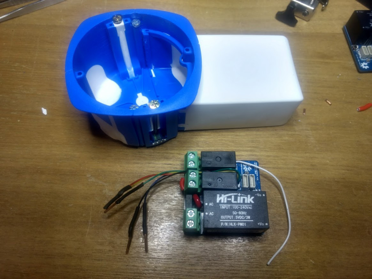
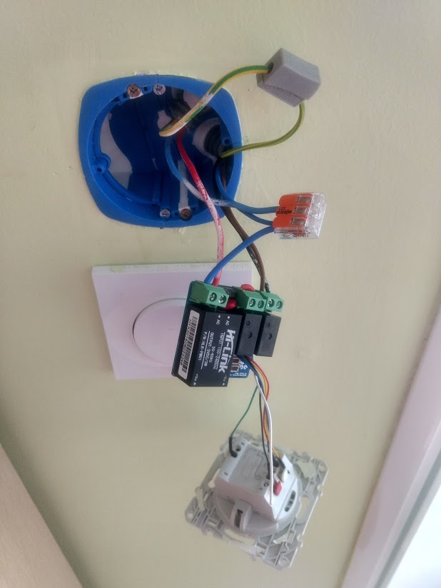
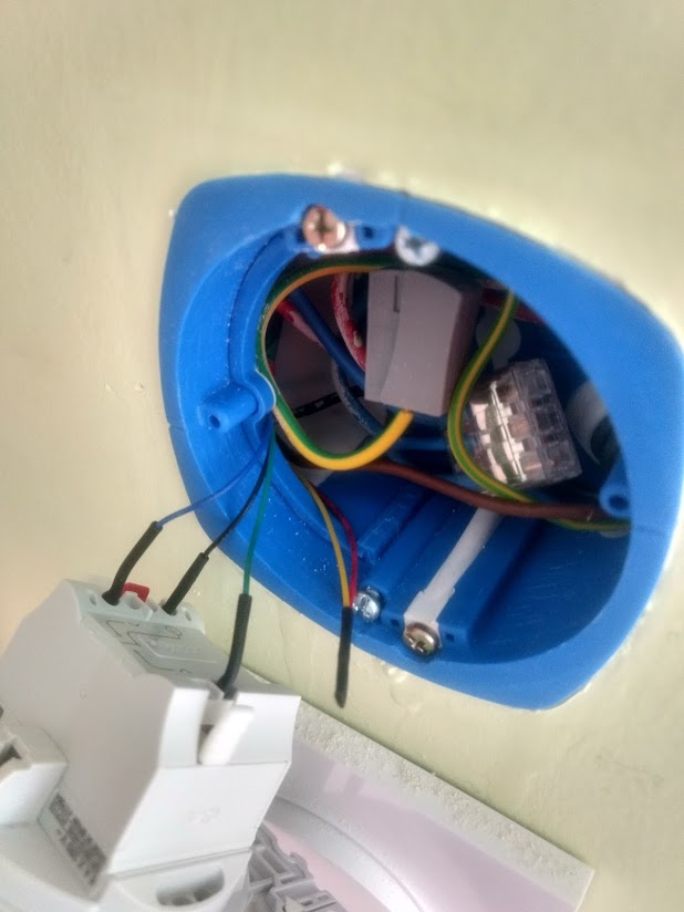
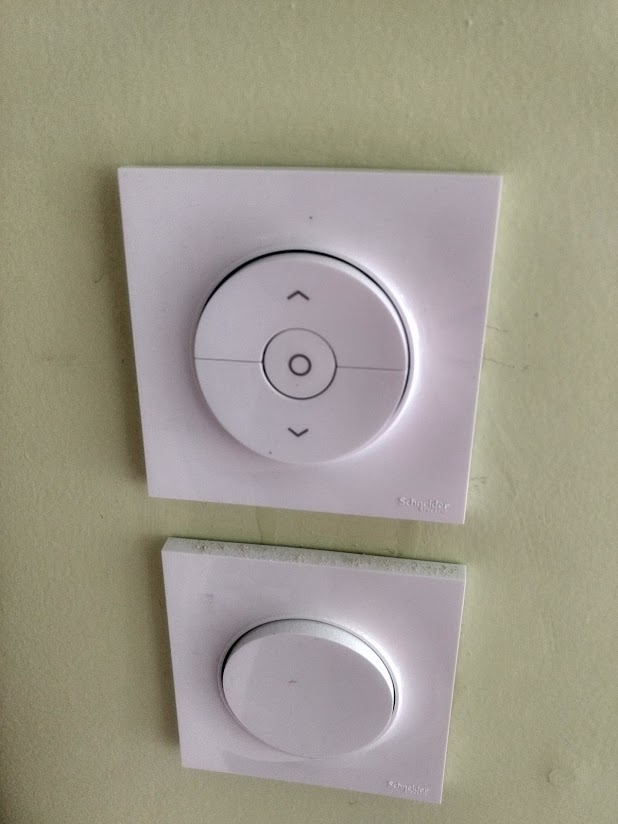
                Finnaly I find a solution with a very good WAF !
                I want to keep a sort of manual command (not gateway or controller dependant) and I don't want an expensive solution (my ODACE schneider button are quite expensive and I don't want to buy other button).
                But these button measure 38mm depth and @scalz board is about 20mm. My wall boxes are 50mm !
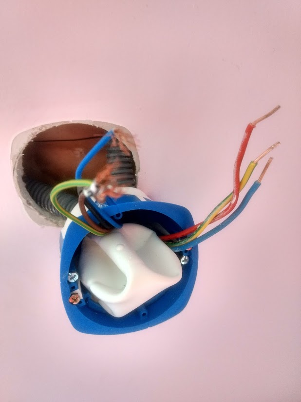
                Si I find some special wall boxes with an enclosure for home automation module. It's cheap (about 3€) and very well designed (french RT2012 compliant). I update the sketch with MY_TRANSPORT_WAIT_READY_MS so node can work alone. And I update sketch to work with bistable button. Works well on 2 windows since yesterday.
                Here is a photo before :
                0_1505166550880_IMG_20170911_233746.jpg

                1 Reply Last reply
                1
                • hekH Offline
                  hekH Offline
                  hek
                  Admin
                  wrote on last edited by hek
                  #88

                  Almost looks like this type type of part-rubber box that can be mounted without tearing down the wall:
                  0_1505167914932_1426270.jpg

                  https://www.eldirekt.se/elmaterial/elinstallation/infallda-dosor/multidosa-big-box

                  https://www.youtube.com/watch?v=pwoyoTrJr4g

                  1 Reply Last reply
                  2
                  • F Offline
                    F Offline
                    Fabien
                    wrote on last edited by
                    #89

                    Some other photos (sorry, first one is not in the same room) :
                    0_1505251878615_IMG_20170912_174015.jpg
                    0_1505251889179_IMG_20170912_110933.jpg
                    0_1505251895779_IMG_20170912_111143.jpg
                    0_1505251903528_IMG_20170912_111331.jpg

                    1 Reply Last reply
                    2
                    • F Offline
                      F Offline
                      Fabien
                      wrote on last edited by
                      #90

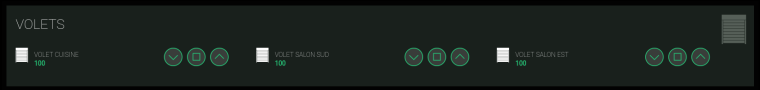
                      One test screenshot (not definitive) of my habpanel (openHab 2.0 part).
                      I'm using OpenHAB mysensors binding (from @TimO), node-red for rules, habpanel for UI, Tasker on android (for example open all RollerShuter just after morning alarm !).
                      I can access OpenHAB via nginx reverse proxy with https and on my LAN, home automation have a separate VLAN (for security reasons). Thanks a lot to @scalz for this module.
                      0_1505252614465_Capture du 2017-09-12 23-36-35.png

                      1 Reply Last reply
                      2
                      • SoloamS Offline
                        SoloamS Offline
                        Soloam
                        Hardware Contributor
                        wrote on last edited by Soloam
                        #91

                        @scalz great work, sorry to dig up the topic, but good topics never die ( :) ). Can you clarify some questions?

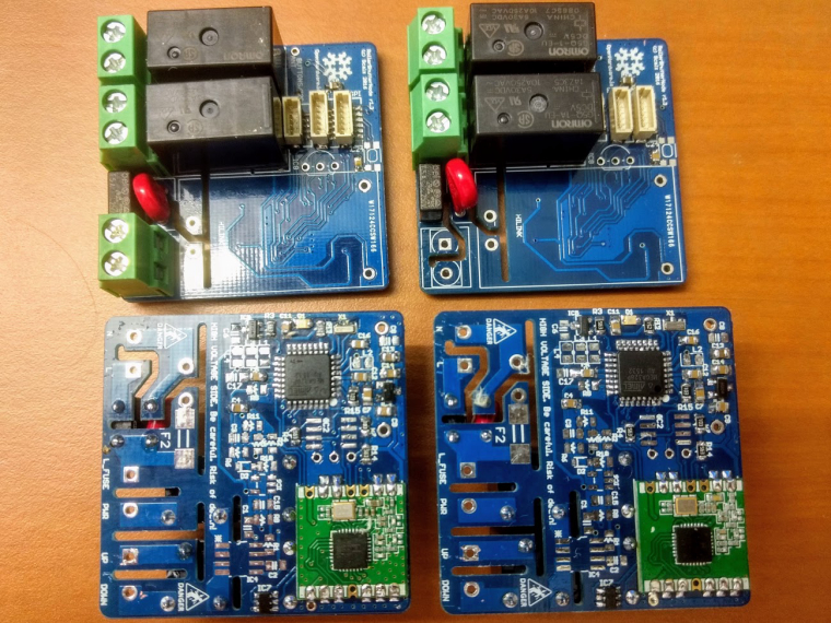
                        • Way did you used 2 different relays? Way not only one type?
                        • What is the Amp consumption of your motors? I know that 10A is overkill, but just to get one idea. Would 2A do it? (at 220V)
                        • I see that you added a 8Mhz Cristal, way not use the internal clock? It's 8Mhz
                        • I see that you use a relay driver, correct me if I'm wrong, that is because the rated coil consumption to those relays is 80mA.

                        Thank You
                        Great Work

                        1 Reply Last reply
                        0
                        • F Offline
                          F Offline
                          Fabien
                          wrote on last edited by
                          #92

                          @Soloam
                          2 relay for interlocking system and add more security.
                          I never mesure my current but it's low ... not 10A !
                          Internal clock is not very precise and can vary with external parameters like temperature. And for this project it's better to have good precision.
                          It's always better to use relay driver and not directly arduino pin.

                          SoloamS 1 Reply Last reply
                          1
                          • F Fabien

                            @Soloam
                            2 relay for interlocking system and add more security.
                            I never mesure my current but it's low ... not 10A !
                            Internal clock is not very precise and can vary with external parameters like temperature. And for this project it's better to have good precision.
                            It's always better to use relay driver and not directly arduino pin.

                            SoloamS Offline
                            SoloamS Offline
                            Soloam
                            Hardware Contributor
                            wrote on last edited by
                            #93

                            @fabien said in 💬 Roller Shutter Node:

                            @Soloam
                            2 relay for interlocking system and add more security.
                            I never mesure my current but it's low ... not 10A !
                            Internal clock is not very precise and can vary with external parameters like temperature. And for this project it's better to have good precision.
                            It's always better to use relay driver and not directly arduino pin.

                            Thank you @Fabien all very clarifying, only one thing that I don't understand (sorry, but I like to use this projects to learn and improve my personal knowledge) I still don't understand way the relays are different model numbers, from what I can see, one is 4 pins, and the other 5 pins, or I'm miss interpreting?

                            Thank you

                            1 Reply Last reply
                            0
                            • gohanG Offline
                              gohanG Offline
                              gohan
                              Mod
                              wrote on last edited by gohan
                              #94

                              one relay only needs to be on/off while the other needs to select between up and down motion.

                              1 Reply Last reply
                              1
                              • scalzS Offline
                                scalzS Offline
                                scalz
                                Hardware Contributor
                                wrote on last edited by scalz
                                #95

                                @Soloam
                                about relays, imagine there would be two same relays:

                                • two SPDT would not make sense here, plus it would add more pins.

                                • two SPST wouldn't be secure, there could be a moment where you could have both relays activated (for example in case pins are not well set on startup, or of bad sketch). That would not be great for motor.
                                  So there is one (SPST) to enable power flowing to the SPDT which toggle between UP or DOWN.

                                • there are parts on my schematic which could be optional. I always put as much footprints as I can, for reference, and especially when I need to fix something it's handy.
                                  Sure crystal could be optional, and you could burn sensebender bootloader for example, or like fabien said it's good to have. It's an AC powered node, so not really needed to try saving something. And also, if you're paranoid about sourcing cheap, and why not out of specs, atmel on aliexpress, then you have the footprints available.

                                • the relay driver is nice because it helps protecting atmel and improve reliability. It integrates all parts for relays in one package (transistors, diodes, resistors etc.) so it simplifies schematic and takes less place on pcb too.

                                • 10amp omron relays, better oversize, so you're sure they won't suffer :) and the board can be used for other stuff needing more power than rollershutters in case.

                                SoloamS 1 Reply Last reply
                                0
                                • scalzS scalz

                                  @Soloam
                                  about relays, imagine there would be two same relays:

                                  • two SPDT would not make sense here, plus it would add more pins.

                                  • two SPST wouldn't be secure, there could be a moment where you could have both relays activated (for example in case pins are not well set on startup, or of bad sketch). That would not be great for motor.
                                    So there is one (SPST) to enable power flowing to the SPDT which toggle between UP or DOWN.

                                  • there are parts on my schematic which could be optional. I always put as much footprints as I can, for reference, and especially when I need to fix something it's handy.
                                    Sure crystal could be optional, and you could burn sensebender bootloader for example, or like fabien said it's good to have. It's an AC powered node, so not really needed to try saving something. And also, if you're paranoid about sourcing cheap, and why not out of specs, atmel on aliexpress, then you have the footprints available.

                                  • the relay driver is nice because it helps protecting atmel and improve reliability. It integrates all parts for relays in one package (transistors, diodes, resistors etc.) so it simplifies schematic and takes less place on pcb too.

                                  • 10amp omron relays, better oversize, so you're sure they won't suffer :) and the board can be used for other stuff needing more power than rollershutters in case.

                                  SoloamS Offline
                                  SoloamS Offline
                                  Soloam
                                  Hardware Contributor
                                  wrote on last edited by
                                  #96

                                  @scalz this is a great work, I'm planning on ordering a couple to use on my system.

                                  Besides that, I'm most interested in the integrated Current Sensor, and planning on use it on my one PCB. I've been studding your PCB layout and reading regarding the ACS712 and is integration with the LM321. Way didn't you use the schematic on the ACS712 DataSheet (http://henrysbench.capnfatz.com/henrys-bench/arduino-current-measurements/acs712-current-sensor-user-manual/ page 12) to integrate with the LM321? I see that you use a lot more resistors and caps, and the values are not the same. Was this intencional or you did it to reuse a footprint? Would the layout on the DataSheet also work in you board? (From what I can tell it changes the sensitivity).

                                  Also I see a couple 0 Ohm resistor, I think that that is to reuse footprints correct?

                                  Thank you for your help and contribute to the community.

                                  1 Reply Last reply
                                  0
                                  • scalzS Offline
                                    scalzS Offline
                                    scalz
                                    Hardware Contributor
                                    wrote on last edited by scalz
                                    #97

                                    @Soloam
                                    Your link is about DC. He has another howto for AC, which is based on sampling adc but i was not interested in this one. I didn't want the current measurement dependant on sampling reliability and misses.
                                    So I used part of datasheet schematic, and I adjusted it to my application. If you use it in another projects, you may need to adjust resistor divider etc.
                                    0ohms needs to be soldered.

                                    1 Reply Last reply
                                    0
                                    • H Offline
                                      H Offline
                                      hitech2207
                                      wrote on last edited by
                                      #98

                                      Hi,

                                      I have been searching for a longtime for some decent rollershutter solution. I have about 12 of them and i am currently using a sonoff relay solution which works but i never really know the position if it is open or closed or pourcentage position.

                                      What your solution seems to do.

                                      Is it possible to interface this with amazon echo or google home to ask to open/close the shutter but also ask the status. Are my shutters open or closed? Or open window shutter 1 at 50%?

                                      Also there is a link to purchase 10 pcb at 21$ is the the complete solution (plug &play, including relays, connectors,,,) or is it just the board and do i need to solder everything my self?

                                      Thank you and great job at doing this! :)

                                      1 Reply Last reply
                                      0
                                      • gohanG Offline
                                        gohanG Offline
                                        gohan
                                        Mod
                                        wrote on last edited by
                                        #99

                                        You still need to get parts and solder everything together.

                                        1 Reply Last reply
                                        0
                                        • H Offline
                                          H Offline
                                          hitech2207
                                          wrote on last edited by
                                          #100

                                          Hi,

                                          Where could i buy a finished version of this hardware?

                                          alexsh1A 1 Reply Last reply
                                          0
                                          Reply
                                          • Reply as topic
                                          Log in to reply
                                          • Oldest to Newest
                                          • Newest to Oldest
                                          • Most Votes


                                          15

                                          Online

                                          11.7k

                                          Users

                                          11.2k

                                          Topics

                                          113.0k

                                          Posts


                                          Copyright 2019 TBD   |   Forum Guidelines   |   Privacy Policy   |   Terms of Service
                                          • Login

                                          • Don't have an account? Register

                                          • Login or register to search.
                                          • First post
                                            Last post
                                          0
                                          • MySensors
                                          • OpenHardware.io
                                          • Categories
                                          • Recent
                                          • Tags
                                          • Popular