💬 Roller Shutter Node
-
-
Hi guys!
I apologize because I didn't give much news about this one because I was not yet happy with few things about the overall. So I have "improved" my design :
- the size was 47x48mm. but it was not enough...edge were not enough rounded to fit perfectly in wallbox. Plus it means that it would have been difficult to make a custom insulating box because of additional thickness.
So I have reduced my board a little bit. So it should be easier to fit a custom insulating box now, I hope!
This now implies : 1.0mm connectors (no 2.54mm)..., temporarily removed the eeprom, I will try to put it again. But, there is still MYSBootloader ;) I removed ftdi connector too. It's AC powered, we have OTA, should not be a problem I guess - I have improved my routes too, clearance/creepage. I have 2.5-3mm everywhere except near the varistor but varistor does not drain lot of amp in theory. I added millings everywhere in case. All AC routes are enlarged, 100mils min. So now, there is no need to remove the solder mask for adding solder. No more tricks on this.
- this time only two components on top : relay driver + ds18b20 (replacing thermistor)
- Finally, as I think that could be a nice board for simple AC relay board, I have improved the circuit for Current sensor readings, meaning I have added some ferrite bead, and will use AGND+GND, better I think...
There is one connector fror avrspi, another one for buttons, I need to find a way for the last optional I2C.
Difficult to make this smaller! Any feedbacks? - the size was 47x48mm. but it was not enough...edge were not enough rounded to fit perfectly in wallbox. Plus it means that it would have been difficult to make a custom insulating box because of additional thickness.
-
@Fabien hehe! yep you're right, that's why I said I will try to do my best to put eeprom (and ftdi). I am just redesigning the overall to see what I can do/improve. And I hope @Tekka will come with some interesting news in future ;) but for the moment you're right. Rfm69 fit of course. Eeprom could I think, then this is ftdi that will be tricky, maybe smd pogopin 2.54 or 1.25mm pitch...or the oppposite, avrspi smd pogo and a connector for ftdi. I will see.
Looking at my pics, I see few one or two milling missing!! but that's not finished yet.
For sketch, later today, I will tell you, not complete but workable for the % opening.Thx for feedback
@scalz, between the two options if you can't fit both as normal headers, i would prefer the FTDI to have a connector and the ISP to be pogo pins :) I've been very interested in this board layout to learn from for my new AC module. Thank you for your upgrades!
-
after few hours...eeprom is back! and all routed ;)
for curious.. :)
only one 5pins connector for actuator: vcc, gnd, and- I2C+D3 int (for gesture or tactile switch extension),
- A4-A5-D3 for classic switch buttons UP/DOWN/STOP
I just need to look to my programming port..and I update this too
but looks better, cool :) -
ftdi is back too, with a reset switch in bonus :)
I have uploaded preview in first post with some details. You can see there are now 3connectors! + reset (was missing in previous rev, and thought it was too bad, so it's there.). It was not so easy to fit everything!
On 3d preview, we don't see millings but it's there (I didn't figured out how to 3d export..)So nrf revision is done, I am actually making the rfm69 changes and I order this...maybe tomorrow :)
-
:+1:
There it is ... the limit in size for this kind of boards with powersuply and 1 or 2 relays. I reach the same size on a protoboard with an arduino pro mini and its good for install inside wall swiches.Great work on that onboard arduino.(better only if you have onboard nrf24 :satisfied: )
-
ftdi is back too, with a reset switch in bonus :)
I have uploaded preview in first post with some details. You can see there are now 3connectors! + reset (was missing in previous rev, and thought it was too bad, so it's there.). It was not so easy to fit everything!
On 3d preview, we don't see millings but it's there (I didn't figured out how to 3d export..)So nrf revision is done, I am actually making the rfm69 changes and I order this...maybe tomorrow :)
I'm having trouble understanding how your AC side is connected.
Cab you show the schematic for this part ? -
I'm having trouble understanding how your AC side is connected.
Cab you show the schematic for this part ?@GertSanders Any specific prt you're struggling with? I think i can see his routes and may be of some help until Scalz gets back to you.
-
@GertSanders Any specific prt you're struggling with? I think i can see his routes and may be of some help until Scalz gets back to you.
I just realised: he is not using the two relays to give two AC sources, but uses them to switch a motor.
I was still in my mind thinking about my relay board (not published) which gives a contact with 220V when relay is closed and is AC free when relay is open.
But I will check his BOM to see which relays @scalz is using. They are smaller then the popular SONGLE relays and the pin layout is better for keeping AC away from low voltage circuitry.
-
I just realised: he is not using the two relays to give two AC sources, but uses them to switch a motor.
I was still in my mind thinking about my relay board (not published) which gives a contact with 220V when relay is closed and is AC free when relay is open.
But I will check his BOM to see which relays @scalz is using. They are smaller then the popular SONGLE relays and the pin layout is better for keeping AC away from low voltage circuitry.
@GertSanders Please inform me of those he uses when you find them. I too like the look of those on his board. Does your module use solid state relays?
-
hi guys :)
@Tmaster thx I'm glad ;) I'm not lucky this is so compact, so I couldn't have both footprint (rfm and nrf), argh so I made two rev. Don't ask me why, I still don't know, I'm going crazy :laughing:
@GertSanders schematic is already there. arg, I thought it was enough readable. what do you want to know about AC?
Here, for protecting shutter motor I had to put relays in serie.
So there is one SPST NO for "power". When enabled, if I remember right, it moves UP. Send logic 1 to the 2nd relay, and as it is SPDT it will go DOWN. Disable the first one, no more juice...
if motor is AC, the 12_220 pad need to be connected to one LIVE.
if motor is DC, 12_220 need to be connected to your DC source.Relays I'm using are well known OMRON. G5Q. I choosed them exactly for what you said, size and footprint. Nice price at tme, I have a bunch of them ;) No ad :) I have other more powerful 16a too, for a special multi relays board...
I have modified a little bit my thing. Boards are ordered. I will try to upload asap. I'm a bit busy and would like to check few things before, you know..Oh, and I have other cool projects ongoing, I hope you will like them ;)
-
@GertSanders Please inform me of those he uses when you find them. I too like the look of those on his board. Does your module use solid state relays?
@Samuel235
My board is using the cheap Songle relays (5V switches 10A 220VAC).In the mean time I found out he is using G5Q by OMRON series. They have a Panasonic equivalent at Aliexpress, I will try those.
-
hi guys :)
@Tmaster thx I'm glad ;) I'm not lucky this is so compact, so I couldn't have both footprint (rfm and nrf), argh so I made two rev. Don't ask me why, I still don't know, I'm going crazy :laughing:
@GertSanders schematic is already there. arg, I thought it was enough readable. what do you want to know about AC?
Here, for protecting shutter motor I had to put relays in serie.
So there is one SPST NO for "power". When enabled, if I remember right, it moves UP. Send logic 1 to the 2nd relay, and as it is SPDT it will go DOWN. Disable the first one, no more juice...
if motor is AC, the 12_220 pad need to be connected to one LIVE.
if motor is DC, 12_220 need to be connected to your DC source.Relays I'm using are well known OMRON. G5Q. I choosed them exactly for what you said, size and footprint. Nice price at tme, I have a bunch of them ;) No ad :) I have other more powerful 16a too, for a special multi relays board...
I have modified a little bit my thing. Boards are ordered. I will try to upload asap. I'm a bit busy and would like to check few things before, you know..Oh, and I have other cool projects ongoing, I hope you will like them ;)
@scalz
No worries about the schematic. I was just confused (but it is clear now). Do you have a link for the relays ? I can find equivalents from Panasonic on the Aliexpress site. Not sure what vendor you mean with TME (url?)I always look forward to your projects :-)
-
@GertSanders I'm reassured ;) I try to keep things understable but sometimes my brain is confused lol
Relays I'm using:
http://www.tme.eu/en/details/g5q-1-eu-5dc/miniature-electromagnetic-relays/omron/g5q-1-eu-5vdc/
http://www.tme.eu/en/details/g5q-1a-eu-5dc/miniature-electromagnetic-relays/omron/g5q-1a-eu-5vdc/
The cheaper I found at a trusted source. nice isn't it? -
@GertSanders a last note..that's not my very last schematic rev. On this previous one, you can see I was protecting globally the board with a 5Amp fuse, good for relays here (shutter motor don't use so much), but what about hilink?? not rated for 5a at all! So on bottom, I have added a smd fuses for the hilink only. So there are two fuses on my board now.
Link of the smd fuse :
http://www.mouser.com/ds/2/9/MF2410 Datasheet2013-247737.pdf
I never tried this one so I will tell you if it works well. I have 0.8 and 1amp ref. I think it's largely enough secure...varistor, temp sensor, two fuses...lol I don't know if there are so much things in commercial products..If there is a problem on the board, lot of chance there is a bigger problem somewhere else lol -
Hey there :)
sorry for delay, busy busy time..
Just to say i have uploaded latest pics , and I will try to make a vid of the thing in action as soon as i can..
See you soon! -
hi
my node is still working well..i'm trying to reorganize my priority, I'm enough confident to release :blush:
for the report, I don't remember if I explained how i did my acs calibration so..Here a pic of an homemade load, don't laugh, it can be useful :)
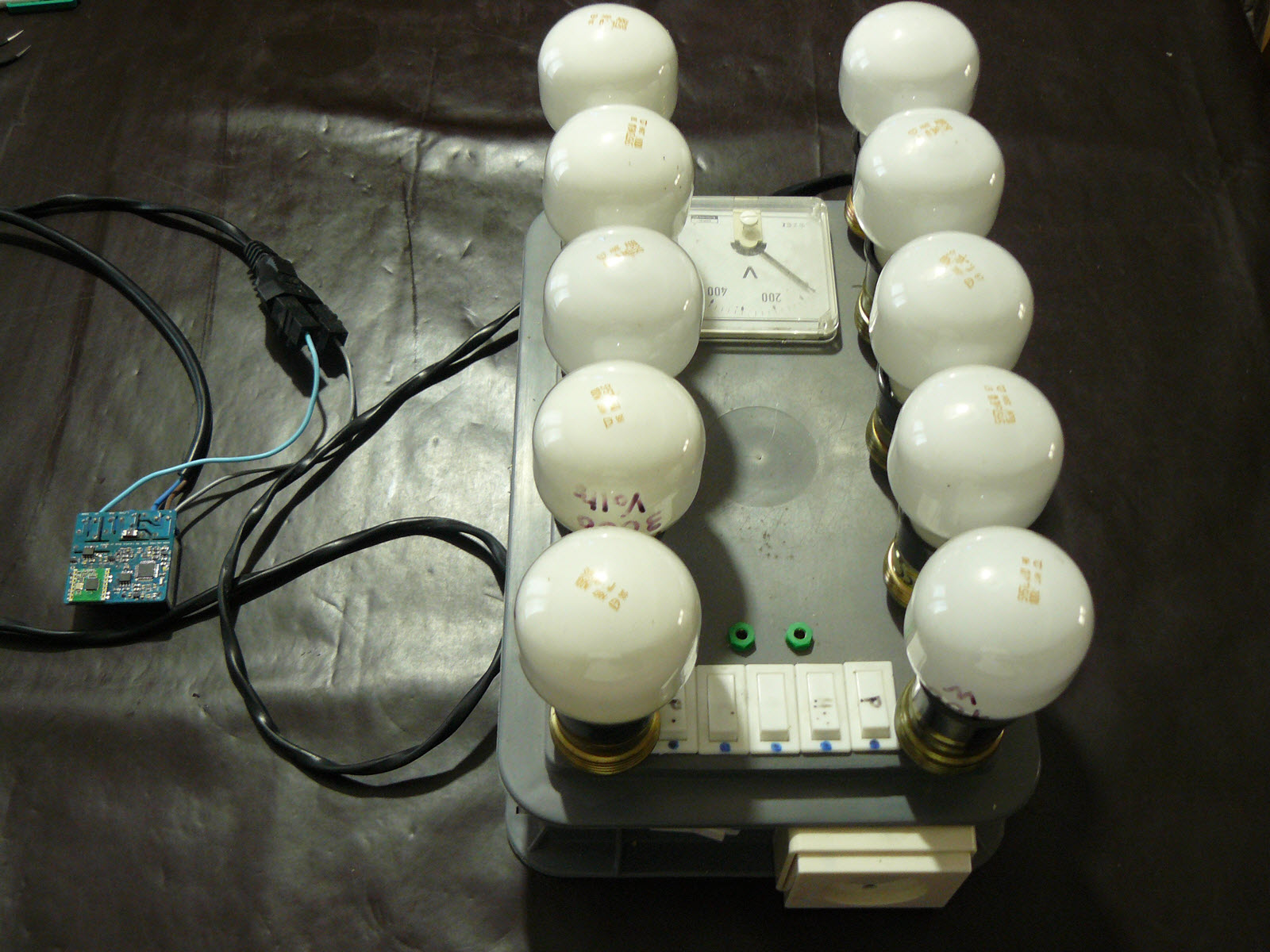
I can power 1 to 5 incandescent bulbs separately on a row, and there is also a switch to power completely the other row. So I was able to measure 0-1000W by 100W step. cool :)And the report after calibrating a bit opamp circuit
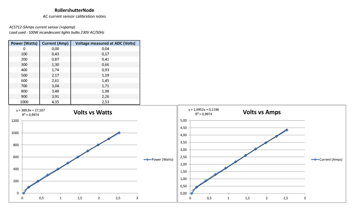
So you can see that's pretty nice.
I know there could be some debate about the way I decided to do the endstop monitoring. I could have used other ways than acs sensors. but after footprint evaluation, cost, versatility etc..I preferred imho this way.
Plus, like this, by using the opamp, I can have a nice curve for a 3V adc, keeping atmel 3v, and saving some uc cycle without doing sampling for 50hz etc...and I can use some fast adc for faster..
Hello! It looks like you're interested in this conversation, but you don't have an account yet.
Getting fed up of having to scroll through the same posts each visit? When you register for an account, you'll always come back to exactly where you were before, and choose to be notified of new replies (either via email, or push notification). You'll also be able to save bookmarks and upvote posts to show your appreciation to other community members.
With your input, this post could be even better 💗
Register Login