2.0 Discussion: Units, sensor types and protocol
-
I dont know why we have to limit some S_type to a number of V_types. Why not just let a S_type have 'all' V_types... User can be more flexible
If I wanted node could send
S_MOTION V_TRIPPED 1 (motion tripped)
S_MOTION V_ARMED 0 (no longer armed)
S_MOTION V_LEVEL 24 (motion quality 24 of 255) (probobly animal)controller decides S_MOTION V_RESET 1
(order not thought of at all, needs to be fixed)
#DEFINE S_DOOR 1 #DEFINE S_MOTION 2 #DEFINE S_SMOKE 3 #DEFINE S_BINARY 4 #DEFINE S_DIMMABLE 5 #DEFINE S_WINDOW_COVER 6 #DEFINE S_THERMOMETER 7 #DEFINE S_HUMIDITY 8 #DEFINE S_BAROMETER 9 #DEFINE S_WIND 10 #DEFINE S_RAIN 11 #DEFINE S_UV 12 #DEFINE S_WEIGHT_SCALE 13 #DEFINE S_POWER 14 #DEFINE S_HEATER 15 #DEFINE S_DISTANCE 16 #DEFINE S_LIGHT_SENSOR 17 #DEFINE S_NODE 18 #DEFINE S_LOCK 19 #DEFINE S_IR 20 #DEFINE S_WATER_METER 21 #DEFINE S_AIR_QUALITY 22 #DEFINE S_CUSTOM 23 #DEFINE S_DUST 24 #DEFINE S_PH 25 #DEFINE S_SCENE_CONTROLLER 26 #DEFINE S_NODE 255 #DEFINE V_CONFIG1 1 #DEFINE V_CONFIG2 2 #DEFINE V_CONFIG3 3 #DEFINE V_CONFIG4 4 #DEFINE V_CONFIG5 5 #DEFINE V_VAR1 6 #DEFINE V_VAR2 7 #DEFINE V_VAR3 8 #DEFINE V_VAR4 9 #DEFINE V_VAR5 10 #DEFINE V_ARMED 11 #DEFINE V_STATUS 12 #DEFINE V_WATT 13 #DEFINE V_PERCENTAGE 14 #DEFINE V_STOP 15 #DEFINE V_LEVEL 16 #DEFINE V_MAX 17 #DEFINE V_MIN 18 #DEFINE V_RESET 19 #DEFINE V_DEW_POINT 20 #DEFINE V_MODE 21 #DEFINE V_ANGLE 22 #DEFINE V_RATE 23 #DEFINE V_VOLTS 24 #DEFINE V_AMPS 25 #DEFINE V_PRESENTATION 26 #DEFINE V_BATTERY_LEVEL 27 #DEFINE V_RESET 28 #DEFINE V_TIME 29 #DEFINE V_ID 30 #DEFINE V_LOG_MESSAGE 31 #DEFINE V_SKETCH_NAME 32 #DEFINE V_SKETCH_VERSION 33 #DEFINE V_FIND_PARENT 34 #DEFINE V_CHILDREN 35 #DEFINE V_VERSION 36 #DEFINE V_INCLUSION_MODE 37 #DEFINE V_GATEWAY_READY 38 #DEFINE V_STATUS 39 #DEFINE V_IR_SEND 40 #DEFINE V_IR_RECEIVE 41@Damme said:
I dont know why we have to limit some S_type to a number of V_types. Why not just let a S_type have 'all' V_types... User can be more flexible
As described at the time I write, the proposed taxonomy of values isn't really as heirarchical as it's presented.
You can also parse the meaning from V code to S code:Ah, we have a V_LEVEL value, that means it represents a one dimensions continuum But what does that continuum represents? Oh, I see the variable is also tagged with S_TEMPERATURE That means the continuum is temperature in degrees CThat is, the V code tells you something of the structural concept, and the S code adds some degree of semantics (like dimension and unit).
So you could also invert the displayed hierarchy and show which S codes are available for a given V code
-
Hold the presses.
I've happily engaged in the collaborative process of cleaning up the variable taxonomies of V 1.4b here.
But we keep coming to conceptual tricky parts. Some of that is inherent, but in thinking deeper about it, i've come to the conclusion that a good part of what makes it hard to resolve cleanly is that we are trying to cram too much information into too few bits of variable metadata which has to be included in every packet.
So rather than reforming S and V codes, I'm thinking a more radical approach is needed, to make the system both more flexible and simpler. Part of that comes from identifying what metadata about a variable is static and what needs to be dynamic, and then moving the static part out of the normal OTA operations. That turns out to make the taxonomy much more tractable and flexible while simplifying the node firmware.
Guess what - even child ID turns out to be metadata in this approach, rather than addressing.
Here's the sketch of the new approach.
http://forum.mysensors.org/topic/308/another-way-of-organizing-variables
It's sufficiently different that I expect it may encounter resistance - from the natural and appropriate fear of breaking too much (I share that concern). But it just may turn out to be sufficiently attractive to be worth it. Have a look. And now would be the time to consider such a break - with RadioHead and OTA programming support also in the air.
-
@Yveaux said:
[dissing start] Did you think about sending the sensor type only once, durig presentation? There really is no need to send it with each set/req message as it is static for the duration of the connection. For Vera and the like this probably means you should buffer these values in the gateway... [dissing end]
Yes, it would save a byte. But it could be very useful for a simpler controller (which can determine sensor type from each and every message) and when displaying sniffing data ;).
This would only leave 3 COMMAND types left. REQ, SET and STREAM. Where STREAM-data probably could be handled by S_NODE (internal). This means just 1 bit is needed for a SET/REQ flag. But @ToSa would have to feedback on this.
@hek said:
This would only leave 3 COMMAND types left. REQ, SET and STREAM. Where STREAM-data probably could be handled by S_NODE (internal). This means just 1 bit is needed for a SET/REQ flag. But @ToSa would have to feedback on this.
I switched the bootloader code between using stream and using simple internal messages - at the end doesn't matter as long as it's simple enough to dis-samble and assemble a packet without a lot of additional code overhead.
-
@hek said:
FYI: Sleeping sensors (who also can be woken by a interrupt on a pin) will have a hard time keeping time without clock module or by fetching time from server at each wakeup from pin trigger.
Sleeping nodes may have a hard time averaging in some cases too.. But your point is well taken and it is a real concern.
One of the sleep libraries calibrate the RC watchdog timer against the main clock, so it can make a good guess for adjusting milliseconds upon each wakeup. That could help for a simple sleep, but not for waking up from an interrupt.
So the problem child is a node for which all the following apply:
- sleeps
- is awoken by interrupts at unpredictable intervals
- has no local RTC
- has accumulated variables
One option would just be to ignore the accumulated time feature for the subset of nodes in that category; for them, you have to fall back to where would be be if I had never spoken up about tracking time. For other nodes, the tracking & reporting of accumulation time can be an enhancement, as described in an earlier message.
But suppose we DO want to go further and determine accumulation time for all nodes, even the above.
(Sigh. I acknowledged that there was a simplicity advantage to not dealing with time, and that just using the local node's millis() was the simplest but not only way to handle time; and that does handle most cases but not the above)
System Time approach 1: Master Clock Broadcast to nodes
The hub will have the master clock, using its millis(). Periodically it will broadcast the value of this to all nodes. A node could also request a time be sent. We could apply a crude delta to adjust this according to number of hops and typical transmission time, or not - we don't need anywhere close to millisecond accuracy. Each node would maintain a delta between its own millisecond clock and the broadcast millis and adjust that every time it receives that broadcast. (Smart nodes could even use a computed time scaling factor to adjust for differences in their clock vs the master). When for any reason has a need to estimate the current time (including but not limited to the case of having been powered up from sleeping by an interrupt AND needing to repost accumulations with more precision than it can estimate), the node can either wait for the next broadcast, or request one.
System Time approach 2: Track accumulation times in the hub
Whenever an accumulation period is started, the node will send a message to the hub to that effect (telling it which variable is involved and an incrementing reset count). This could be triggered by a commanded or manual reset, or by the automatic reset of an external weather station or service, or whatever. Then it would send the reset count (V_RESET_COUNT) rather than the accumulated time along with accumulation based values. The hub can look at its current time, and at the recorded time of the last reported reset of that variable, to compute for itself the elapsed time. The reset count makes sure both sides are sync'd as to which reset they are talking about. Both the "Starting accumulation period #n for (variable)" and the "reporting accumulated value for (variable)" messages travel from node to hub, and their travel times will roughly cancel out, at least well enough.
The former approach is more powerful. It better supports rolling averages. And it would provide a flexible "MySensors network time" framework for future features, like reporting event times or periods more accurately.
For example, I've considered putting two motion detectors at angles and with masks such that one could usually detect which way somebody went through a doorway by the trigger times, or at different place in a hallway. I'm not proposing to support that directly at this time, but when it comes up, if each node had the option of knowing the hub's master clock time to within tens of milliseconds or better, that could be a useful base upon which to build.
[Total aside. My ambition for another nRF + Arduino system is more precise than this, possibly even enough to do PWM of 60 Hz mains powered lights without a local zero crossing detector - not yet determined. That's why I connect the nRF24L01+'s IRQ output to Arduino pin 8 = ICP1, even if I'm not using interrupt driven nRF code. If the nRF's receive interrupt is enabled, this allows the ATMega328p to get a very accurate time of reception using Timer 1 if it wants, even in polling mode without interrupts. And if I ever do want to interrupt the ATMega from the nRF, I can use the capture interrupt, while leaving INT0 and INT1 on pins 3 & 4 for other uses. The above first option is a smaller, simpler version of that design, adapted for the needs of a sensor network]
@Zeph said:
But suppose we DO want to go further and determine accumulation time for all nodes, even the above.
...
System Time approach 1: Master Clock Broadcast to nodes
...
System Time approach 2: Track accumulation times in the hubI'm in favor of approach 1 as well - and an optional addition to the MySensors class to keep track of time. Only specific sensor types would use this feature - interesting mainly for actuators rather than sensors:
Let's assume you use a relay to turn on/off your garden watering while you are on vacation. The network breaks (controller or gateway or whatever node needed to relay messages).
- If the sensor node itself knows about the time and the schedule for watering, it can turn on and off the watering itself. If there is an issue with the communication, the time would not be 100% accurate over time but still good enough.
- If the sensor node relies completely on the controller for time and (worst case) the communication breaks just between the start watering and stop watering command you can imagine what happens...
Knowing about the time heavily reduces the single points of failure. The protocol already covers the "request time" communication so this should be relatively easy to implement...
- controller sends a time broadcast every e.g. 15 minutes
- only the nodes interested in time care about it and update their internal time
- when a node needs the current time it calculates it based on the last timestamp received, the millis() when it was received and the current millis...
Doesn't solve the sleep issue (as long as you don't want to submit a separate "get time request" every time you wake up) but at least for sensors that are not battery powered (relay nodes in most cases are not) it's a feasible approach.
This is probably worth a separate thread :)
-
@Zeph said:
But suppose we DO want to go further and determine accumulation time for all nodes, even the above.
...
System Time approach 1: Master Clock Broadcast to nodes
...
System Time approach 2: Track accumulation times in the hubI'm in favor of approach 1 as well - and an optional addition to the MySensors class to keep track of time. Only specific sensor types would use this feature - interesting mainly for actuators rather than sensors:
Let's assume you use a relay to turn on/off your garden watering while you are on vacation. The network breaks (controller or gateway or whatever node needed to relay messages).
- If the sensor node itself knows about the time and the schedule for watering, it can turn on and off the watering itself. If there is an issue with the communication, the time would not be 100% accurate over time but still good enough.
- If the sensor node relies completely on the controller for time and (worst case) the communication breaks just between the start watering and stop watering command you can imagine what happens...
Knowing about the time heavily reduces the single points of failure. The protocol already covers the "request time" communication so this should be relatively easy to implement...
- controller sends a time broadcast every e.g. 15 minutes
- only the nodes interested in time care about it and update their internal time
- when a node needs the current time it calculates it based on the last timestamp received, the millis() when it was received and the current millis...
Doesn't solve the sleep issue (as long as you don't want to submit a separate "get time request" every time you wake up) but at least for sensors that are not battery powered (relay nodes in most cases are not) it's a feasible approach.
This is probably worth a separate thread :)
Yes, and to extend this even further it would be great to be able to distribute/push simple rules all the way out to the nodes. It might be enough with simple scheduler-commands to start with but this could easily support even advances scenarios. The question is where to set the cuttingpoint...
The most extreme solution would be to allow a graphical rule engine on the controller which automatically generates a sketch, compiles it and sends it out OTA to the node.
Definitely worth discussing in a new thread...
-
Yes, and to extend this even further it would be great to be able to distribute/push simple rules all the way out to the nodes. It might be enough with simple scheduler-commands to start with but this could easily support even advances scenarios. The question is where to set the cuttingpoint...
The most extreme solution would be to allow a graphical rule engine on the controller which automatically generates a sketch, compiles it and sends it out OTA to the node.
Definitely worth discussing in a new thread...
@hek said:
Yes, and to extend this even further it would be great to be able to distribute/push simple rules all the way out to the nodes. It might be enough with simple scheduler-commands to start with but this could easily support even advances scenarios. The question is where to set the cuttingpoint...
For the level of protocol under current discussion, the cuttingpoint could just be giving nodes an optional sense of time (using broadcast packets to keep in sync with the master as needed). And making use of that time as part of the (optional) accumulation enhancement for some variables.
What else they do with that time at higher layers would continue to evolve in the future. We don't have to bite it all off now.
-
V_R_PERCENTAGE - Red component % <int>
V_G_PERCENTAGE - Green component % <int>
V_B_PERCENTAGE - Blue component % <int>
V_W_PERCENTAGE - White component % <int>Just a hundred steps might be to low, especially for green in the lower end which the eye sees much brighter.
Please consider floats or per thousand instead. -
Ok! Didn't know that. But couldn't the sensor code adjust this with some sort of color curve?
@hek
That would probably do it, however one would need to be defined and standardized so that all behaves the same. One more clever than me needs to propose how the curve would look tough. -
S_RGBW - RGBW Light
V_STATUS - 1 - turn on, 0 = turn off
V_R_PERCENTAGE - Red component % <int>
V_G_PERCENTAGE - Green component % <int>
V_B_PERCENTAGE - Blue component % <int>
V_W_PERCENTAGE - White component % <int>Ain't it better to split up S_RGBW to two different types. W is already present in full R, G, and B. For example i have implemented Philips Hue and there is a difference in fixture types some do RGB some only W. If an user would implement such with mysensors the same option can be possible. An S_RGBW declaration for a W only would indicate RGB capabilities and maybe cause confusion.
Just a hundred steps might be to low, especially for green in the lower end which the eye sees much brighter.
Agree, but thousands could be too much (which never is the case of course), maybe 0-255 would be sufficient and widely used (all though not as precise in steps as with thousands)? Also the W_PERCENTAGE should be left out because this is full R,G,B or similar calibrated R,G,B levels (which is quite difficult to do at every possible level) with the end result it then in fact is a brightness level instead of a white component.
An addition could be S_HSB/S_HSV with float,float,float (0.0-360.0, 0.0-100.0, 0.0-100.0)? Also i think the color presentation should be or calibrated on the device or in the controller. Even some of those Philips Hue's fixtures are often controller side calibrated (better said color index modified after color selection)....
-
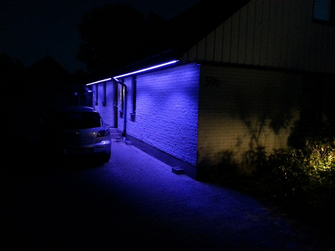
I actually have RGBW led strips mounted around our house. W is indeed its own component (Warm White in my case). So it will stick ;)
(Warm White using the special W-component)
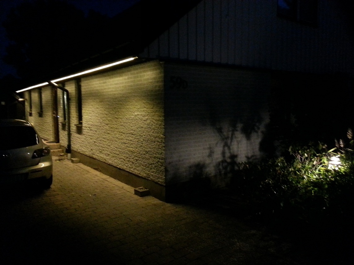
Cold white (RGB activated)
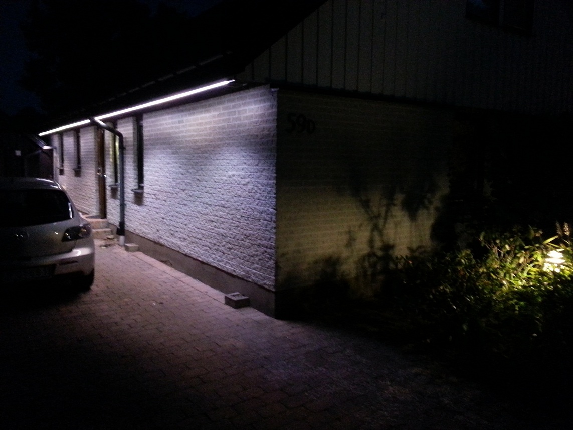
Crazy
@hek
Ahhh... understood :)... Splitting those up will not be an option then because it could then create a numerous amount of options....A S_HSB would be nice though, even if it would only be ints....:
V_STATUS - 1 - turn on, 0 = turn off
V_H_DEGREE - Degree (0-360)<int>
V_S_PERCENTAGE - Saturation % <int>
V_B_PERCENTAGE/V_V_PERCENTAGE - Brightness/Value % <int>
V_WATT - Watt <int>
V_WATT_MAX - Max watt value
V_WATT_MIN - Min watt value
V_WATT_AVERAGE - Min watt value
V_WATT_RESET - Reset max/min valueI must say it is a personal request :$....
[Edit]
But switching to LEVEL and using 0-255 would be ok (if we need it :wink:).
It would create space to add the HSB/HSV option ;)
-
What's wrong with setting lights at 1.475% Is percentage limited to integer?
Let's be very explicit about that. Is the idea that all values accept only integers unless they say they have the option of using floats? If so that should be made clear in the list.
Another thing that needs to be more clear is how to handle multiple V codes for the same sensacturator (like the RGB or HSV lights).
- Is a sensor expected to report all of them?
- Is an actuator expected to respond to all of them?
- How do both sides stay in sync about subsetting?
By the way, there is a distinction to be made between RGB lights (three blendable primaries able to synthesize many colors in a predictable and fairly standard way) and multichannel control of N lights of arbitrary colors. RGBW is another thing entirely. The W could be cool or warm white. For that matter the fourth color could be yellow or violet. It's not a color space.
If the RGB channels blend I'd implement it as an RGB light plus a monochrome light, because there is no RGBW color space. If they don't blend I'd implement it as 4 monochrome channels, the same way I'd implement a Yellow and Green pair that didn't blend.
What's wrong with setting lights at 1.475% Is percentage limited to integer?
It just not represents any absolute bit value for a specific color, it is an approximate. If for example you have a fixture which does 255 steps and you want to set it at step 40. you will need to send 15.682.....%. But what if you would send 15.770... ? Due to the nature of floats it could be rounded down or up to 40 or 41 and especially in the lower steps of a color the difference would be seen if this is a mix of on of the RGB values, and even more as all the RGB values are send in percentages. A percentage would only be usable (But even then it's still an approximate) with 32 bit or analogue blend RGB fixtures. There ain't a lot of these.
@zeph said:
If the RGB channels blend I'd implement it as an RGB light plus a monochrome light, because there is no RGBW color space. If they don't blend I'd implement it as 4 monochrome channels, the same way I'd implement a Yellow and Green pair that didn't blend.
I do agree with you, and you're totally right, but:
@john said:
Splitting those up will not be an option then because it could then create a numerous amount of options....
In other words it could eat up the possible S_TYPE's
@hek
Please disregard this one, it wouldn't :"it would create space to add the HSB/HSV option".
But, couldn't it be an option to add the HSB/HSV variables to the S_RGBW? because if the presentation stays you would only have to send the vars that are supported, and the type S_RGBW could be renamed to something like S_LIGHT_COLOR? -
The question is where the actual calculation is done between RGB and HSB/HSV. Should it be done on the Arduino side or controller? Nothing stops you from making a fancy HSB/HSV GUI on your controller but the actual values send to the actuator is RGB. But my knowledge of color scales is a bit limited and I'm probably missing something?
-
The question is where the actual calculation is done between RGB and HSB/HSV. Should it be done on the Arduino side or controller? Nothing stops you from making a fancy HSB/HSV GUI on your controller but the actual values send to the actuator is RGB. But my knowledge of color scales is a bit limited and I'm probably missing something?
It depends, if the HSB scale is purely in integers you will have about 3.600.000 options (including brightness steps) which is much less then 16 bit 0,0,0 - 255,255,255 scale. But this scale ain't specific in int's it is an implementation chosen scale. If choosing for ints, yeah keep the RGB, if going to floats, add it next to the RGB.
probably missing something?
The main difference is that with pure 16 bit you will have whole bit numbers and with degrees there is more then just go from 359 to 360/0. you could use 359,00 to 359,99 which gives an extra 990.000 extra red combinations (including saturation and brightness) with absolute 16 bit you stick with whole ints/bytes limiting the possible fixtures light high "resolution" capabilities.
Also because of the nature of HSB with higher color resolution possibilities you will always have the possibility to find the closest 16 bit neighbor or even the exact bit value because of higher to lower "spectrum" resolution.
With the above if you would leave out the brightness you would have a higher color resolution 255,254,255 is one step lower green form maximum, you can't go to 254.9 right? in degrees i think green is 120, you could go to 119.99999. because the degrees are not fixed to a whole as a byte is.
Because of more steps calibrating un-calibrated fixtures/leds (for example with the green mentioned earlier) can be more precise. Also HSB is more human perspective then fixed bits.
Maybe the above shines a light on the difference?
RGB is just a brightness setting of a specific color, HSB is pure color selection, intensity setting, and the brightness of these.
Personally:
HSB is nice to have, but from personal needs i have enough convertion functions (hsb->rgb and vice, hsb -> kelvin, etc...) to convert.Should it be done on the Arduino side or controller?
I would let the controller do the actual conversions and let the device spec it's capabilities.
-
@hek said:
S_RGBW - RGBW Light
V_STATUS - 1 - turn on, 0 = turn off
V_R_PERCENTAGE - Red component % <int>
V_G_PERCENTAGE - Green component % <int>
V_B_PERCENTAGE - Blue component % <int>
V_W_PERCENTAGE - White component % <int>
V_WATT - Watt <int>
V_WATT_MAX - Max watt value
V_WATT_MIN - Min watt value
V_WATT_AVERAGE - Min watt value
V_WATT_RESET - Reset max/min valuesOne of the areas where the spec is very unclear is when a variable is writable and where it's only reportable (read only).
For example, can I set the watts to 20 above (or for S_DIMMABLE) in order to tell the light how much power I want it to use? Seems like a valuable option. How am I supposed to know?
What if we made the write/report/trigger function explicit:
S_RGBW - RGBW Light
W_STATUS - 1 - turn on (100%), 0 = turn off (0%)
W_R_PERCENTAGE - Red component % <int>
W_G_PERCENTAGE - Green component % <int>
W_B_PERCENTAGE - Blue component % <int>
W_W_PERCENTAGE - White component % <int>
R_WATT - Watt <int> - current instantaneous or short term average value
R_WATT_MAX - Max watt value since last reset
R_WATT_MIN - Min watt value since last reset
R_WATT_AVERAGE - Min watt value since last reset
T_WATT_RESET - Reset max/min/avg value
W variables can be written to; the current value can also be queried
R variables can only be reported (automatically or by query)
T variables are triggers, writing to them triggers some actionThis gives guidance to both the sketch writer for the node, as well the controller adapter writer in knowing what they can do with each variable a node presents.
The actual numeric values for R, W and T codes could be interspersed or non-overlapping ranges could be reserved for each (eg: 1-100 for R, 101-200 for W and 201-255 for T)
@Zeph it all depends on how skilled programmer and how nerdy you are. if you want to set a lamp power with V_WATT great, thats nerdy! but in not, just dont read any thing from v_watt. .. there is no such thing as a read only variable, all depends on if you listen to incoming messages of that type or not.... I think you over-think this a bit. The atmega328 is a rather small mcu and wont be able to magically do tons of stuff. how to know what is what, well every home automation system should have a manual :) Write it down.