💬 Various bootloader files based on Optiboot 6.2


  • Hardware Contributor

    @GertSanders said:

    @Samuel235
    I have no issues with ftdi uploads at 8Mhz internal and 38k upload speed on my nodes. Even for 25k byte sketches.

    I've been told that it should work but atmel do not advise it or support it apparently. There are chances that it wont work and mine doesn't. I had the discussion regarding it in my nodes topic but the conversation just dropped off and went stale.


  • Hardware Contributor

    @Samuel235
    That depends on the upload speed. At higher speeds the error on the frequency of the internal oscillator gets more important. It can be off by several percent (from 8mhz) and then avrdude can fail. I have experimented with 9600 baud and there the deviation of the internal 8mhz has to be severe before the serial uploads starts to feel the effect.
    So try using a 8Mhz boot loader prepared for an 9600 baud upload.


  • Hardware Contributor

    @GertSanders, i did do, that's the latest solution i tried. No joy.


  • @GertSanders Thanks for explanation. It confirms what I imagine !

    I am using a 10MOhm resistor but not the full deep sleep as I want to periodically send the battery.
    I will try it because 1-2 uA is very low 😉


  • @Samuel235 No issue to with the FTDI.
    I just found a small problem due to the Arduino IDE. As I often change board (from UNO to different bootloader) I discover that the menu is sometime not coherent with the real setting. So I found that selecting two or three times board parameters (including port) is the solution to avoid communication issue.


  • Hardware Contributor

    @Samuel235
    Would you want to try a bootloader with an upload speed of 4800 ? I can make that for 8Mhz if you want (just to test)?


  • Hardware Contributor

    @GertSanders, that would be fantastic if you wouldn't mind. Its for my in wall light switch custom made node that you're following. Thanks you, much appreciated.


  • Hardware Contributor

    @Samuel235

    here is the boot loader in 2 versions: one will flash port PB0 and the other does not.

    You need to use the following fuse settings in the board file:

    bootloader.low_fuses=0xE2
    bootloader.high_fuses=0xDE
    bootloader.extended_fuses=0x06

    1_1458903521561_optiboot_atmega328_08M_004800_NOLED.hex

    0_1458903521561_optiboot_atmega328_08M_004800_B0.hex

    I saw that you use high fuse 0xDA

    I'm assuming you use a boot loader larger then 512 bytes. Optiboot fits inside 512 bytes, so we need to define a space of 256 words (1 word = 2 bytes in AVR 8bit).


  • Hardware Contributor

    @Samuel235

    For my boot loaders based on Optiboot 6.2, I normally use high fuse set to 0xDE

    Extract from my boards.txt file:

    menu.mhz=CPU Speed
    menu.bod=Brown Out Detection

    28PinBoard.name=atmega328p based - 28 pin DIL

    28PinBoard.upload.tool=arduino:avrdude
    28PinBoard.upload.protocol=arduino
    28PinBoard.upload.maximum_size=32256
    28PinBoard.upload.maximum_data_size=2048

    28PinBoard.bootloader.tool=arduino:avrdude

    28PinBoard.bootloader.unlock_bits=0x3F
    28PinBoard.bootloader.lock_bits=0x0F

    28PinBoard.build.core=arduino:arduino
    28PinBoard.build.mcu=atmega328p

    28PinBoard.build.board=AVR_GERTSANDERS28PinBoard
    28PinBoard.build.variant=28PinBoard

    28PinBoard.menu.bod.4v3=4V3
    28PinBoard.menu.bod.4v3.bootloader.extended_fuses=0x04
    28PinBoard.menu.bod.2v7=2V7
    28PinBoard.menu.bod.2v7.bootloader.extended_fuses=0x05
    28PinBoard.menu.bod.1v8=1V8
    28PinBoard.menu.bod.1v8.bootloader.extended_fuses=0x06
    28PinBoard.menu.bod.off=Disabled
    28PinBoard.menu.bod.off.bootloader.extended_fuses=0x07

    28PinBoard.menu.mhz.8Mi-38K4-D8= 8Mhz - internal - 38K4 - D8
    28PinBoard.menu.mhz.8Mi-38K4-D8.bootloader.low_fuses=0xE2
    28PinBoard.menu.mhz.8Mi-38K4-D8.bootloader.high_fuses=0xDE
    28PinBoard.menu.mhz.8Mi-38K4-D8.build.f_cpu=8000000L
    28PinBoard.menu.mhz.8Mi-38K4-D8.upload.speed=38400
    28PinBoard.menu.mhz.8Mi-38K4-D8.bootloader.file=myoptiboot/optiboot_atmega328_08M_038400_B0.hex


  • Hardware Contributor

    @GertSanders I used that DA high fuse simply to make sure the default bootloader fitted, however if its too big will it cause issues on serial ipload even if its a very small upload? Could that be the reason?

    I will try your bootloader without the LED as my module doesn't contain the LED. This is very hard to read from a mobile device so i will attempt this when i get home tonight. Thank you once again for your files and time.


  • @GertSanders Hello. I tried the full deep sleep and it's really amazing !

    I used your 8MHz with internal crystal and B0 led, BOD disabled. RFM69 for radio and just a switch via a 10MOhm resistor.
    With the switch open: 280nA
    With the switch close: 580nA

    Measures done with a uCurrent Gold.
    So I am sure now that I found the good bootloader for my application. It's simple to install and I can change easily the BOD !
    Thanks !


  • Hardware Contributor

    @carlierd
    Great to hear those low consumption numbers.


  • @GertSanders
    Yes, very impressive ! But finally not a lot of difference with the same node using interruption and sleep.
    The auto-discharge of AA batteries is really important compare to node consumption.

    David.


  • Hardware Contributor

    @GertSanders, I have just managed to make time to remake a node and troubleshoot its upload issues with your suggested solution. So i went a head, got everything made up the minimal version, MCU, caps, and programming headers. I made sure all connections were working fine, they were. I then read the fuses, all fine and dandy. I then burnt your suggested fuses of;

    bootloader.low_fuses=0xE2
    bootloader.high_fuses=0xDE
    bootloader.extended_fuses=0x06
    

    Then the problem came. I lost all contact to the node, tried slowing the clock rate down on AVRDUDE to read it, nothing. I've hooked up my crystal just in case it burnt it incorrectly and thought it had an external crystal, nothing there either.

    I'll be honest, i'm a little confused.


  • Hardware Contributor

    @Samuel235
    I'm out of ideas myself. I have been using several boot loader versions with the LED on different pins and different upload speeds or clockspeeds, and so far all my boot loaders work on my nodes.
    Maybe you should write down step by step what you do, without assuming we know which steps you take, so we can see if the procedure is correct. Other then that it could be a board issue, but then if you already have a working board which allows uploading ???


  • Hardware Contributor

    @GertSanders

    Here is the process i have gone through so far:

    1. Soldered the MCU in place.
    2. Soldered the ISP and FTDI header in place.
    3. Soldered the Capacitors and resistor in place.
    4. Connected the board to PC through ISP.
    5. Checked for continuity through-out the board on all ISP header Pins and corresponding MCU pins.
    6. Check for correct voltage on all of the VCC and GND points.
    7. Ran a fuse check on AVRDUDE and got back all the default fuses.
    8. Checked that your fuses were going to be okay with my board using the fuse calculator.
    9. Entered your suggested fuse settings into AVRDUDE and burned.
    10. Went to read the fuses (like i always do after burning them to double check they have been applied). Got no answer for the device.
    11. Disconnected and connected the board back and read fuses over and over again with no hope with all of the speed options available within AVRDUDESS.
    12. Connected a 8MHz external crystal and checked for fuse readings yet again, nothing.
    13. Came here to see if you have any idea what has happened.

    I didn't even get to the point of choosing one of your bootloaders that you gave me to try, so i'm more than sure it is either a fuse problem or a board problem (which i'm doubtful of since it was working before i burned the new fuse settings).

    I haven't soldered the Radio, the radio's capacitor, battery holder, or the screw terminal block. Other than that, everything else has been assembled. The only other hardware thing that it could be, but not sure why it would work until i burnt the fuse settings, is there may be a 4.7uF as one of the capacitors where it should be a 0.1uF. I have replaced the one on the reset line so i can guarantee it is not that one. The only other caps on the board are decoupling/filtering caps.

    I do already have one board with the fuses that you saw me use before (which you questioned why i used the size of the boot sector that i did) and that is working perfectly fine. But as you know that is just running a sketch that was uploaded through "Upload using programmer".


  • Hardware Contributor

    @Samuel235
    One possible reason: the BOD setting is now 0x06, which is the value if you use the Arduino IDE to burn the bootloader and set the fuses.
    Since you use AVRDUDE ditectly, the extended fuse needs a different value (the one you get from the AVR fuse calculator at ATMEL).
    I'm using my phone for this reply, so can not check the actual site right now


  • Hardware Contributor

    @GertSanders, you're correct in that. I encountered this issue with my first board but the avrdude still contacted the board unlike this one. To test this out would you suggest me trying to burn the bootloader with the Arduino IDE?

    I will attempt this tomorrow if so.


  • Hardware Contributor

    @Samuel235
    I just checked the avr calculator.
    The extended fuse is FE for a BOD at 1.8V
    Low E2 means internal oscillator. So that should be OK.

    I always use an arduino as ISP programmer when loading a bootloader onto a blank atmega328.

    Tomorrow I will also test a new board with the AU variant (smd) of the mcu. Should be similar to your setup.


  • Hardware Contributor

    Just to keep you updated on the situation @GertSanders;

    I have now double checked it hasn't burnt a external 8MHz crystal fuse setting, which it hasn't. I can't check for 16MHz setting as i do not have a 16MHz crystal or a board with one on. I will be making a new board later with a fresh MCU to see if it happens all over again. I need to stock up on 0.1uF caps to make any more boards after this one today so this is my only option for the moment.

    Keep me posted on your AU style board that you're assembling today 🙂

    EDIT/UPDATE

    After remaking another board, the only thing i can think i did incorrectly was burn a high fuse of 0xEE. This would disable all SPI downloads and turn on watch dog timer. Do you think this may be whats happened here?

    The new board is working perfectly fine. I've burnt the correct fuses and can read the fuses back.

    I have downloaded your bootloader you included above (optiboot_atmega328_08m_004800_noled.hex). I made a new directory in 'C:\Program Files (x86)\Arduino\hardware\arduino\avr\bootloaders' called gertsoptiboot and saved the .hex file inside of there. So the overall directory of the bootloader is: 'C:\Program Files (x86)\Arduino\hardware\arduino\avr\bootloaders\gertsoptiboot\optiboot_atmega328_08m_004800_noled.hex'.

    The board.txt file i have added your included text in there but i assumed that i need to change the bootloader file path and name, so my boards.txt entry for you looks like this;

    ##############################################################
    ##                        GERTSANDERS                       ##
    ##############################################################
    
    menu.mhz=CPU Speed
    menu.bod=Brown Out Detection
    
    28PinBoard.name=atmega328p based - 28 pin DIL
    
    28PinBoard.upload.tool=arduino:avrdude
    28PinBoard.upload.protocol=arduino
    28PinBoard.upload.maximum_size=32256
    28PinBoard.upload.maximum_data_size=2048
    
    28PinBoard.bootloader.tool=arduino:avrdude
    
    28PinBoard.bootloader.unlock_bits=0x3F
    28PinBoard.bootloader.lock_bits=0x0F
    
    28PinBoard.build.core=arduino:arduino
    28PinBoard.build.mcu=atmega328p
    
    28PinBoard.build.board=AVR_GERTSANDERS28PinBoard
    28PinBoard.build.variant=28PinBoard
    
    28PinBoard.menu.bod.4v3=4V3
    28PinBoard.menu.bod.4v3.bootloader.extended_fuses=0x04
    28PinBoard.menu.bod.2v7=2V7
    28PinBoard.menu.bod.2v7.bootloader.extended_fuses=0x05
    28PinBoard.menu.bod.1v8=1V8
    28PinBoard.menu.bod.1v8.bootloader.extended_fuses=0x06
    28PinBoard.menu.bod.off=Disabled
    28PinBoard.menu.bod.off.bootloader.extended_fuses=0x07
    
    28PinBoard.menu.mhz.8Mi-38K4-D8= 8Mhz - internal - 38K4 - D8
    28PinBoard.menu.mhz.8Mi-38K4-D8.bootloader.low_fuses=0xE2
    28PinBoard.menu.mhz.8Mi-38K4-D8.bootloader.high_fuses=0xDE
    28PinBoard.menu.mhz.8Mi-38K4-D8.build.f_cpu=8000000L
    28PinBoard.menu.mhz.8Mi-38K4-D8.upload.speed=4800
    28PinBoard.menu.mhz.8Mi-38K4-D8.bootloader.file=gertsoptiboot/optiboot_atmega328_08m_004800_noled.hex
    

    I have changed the bottom two lines and will change the arduino menu name when its working. While this all like fine to me (obviously point out any errors for me here if i have done any) I'm getting a little error of "pins_arduino.h: No such file or directory". I have done a little searching around and basically i think its because i do not have a variant folder for this board/entry. I'm assuming that you have a subfolder inside of 'C:\Program Files (x86)\Arduino\hardware\arduino\avr\variants' titled something like "28PinBoard"?

    To fix my issue i think i either need a copy of your variant folder OR to change the variant inside of boards.txt to that of something like 28PinBoard.build.variant=arduino:standard. Would this work considering there is nothing different on my MCU to that of a arduino board?


  • Hardware Contributor

    @Samuel235

    So here is my update: on my board I was able to upload my boot loader for 8MHz internal oscillator, with 34K8 upload speed and a led on pin D8. Here is the board running the "blink" sketch:

    0_1460809876803_Screen Shot 2016-04-16 at 14.26.47.jpg

    To make life easier I have zipped my complete folder, which I keep under the "hardware" folder in the sketches folder:

    0_1460809951141_atmega328p.zip

    I started with loading the ISP sketch on my Uno compatible board (it is set up for loading boot loaders on DIL type of atmega328):

    0_1460810124544_IMG_7912.jpg

    Then I choose the following settings in the Arduino IDE:

    0_1460810237368_Screen Shot 2016-04-16 at 14.36.25.jpg

    After choosing these settings I selected "Burn Bootloader", which resulted in a good loading. Since there is no sketch yet, my board cycles through a reset fase (and thus the LED blinks three times every few seconds).

    After that I selected my FTDI interface and uploaded the BLINK sketch with the same settings, and bingo: blinky lights.

    My next step will now be to add the radio and do a LED dimming test, to be continued ...


  • Hardware Contributor

    @GertSanders I will test this as we speak! May I ask if there is a difference between your DIL and TQFP entries in your boards.txt?


  • Hardware Contributor

    @Samuel235

    In the boards.txt you will see additional entries for the 32 pin version. These are basically a repeat of all the inputs for the 28 pin version.

    So yes, there is a difference in the boards.txt file, but the boot loaders remain the same.


  • Hardware Contributor

    @GertSanders I'm sorry, I didn't look inside of the folder your provided before i asked that question.


  • Hardware Contributor

    Last update on this topic to save bogging it down now, just to assist anyone else looking to use your bootloaders. I have managed to upload sketches to my MCU. I'm running the 'optiboot_atmega328_08m_004800_noled.hex' bootloader with the following boards.txt entry:

    ##############################################################
    ##                        GERTSANDERS                       ##
    ##############################################################
    
    menu.mhz=CPU Speed
    menu.bod=Brown Out Detection
    
    28PinBoard.name=atmega328p based - 28 pin DIL
    
    28PinBoard.upload.tool=arduino:avrdude
    28PinBoard.upload.protocol=arduino
    28PinBoard.upload.maximum_size=32256
    28PinBoard.upload.maximum_data_size=2048
    
    28PinBoard.bootloader.tool=arduino:avrdude
    
    28PinBoard.bootloader.unlock_bits=0x3F
    28PinBoard.bootloader.lock_bits=0x0F
    
    28PinBoard.build.core=arduino:arduino
    28PinBoard.build.mcu=atmega328p
    
    28PinBoard.build.board=AVR_GERTSANDERS28PinBoard
    28PinBoard.build.variant=28PinBoard
    
    28PinBoard.menu.bod.4v3=4V3
    28PinBoard.menu.bod.4v3.bootloader.extended_fuses=0x04
    28PinBoard.menu.bod.2v7=2V7
    28PinBoard.menu.bod.2v7.bootloader.extended_fuses=0x05
    28PinBoard.menu.bod.1v8=1V8
    28PinBoard.menu.bod.1v8.bootloader.extended_fuses=0x06
    28PinBoard.menu.bod.off=Disabled
    28PinBoard.menu.bod.off.bootloader.extended_fuses=0x07
    
    28PinBoard.menu.mhz.8Mi-38K4-D8= 8Mhz - internal - 4K8 - D8
    28PinBoard.menu.mhz.8Mi-38K4-D8.bootloader.low_fuses=0xE2
    28PinBoard.menu.mhz.8Mi-38K4-D8.bootloader.high_fuses=0xDE
    28PinBoard.menu.mhz.8Mi-38K4-D8.build.f_cpu=8000000L
    28PinBoard.menu.mhz.8Mi-38K4-D8.upload.speed=4800
    28PinBoard.menu.mhz.8Mi-38K4-D8.bootloader.file=gertsoptiboot/optiboot_atmega328_08m_004800_noled.hex
    

    I'de like to thank you for the time and effort you have put in to assist me on this problem. I will be making entries for the rest of your bootloaders that you have also kindly given to us. I'll be changing this to a faster upload speed bootloader variant to allow for quicker uploads, maybe the 'optiboot_atmega328_08M_038400_NOLED.hex'. Would you advise me to use this bootloader with the correct boards.txt entry for it, would it be okay to have on my switch node permanently or is there something in there that wouldn't make it appropriate?

    After seeing the extent that you have gone to with your customization with the bootloaders, it has inspired me to get into bootloaders myself. All in due time.

    Thank you once again 🙂


  • I have upgraded my Arduino to 1.6.8, running Ubuntu 14.04LTS and downloaded the GertSander great optiboot 🙂
    I use Arduino Pro mini clones from ebay. I have removed power LED and LDO, since those shall be powered from 2pcs AAA . I can read "80e" on the crystal - I assume this is 8MHz
    But I get weird troubles, I can flash bootloader via TinyUSB and upload sketch via FTDI, but not the lower frequencies like 1MHz or 4MHz, my working sketch upload is with 8 MHz (I have not tried with a higer freq). I can upload both using internal and external crystal settings. I use BOD=1.8V
    I have been suspecting my USB cable to MiniUSB to FTDI, but it's working when I use the 8MHz frequencey and 38K4baud rate
    any good ideas?


  • Hardware Contributor

    @bjacobse

    You should not flash the 4Mhz bootloader to a pro mini, because it works in 2 ways: with 8Mhz crystal or using the internal oscillator.

    When using the internal oscillator, you can use it at 8Mhz (default) or at 1Mhz. In this last case, the fuse for clockdivision by 8 need to be set.

    I have not experimented with a clock division by 2, which would allow the 4MHz boot loader to work.

    I have some 4MHz crystals, so that is why I compiled the 4Mhz version of the boot loader.

    When uploading via FTDI, you need to keep the settings at which you flashed the bootloader.

    I found that when using the internal oscillator, there is a difference when you flash at 5V or at 3V3 for the same processor. If you flash the boatloader while it is powered at 5V, and then use the processor at 3V3 you may have issues with loading via FTDI at higher speeds, because the actual speed of the internal oscillator is different at 5V or 3V3.

    So I think it is best to always use the crystal.

    If you do need to run the processor at slower speed, keep the 8Mhz crystal setting, but use clock division. This means you need to change the fuse settings to make that work.


  • Hardware Contributor

    @hek I wanted to upload a ZIP file of my hardware sub folder so people can just expand that ZIP into their <sketches>\hardware directory, but the Openhardware.io site unpacks the ZIP and puts the files in various places.
    Is there a way to upload a ZIP without it being unpacked ? Is a RAR file allowed (not tested this). I tried renaming the extension to .unzip_this but that "file type" is not accepted by the import function.


  • Hardware Contributor

    Good afternoon @GertSanders, I'm over the moon with your bootloaders than you provided me. Is there anything that would make you advice me not to use your 'optiboot_atmega328_08M_038400_NOLED.hex' bootloader full time on my light switches?


  • Hardware Contributor

    @Samuel235
    I see no reason for not using it. The fact that you do not need the led, make no difference in the actual work of the boot loader.


  • Hardware Contributor

    @bjacobse

    Just to be clear for me: did you try to upload a 1Mhz bootloader and then try to send a sketch via FTDI to the same 1Mhz boot loader, and this fails ?


  • Hardware Contributor

    @GertSanders said:

    @Samuel235
    I see no reason for not using it. The fact that you do not need the led, make no difference in the actual work of the boot loader.

    Thank you!


  • oki I got it 4 MHz wont work on Pro Mini. but I would assume 1MHz bootloaders should be ok?

    1)I have first selected board: atmega328 based 32pins TQFP, then the frequency.
    2)Flashed bootloader via tiny USB
    3)Then put Pro Mini to FTDI, and then tried to upload sketch. (no changes at all to which board type, speed, or BOD)

    (I use 1 USB port on laptop for tinyUSB and another USB port for FTDI.)

    Then I change speed/frequency, and do the step 1,2,3 as above

    Selecting 8MHz-crystal-38k4-D8 is working flawless.
    None of the 1MHz selection is working for me...


  • Hardware Contributor

    @bjacobse
    Strange, I'm using the 1mhz with 9600 upload on 2 narrow nodes. I will investigate tomorrow.


  • @GertSanders
    I it's quite strange, I believe your bootloadser are in good shape and also your boards.txt
    Thats why I suspect my USB to miniUSB cable to FTDI to behave odd.
    Do you have Arduino Pro Mini 3,3V 8MHz that you can try at your place?


  • Hardware Contributor

    @bjacobse

    I uploaded two boot loaders on a pro mini 3V3 version with 8Mhz resonator.

    On this board I loaded a boot loader for 1MHz clock frequency and upload speed of 9600 baud. This worked fine. Then I tried the 4800 baud upload speed version: same thing. Both boot loaders uploaded fine, and I was able to load sketches on both with an Adafruit FTDI friend at the specified upload speeds. 4800 is really "sloooooow".
    Just to be sure I also used a cheap Chinese FTDI interface: same good results.


  • @GertSanders
    Thank you Gert for checking with Arduino Pro Mini 8Mhz 3V3.
    Then I will try with windows laptop, different FTDI and another cable. something in my current setup is behaving weird


  • This is strange I tried to use win7 + Arduino IDE 1.6.7, and things are behaving normal, but it's not possible to at the same time, have FTDI + tinyUSB connected on each USB port, it's only working when 1 USB is used. I have 3 pcs Arduino Pro mini, 2 is working as they should. and 1 is only to be flashed with 8 MHZ bootloaders. I will have to look at this Pro Mini in a microscope at work - maybe it's a 5V 16MHz?!?

    Something else I use Ubuntu and Arduino IDE 1.6.8. The Arduino IDE is behaing weird.
    I now only use the 2 pcs good Arduini Pro Mini, both bootloader flased with tinyUSB and Win7 IDE 1.6.7. with 1MHz 4k8 bootloader. when I use FTDI in Ubuntu IDE 1.6.8 I get error message that upload failed. But is is working.
    I can first upload sketch "bare minimum" upload and get error, no LED is flashing in Pro Mini (Expected), then I upload "Blink", upload shows error, but Pro Mini LED is blinking.
    so Arduino IDE 1.6.8 in my Ubuntu is uploading sketches with FTDI fine - but shows an Arduino error. So I can flash Gert bootloadesr with windows7 and Arduino 1.6.7 🙂

    False error messages from Arduino 1.6.8...

    WARNING: Category '' in library UIPEthernet is not valid. Setting to 'Uncategorized'
    
    Sketch uses 1,060 bytes (3%) of program storage space. Maximum is 32,256 bytes.
    Global variables use 9 bytes (0%) of dynamic memory, leaving 2,039 bytes for local variables. Maximum is 2,048 bytes.
    avrdude: stk500_recv(): programmer is not responding
    Problem uploading to board.  See http://www.arduino.cc/en/Guide/Troubleshooting#upload for suggestions.
    

    Now I have to try to verify if my Ubuntu can flash bootloader with tinyUSB


  • My Ubuntu won't let me successfully flash a 1MHz bootloader, only 8MHz with speed 38k4, it's not working with 8MHz 9k6 either,
    but at least I can also confirm that Gert's bootloaders are working as they shall, since it's working for me using windows7 laptop


  • when I run the below command in Ubuntu I can flash the bootloader

    sudo avrdude -c usbtiny -p m328p -U flash:w:optiboot_atmega328_01M_009600_NOLED.hex  -U lfuse:w:0x62:m -U hfuse:w:0xDE:m -U efuse:w:0x07:m


    And then I can use the Arduino IDE and upload sketch with settings for 1MHz external 9k6 BOD=1V8


  • Hardware Contributor

    @bjacobse
    Efuse 0x07 actually means no Brown Out Detection. Should save you some nano Amperes during operation.


  • @GertSanders

    Hi, and thanks for your amazing work! I am trying to make your Narrow node with a Atmega 328P-PU and the pcb you made. I have low understanding of how I am going to upload "optiboot_atmega328_08M_038400_D6.hex" via a arduino uno.. Do I need to make anything with fuses or so? And how do I do it if that is the case?


  • Hardware Contributor


  • @GertSanders Okey, thanks so In my understanding, that takes care of the fuses also.


  • Hardware Contributor

    @msebbe

    It does if the board definitions are set right. Check out the tutorial to understand how it works, then you should know how to adapt to other boot loaders (like mine).


  • @GertSanders Okey, I almost got it! I am stuck on compiling the sketch. It says "pins_arduino.h" is missing. Apparently I need a folder called "28PinBoard" with a file "pins_arduino.h" in it. Wich one can I use for this project?


  • Hardware Contributor

    @msebbe

    Drop this ZIP (unpack it there) into your "hardware" directory. You should find a "hardware" directory in the Sketches directory, then restart the Arduino IDE.

    It should find a complete set of boot loaders for the 28 pin and 32 pin versions.

    0_1463253058014_atmega328p.zip

    You will need to check that the directory is unpacked with all subdirectories. The directory name will be "atmega328p".


  • @GertSanders My personal observations - some chips are more temperamental than the others. I recently tried to upload the sketch (8Mhz internal clock) and it failed a few times. Then I reflashed Optiboot and used the external clock (8Mhz external clock) and this cured the issue. With other chips I did not have this problem.


  • Hardware Contributor

    @alexsh1

    Indeed, the internal oscillator on some atmega328's is a bit off from 8MHz and enough so that higher speed transmission of sketches can give a problem.


  • @GertSanders thanks for this bootloader pack. After one day of trying I was still unable to upload scetches to atmega burned with bootloader 8Mhz image to atmeg328 - 28 pin DIL from this: https://forum.mysensors.org/topic/3018/tutorial-how-to-burn-1mhz-8mhz-bootloader-using-arduino-ide-1-6-5-r5/1 tutorial.
    With your 0_1463253058014_atmega328p.zip pack unzipped to "hardware" directory worked like a charm.


  • @GertSanders : Ive downloaded the files and boards.txt. I noticed you've made a distinction between the 28p DIP and the 32p TQFP. But in the boards.txt I can find no differences besides that the high fuse bits are global for the 28p version and individual (but all the same!) for the 32p version.
    Does that have a reason?


  • Hardware Contributor

    @DavidZH
    No particular reason, I did not spend as much effort in defining the options for the 32-pin package as I did for the 28-pin package.
    When my free time becomes mine again, I will be able to take this up again. For now I have to be content with a relatively short online presence every week.


  • @GertSanders
    No worries! It just caught my eye and was wondering. I'll keep an eye on this as I'm finalising my node network and have to choose a bootloader about now.


  • Admin

    @GertSanders I am finally getting around to trying some of these bootloaders. Thanks for making them! Would you mind posting the latest .zip file to the openhardware site? I started with those files and was getting the same errors as others mentioned. As I got further down this thread I noticed I was missing some files. 🙂
    Thanks again for making these!


  • Admin

    @petewill,

    The site will still unpack zips and extract the content. I could disable this, but it would make it harder to upload large projects.

    Like @GertSanders propose, allowing (and not uppacking) rar-files might be a better solution.


  • Admin

    Ok... rar and gz files is now allowed. They will be categorised as "design" files.


  • Hardware Contributor

    I have added my atmega328 directory in a RAR file and uploaded it to the site.

    This compressed file contains a directory structure that contains all bootloaders I use, and the extra files needed to make most of those available from the Arduino IDE.

    To use it:
    Close the Arduino IDE
    Unpack the RAR file
    Open the IDE

    This compressed file needs to be unpacked inside the "hardware" directory which sits inside the Arduino Sketches directory. If you do not have a "hardware" directory inside the Arduino Sketches directory, then you need to make this first.
    Then go inside the "hardware" directory and there unpack the RAR file.

    My directory structure looks like this:

    [Arduino]
       [hardware]
          [atmega328p]
             [avr]
                [bootloaders]
                   [myoptiboot]
                      ... all the HEX files ...
                [variants]
                   [28PinBoard]
                      pins_arduino.h
                   [32PinBoard]
                      pins_arduino.h
                   [40PinBoard]
                      pins_arduino.h
                   [44PinBoard]
                      pins_arduino.h
                boards.txt
                platform.txt
    

  • Hardware Contributor

    I'm finally managing to update my Arduino IDE and would like to ask how you have your boards.txt setup. Do you have your boards.txt file that is zipped up in your config zip file just located in the avr folder without running the default boards.txt file or are we supposed to merge your boards file with the original one? Back when i was developing my own boards, i seem to remember just running your board file without any of the default files....

    Is this correct or do we merge them?


  • Admin

    @GertSanders Awesome, thank you for uploading it as a .rar!!! So easy now 🙂

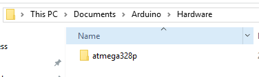
    @Samuel235 You should be able to just copy the entire folder from the .rar file into your Arduino folder. I had to create a "Hardware" folder as it didn't exist. I'm on Windows 10 and it looks like this:
    0_1486996741780_upload-d2b37622-9cf3-4539-9cb1-6f9ab39f1cf3
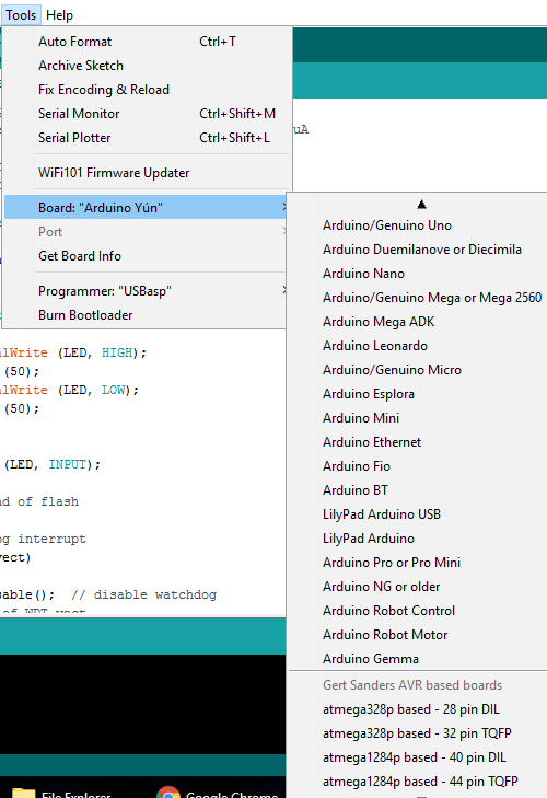
    After closing/re-opening the Arduino IDE it looks like this:
    0_1486996924662_upload-3cf12bfa-0444-4cd7-8a19-537fdf63a738


  • Hardware Contributor

    The boards .txt and platform.txt files are not complete yet, and I still need to check and change the pins_arduino.h boards for the 40 and 44 pin atmega's. That is still on my to do list, but the structure is there already. I'm still learning from other hardware deployments how to define this in a practical way. Hopefully by sharing this will be improved.


  • Hardware Contributor

    @petewill - I do that, however i do already have the hardware folder (and its a clean install of windows and arduino IDE) and then inside the hardware folder i have the boards.txt file (the default one, the list that shows in the IDE without installing gertsanders'. So, i either need to put the new one in there and rename the old or to merge the two together.

    Or am i getting this completely wrong some how?

    EDIT: It was a mistake on my own part but will leave this comment here for anyone to see and to not make the same mistake as myself:

    I was attempting to put it inside of the "arduino" folder that was inside of the hardware folder. My own fault XD


  • Hardware Contributor

    This post is deleted!

  • Hardware Contributor

    I'm slightly confused here...

    I'm using a arduino nano, hooked it up to avrdude and read the fuses as Low:FF, High:DA, Extended:05. I then burn new fuses of Low:FF, High:DE and Extended:07. Burnt fine, so i go into arduino IDE and select the bootloader for 32pin, TQFP, 8MHz external crystal 38K4 D13 and then burn bootloader. I get a little warning but that is only because of the new IDE issues with extended bits ("You probably want to use 0xfd instead of 0x05 (double check with your datasheet first)."). But now the LED on the nano is blinking rapid then stop, then blinking rapid and then stop. I can't upload a sketch to the nano either now. I can however burn the old bootloader back on and upload like normal. What could be the issue here?

    It almost seems like there is something wrong with the bootloader as it is uploading to it but the LED is blinking weirdly. May not be the bootloader itself, could just be some corruption as it gets uploaded....


  • Hardware Contributor

    @Samuel235
    If you are using a nano, what crystal is mounted on it ? Fast flashing indicates the processor is running faster then the expected 8MHz (expected by the timing routines of the bootloader). Could it be a 16MHz model ?
    In that case you could try to upload a sketch at a higher speed: 76K8 baud.
    Or you can try to load the bootloader for 16MHz/D13 (which in effect is the standard bootloader of an Arduino).


  • Hardware Contributor

    @Samuel235
    It also seems the nano is in a reset loop. I'm at work so I can not check my Mac for the fuse settings I use.


  • Hardware Contributor

    @GertSanders Soon as i say the fast flashing I instantly thought that its running quicker than needed, but i had no idea about the resetting that you have pointed out, so thanks for pointing that one out. The reason i didn't even bother trying the 16MHz settings in fuses would be that because when i read the fuses of the arduino before i did anything, it indicated that it was running with fuses of 8MHz and the blink sketch was perfectly timed on those settings.... Could it be a miss read on the fuse settings maybe? Should i read at a slower speed when using avrdude?

    The crystal is so small on the nano and i can't even see the engraving with a microscope properly either.

    I can confirm that the 16MHz bootloader is working perfectly on this nano. Thanks.


  • @GertSanders

    I have been running your bootloader for all my nodes now and that works very well.
    But there is something that surprised me. When I compile the next sketch and compare that with the Moteino bootloader it's substantially larger.

    /***************************************************************************************
    **
    ** Outdoor sensor v1.0 Measuring temperature, humdity, pressure and light level
    **  Calculating a weather forecast with the height comensated air pressure.
    **      powered by a solar panel and a 1000mAh Li-Ion battery.
    **
    ** Scraped together by D Hille. MySensors library by Henrik Ekblad et al.
    **
    **      Heat index calculation from DHT library by Adafruit
    **      MAX44009 bij Rob Tillaart
    **      Weather forecast based on AN3914 by Freescale
    **
    ****************************************************************************************/
    //                    MySensors definitions
    
    //#define MY_DEBUG                      // Enable debug prints (6 kb flash space)
    //#define MY_DEBUG_VERBOSE_SIGNING      // Comment out when no signing is used or when everything is OK (3 kb flash space)
    
    #define MY_BAUD_RATE 57600            // Set serial baudrate
    
    #define MY_RADIO_RFM69                // Enable and select radio type attached
    //#define MY_IS_RFM69HW                 // Comment out when using standard RFM69W
    
    #define MY_NODE_ID 110                 // Delete to use automatic ID assignment
    
    //#define MY_CORE_ONLY
    
    /**************************************************************************/
    //                        Transport
    /**************************************************************************/
    
    //#define MY_TRANSPORT_WAIT_READY_MS 1000 //Start the node even if no connection to the GW could be made (disable for sensor nodes).
    #define MY_TRANSPORT_STATE_RETRIES 1
    #define MY_TRANSPORT_MAX_TSM_FAILURES    (2u)
    #define MY_TRANSPORT_TIMEOUT_EXT_FAILURE_STATE (60*1000ul)
    
    
    /**************************************************************************/
    //                        Security
    /**************************************************************************/
    
    //#define MY_SIGNING_ATSHA204
    //#define MY_SIGNING_SOFT
    //#define MY_SIGNING_SOFT_RANDOMSEED_PIN 7
    //#define MY_SIGNING_REQUEST_SIGNATURES
    //#define MY_SIGNING_NODE_WHITELISTING {{.nodeId = 0,.serial = {0xD0,0xB1,0x90,0x99,0xC3,0x03,0x08,0xD1,0x34}}}
    
    //#define MY_RFM69_ENABLE_ENCRYPTION
    
    
    /**************************************************************************/
    //                    Sensor definitions
    /**************************************************************************/
    
    #define BATTERY_POWERED
    #define battUpdater 300           //Number of TX actions to count before a new battery status update is sent.
    
    #define MY_DEFAULT_TX_LED_PIN 5   // Comment out when no LED is attached.
    #define MY_WITH_LEDS_BLINKING_INVERSE
    
    #define SENSOR_TYPE 3
    // Sensor types:
    // 0.: no climate sensor attached
    // 1.: RFM69 on-die               Temperature sensor on the RFM69 module (whole integers only)
    // 2.: DS18B20                    Dallas one-wire sensor(data pin D14)
    // 3.: HTU21D                     Temp/humidity (I2C)
    // 4.: BME280                     Temp/humidity/pressure (I2C) (node will wake every minute to keep up with trend measureing)
    #define SENSOR_UPDATE 2           // Time in minutes the sensor sends an update
    
    //#define LIGHT_SENSOR_PRESENT      // Comment out when not present. (I2C) (Light sensor will update every 60 seconds.)
    
    //#define INTERRUPT_SENSOR_PRESENT  // Comment out when not present (e. g. motion sensor connect to D3)
    
    #define alti 57                  //altitude offset to compensate the barometric pressure
    
    
    /**************************************************************************/
    //                  Debug definitions
    /**************************************************************************/
    
    //#define LOCAL_DEBUG                              //Comment out to switch all debug messages off (saves 2 kb flash)
    
    #ifdef MY_DEBUG                                  //Differentiate between global debug including radio and local debug 
      #define LOCAL_DEBUG                            //for the sketch alone.
    #endif 
    
    #ifdef LOCAL_DEBUG 
      #define Sprint(a) (Serial.print(a))            // Macro as substitute for serial debug. Will be an empty macro when
      #define Sprintln(a) (Serial.println(a))        // debug is switched off
    #else
      #define Sprint(a)                                       
      #define Sprintln(a)
    #endif
    
    
    /**************************************************************************/
    
    #include <Button.h>
    #include <SPI.h>
    #include <Wire.h>
    #include <MySensors.h>
    //#include <SparkFunBME280.h>
    //#include <MAX44009.h>                           // Uncomment library used in sketch
    #include <Adafruit_HTU21DF.h>
    //#include <OneWire.h>
    //#include <DallasTemperature.h>
    #include <Vcc.h>
    
    
    #define BMEaddr 0x76
    #define Max44099Addr 0x4A
    #define sketchName "sensorNode(living)"
    #define sketchVer "1.0" 
    
    #define sensorPowerPin 20
    
    #define digitalSensorPin 14
    #define analogSensorPin A0
    #define oneWireBusPin 14
    #define interruptPin 3
    #define altSensorPin 18
    #define altAnalogPin A4
    #define sensorPowerPin 6
    
    #define chanTemp 0
    #define chanHum 1
    #define chanHeat 2 
    #define chanBaro 3
    #define chanDelta 4
    #define chanLight 5
    #define chanRate 6
    #define chanInterrupt 8
    
    #define PULLUP false
    #define INVERT false
    #define bounceTime 20
    #define sleepWait 500           //Time to wait in ms before node sleeps (to be able to receive notification messages).
    
    bool battPower = true;
    
    unsigned long currTime = 0;
    unsigned long sleepTime = (60000 * SENSOR_UPDATE);
    unsigned long lastSensorUpdate;
    unsigned long nextSensor;
    unsigned long measureTime;
    int wakeReason = -1;
    int sendLoop = 0;
    bool updated = false;
    bool ACKed = false;
    
    int sensorFunc = 0;
    float sensorData = 0.0;
    float heatTemp = 0.0;
    float heatHum = 0.0;
    bool interruptState = false;
    bool lastInterrupt = false;
    bool sensorPresent = false;
    bool lightPresent = false;
    bool interruptPresent = false;
    
    int minuteCount = 0;
    bool firstRound = true;         
    float pressureAvg;               // average value is used in forecast algorithm. 
    float pressureAvg2;              // average after 2 hours is used as reference value for the next iteration.
    float dP_dt;
    const int LAST_SAMPLES_COUNT = 5;
    float lastPressureSamples[LAST_SAMPLES_COUNT];
    
    bool startUp = true;
    bool metric = true; 
    
    int battStatCounter = 0;
    const float VccMin = 1.8;                   // Minimum expected Vcc level, in Volts.
    const float VccMax = 3.0;                   // Maximum expected Vcc level, in Volts.
    const float VccCorrection = 1.0/1.0;      // Measured Vcc by multimeter divided by reported Vcc
    
    
    /**************************************************************************/
    //                  Library declarations
    /**************************************************************************/
    
    //  Uncomment necessary declarations.
    
    //RFM69 wireless;
    
    //OneWire OWB(oneWireBusPin);
    //DallasTemperature DS18(&OWB);
    //DeviceAddress DS18address;
    
    Adafruit_HTU21DF HTU = Adafruit_HTU21DF();
    
    //BME280 BME;
    
    //Max44009 lightMax(Max44099Addr);
    
    //Button reedContact(interruptPin, PULLUP, INVERT, bounceTime);
    
    MyMessage msgHum(chanHum, V_HUM);
    MyMessage msgTemp(chanTemp, V_TEMP);
    //MyMessage msgBaro(chanBaro, V_PRESSURE);
    //MyMessage msgTrend(chanUniversal, V_VAR5);
    //MyMessage msgLight(chanLight, V_LEVEL);
    //MyMessage msgIntr(chanInterrupt, V_TRIPPED);
    
    Vcc vcc(VccCorrection);
    
    /**************************************************************************/
    //                  Error messages
    /**************************************************************************/
    
      #if (defined INTERRUPT_SENSOR_PRESENT && defined LIGHT_SENSOR_PRESENT && SENSOR_TYPE >= 4)
        #error Motion sensor can anly be combined with either I2C OR one-wire sensors, not both.
      #endif
    
      #if (defined INTERRUPT_SENSOR_PRESENT && (defined LIGHT_SENSOR_PRESENT || SENSOR_TYPE == 4) && defined BATTERY_POWERED)
        #error Interrupt sensor is not compatible with trend sensors like 'baro' and 'light' because the timer will misalign.
      #endif
    
      #if (SENSOR_TYPE > 4)
        #error Not a valid sensor type!
      #endif
    
    
    /**************************************************************************/
    
    void before(void)
    {  
      Serial.println("\nReading config...");
    
      #ifndef BATTERY_POWERED
        battPower = false;
      #endif
    
      sensorFunc = SENSOR_TYPE;
    
      #ifdef LIGHT_SENSOR_PRESENT
        lightPresent = true;
      #endif
    
      #ifdef INTERRUPT_SENSOR_PRESENT
        interruptPresent = true;
        lastInterrupt = reedContact.read();
      #endif
    
      #if (defined MY_SIGNING_SOFT || defined MY_SIGNING_ATSHA204)
        #define sendPause 100
      #else
        #define sendPause 50
      #endif
    }
     
    /**************************************************************************/
    
    void setup(void)
    {  
      pinMode(sensorPowerPin, OUTPUT);       //switch on the sensor power
      digitalWrite(sensorPowerPin, HIGH);    
      wait(50);                              //wait 50 ms for the sensors to settle.
      
      switch (sensorFunc) {
        case 0:
        break;
        case 1:
          sensorPresent = true;
        break;
        case 2: 
          //DS18.begin();
          //DS18.getAddress(DS18address, 0);
          //DS18.setResolution(DS18address, 10);
          sensorPresent = true;
        break;
        case 3:
          HTU.begin();
          sensorPresent = true;
        break;
        case 4:
          //startBME();
          sleepTime = 60000;
          sensorPresent = true;
        break;    
      }
    
      #if (lightPresent)
        sleepTime = 60000;
        sensorPresent = true;
      #endif
    
      #ifdef MY_DEBUG                //Differentiate between global debug including radio and local debug          
        sleepTime = 30000;              //for the sketch alone.
      #endif
    
      batteryStats();
    
      Serial.println("\nDone. \n\nStarting program.\n");
      
      currTime = millis();
    }
    
    /**************************************************************************/
    
    void presentation()  
    {
      Serial.println("Start radio and sensors");  
      
      sendSketchInfo(sketchName, sketchVer);
    
      Sprint("\nPresent ");  
      
      if (sensorFunc >= 1) {
        wait(sendPause);
        present(chanTemp, S_TEMP, "Climate", true);
        Sprint("temperature");
      }
      if (sensorFunc >= 3) {
        wait(sendPause);
        present(chanHum, S_HUM);
        Sprint(", humidity");
        //wait(sendPause);
        //present(chanHeat ,S_TEMP);
        //Sprint(", heatindex");
      }
      if (sensorFunc == 4) {
        wait(sendPause);
        present(chanBaro, S_BARO);
        Sprint(", barometric");
        wait(sendPause);
        present(chanDelta, S_CUSTOM);
        Sprint(" and rate");
      }
      Sprintln(" sensor.");
      
      if (lightPresent) {
        wait(sendPause);   
        present(chanLight, S_LIGHT_LEVEL, "Light", true);
        Sprintln("\nLightsensor "); 
        if (sensorFunc < 4) {
          wait(sendPause);   
          present(chanRate, S_CUSTOM);
          Sprintln("with rate ");
        }
        Sprintln("presented.");     
      }
    
      if (interruptPresent) {
        wait(sendPause);
        present(chanInterrupt, S_MOTION, "Motion", true);
        Sprintln("Interrupt sensor presented.");
      }
    
      wait(sendPause);
    }
    
    
    /**************************************************************************/
    
    void loop(void)
    {
      if (wakeReason < 0) { 
        Serial.println("Reading sensors...");
        switch (sensorFunc) {
          case 0:
          break;
          case 1:
            updateRFM();
          break;
          case 2:
            updateDS18();
          break;
          case 3:
            updateHTU();
          break;  
          case 4:
            if (sendLoop <= 0) {
              updateBME();
              updated = true;
            }  
            else {
              Sprint("\nTrend: ");
              updateTrend();
              sendLoop--;
            }
          break;
        }
        if (lightPresent) {
          updateMAX();
          if (sensorFunc <= 3) {
            Sprint("\nTrend: ");
            updateTrend();
          }
        }
        wakeReason = 0;
        Sprintln("\nSensors updated...");
      }
      else if (wakeReason == 1) {
        updateInterrupt();
        wakeReason = 0;
      }
      
      if (battStatCounter >= battUpdater) {  
        batteryStats();
      }
      
      if (updated) {
        sendLoop = SENSOR_UPDATE;
        updated = false;
      }
      
      if (millis() >= currTime + sleepWait) {
        startUp = false;
        sleepSensor();
      }
    }
    
    
    /**************************************************************************/
    
    void updateInterrupt()
    {/*
      Sprintln("\nInterrupt: ");
      interruptState = reedContact.read();
      wait(50);
      if (interruptState == !lastInterrupt) {
        send(msgIntr.setSensor(chanInterrupt).set(interruptState),true);
        lastInterrupt = interruptState;
      }
      
      Sprint("Door/window is ");
      if (interruptState) {
        Sprintln("opened.");
      }
      else {
        Sprintln("closed");
      }*/
    }
    
    
    /**************************************************************************/
    
    void updateRFM()
    {/*
      Sprintln("\nRFM: ");
      sensorData = wireless.readTemperature();
      wait(20);
      send(msgTemp.set(sensorData, 0));
      Sprint("Temperature: \t"); Sprint(sensorData); Sprintln(" sent.");
      battStatCounter++;*/
    }
    
    /**************************************************************************/
    
    void updateDS18()
    {/*
      Sprintln("\nOne-wire: ");
      DS18.requestTemperatures();
      sensorData = DS18.getTempCByIndex(0);
      wait(20);
      send(msgTemp.set(sensorData, 2));
      battStatCounter++;
      Sprint("Temperature: "); Sprint(sensorData); Sprintln(" sent.");*/
    }
    
    
    /**************************************************************************/
    
    void updateHTU()
    {
      Sprintln("\nHTU: ");
      sensorData = HTU.readTemperature();
      heatTemp = sensorData;
      wait(20);
      send(msgTemp.set(sensorData, 1));
      Sprint("Temperature: \t"); Sprint(sensorData); Sprintln(" sent.");
      sensorData = HTU.readHumidity();
      heatHum = sensorData;
      wait(sendPause);
      send(msgHum.set(sensorData, 1));
      Sprint("Humidity: \t"); Sprint(sensorData); Sprintln(" sent.");
      //wait(sendPause);
      //send(msgHeat.set(computeHeatIndex(heatTemp, heatHum), 1));
      //Sprint("Heatindex sent.");  
      battStatCounter++;
    }
    
    
    /**************************************************************************/
    
    void updateBME()
    {
      /*Sprintln("\nBME: ");
      BME.begin();
      wait(100);
      sensorData = (BME.readFloatPressure()/pow(1-(alti/44330.0),5.255)/100);
      if (!startUp) {
        trend(sensorData);
        send(msgBaro.set(sensorData,1));
        Sprint("Pressure: \t"); Sprint(sensorData); Sprintln(" sent.");
      }
      if (!(minuteCount < 35 && firstRound)) {
        wait(sendPause);
        send(msgTrend.set(dP_dt,2));
        Sprint("Trend: \t\t"); Sprint(dP_dt); Sprintln(" sent.");
      }
      wait(sendPause);  
      sensorData = BME.readTempC();
      heatTemp = sensorData;
      send(msgTemp.set(sensorData,1));
      Sprint("Temperature: \t"); Sprint(sensorData); Sprintln(" sent.");
      wait(sendPause);
      sensorData = BME.readFloatHumidity();
      heatHum = sensorData;
      send(msgHum.set(sensorData,1));
      Sprint("Humidity: \t"); Sprint(sensorData); Sprintln(" sent.");
      wait(sendPause);
      send(msgHeat.set(computeHeatIndex(heatTemp, heatHum), 1));
      Sprint("Heatindex sent.");
      battStatCounter++;*/
    }
    
    
    /**************************************************************************/
    
    float computeHeatIndex(float tempInput, float humInput)       //Function derived from Adafruit DHT library
    {
      /*// Using both Rothfusz and Steadman's equations
      // http://www.wpc.ncep.noaa.gov/html/heatindex_equation.shtml
      float hiFar;
    
      float tempFar = tempInput * 1.8 + 32;
    
      hiFar = 0.5 * (tempFar + 61.0 + ((tempFar - 68.0) * 1.2) + (humInput * 0.094));
    
      if (hiFar > 79) {
        hiFar = -42.379 +
                 2.04901523 * tempFar +
                10.14333127 * humInput +
                -0.22475541 * tempFar*humInput +
                -0.00683783 * pow(tempFar, 2) +
                -0.05481717 * pow(humInput, 2) +
                 0.00122874 * pow(tempFar, 2) * humInput +
                 0.00085282 * tempFar*pow(humInput, 2) +
                -0.00000199 * pow(tempFar, 2) * pow(humInput, 2);
    
        if((humInput < 13) && (tempFar >= 80.0) && (tempFar <= 112.0))
          hiFar -= ((13.0 - humInput) * 0.25) * sqrt((17.0 - abs(tempFar - 95.0)) * 0.05882);
    
        else if((humInput > 85.0) && (tempFar >= 80.0) && (tempFar <= 87.0))
          hiFar += ((humInput - 85.0) * 0.1) * ((87.0 - tempFar) * 0.2);
      }
    
      return (hiFar - 32) * 0.55555;*/
    }
    
    
    /**************************************************************************/
    void updateTrend()
    {
      /*if (sensorFunc == 4) {
       * Sprint("BME -> ");
        BME.begin();
        wait(100);
        sensorData = (BME.readFloatPressure()/pow(1-(alti/44330.0),5.255)/100);
      }
      else if (lightPresent) {
        Sprint("MAX -> ");
        sensorData = lightMax.getLux();
      }
      trend(sensorData);*/
    }
    
    
    /**************************************************************************/
    
    void updateMAX()
    {
      /*Sprintln("\nLight: ");
      sensorData = lightMax.getLux();
      if (sensorFunc <= 3) {
        trend(sensorData);
      }
      send(msgLight.set(sensorData,1));
      Sprint("Light: \t"); Sprint(sensorData); Sprintln(" sent.");
      if (sensorFunc <= 3) {
        if (!(minuteCount < 35 && firstRound)) {
          wait(sendPause);
          send(msgTrend.set(dP_dt,2));
          Sprint("Trend: \t"); Sprint(dP_dt); Sprintln(" sent.");
        }
      }
      battStatCounter++;*/
    }
    
    
    /**************************************************************************/
    
    void sleepSensor()
    {
      if (battPower) {
        Serial.println("\nSleep the sensor.");
        wait(50); 
        unsigned long lightsOut = (sleepTime - (millis() - currTime));
        if (interruptPresent) {
          if (sensorPresent) {
            wakeReason = sleep(1, CHANGE, lightsOut);
          }
          else {
            wakeReason = sleep(1, CHANGE, 0);
          }
        }
        else {
          //digitalWrite(sensorPowerPin, LOW);      //Disabled because of the I2C pull ups on the HTU board
          sleep(lightsOut);                         //causing a 140uA load in sleep. Without, sleep drain is 5uA.
          wakeReason = -1;
          //digitalWrite(sensorPowerPin, HIGH);
          wait(50);
        }
        currTime = millis();
        Sprint("Wake reason: ");Sprintln(wakeReason);
      }
      else if (millis() >= currTime + sleepTime) {
        wakeReason = -1;
        currTime = millis();
      }
    }
    
    
    /**************************************************************************/
    
    /*void startBME()
    {
      BME.settings.commInterface = I2C_MODE;
      BME.settings.I2CAddress = BMEaddr;
      BME.settings.runMode = 1;            //  1, Single mode
      BME.settings.tStandby = 0;           //  0, 0.5ms
      BME.settings.filter = 0;             //  0, filter off
      BME.settings.tempOverSample = 1;
      BME.settings.pressOverSample = 1;
      BME.settings.humidOverSample = 1;  
      
      BME.begin();
    }
    
    
    /**************************************************************************/
    
    float getLastPressureSamplesAverage()
    {
      float lastPressureSamplesAverage = 0;
      for (int i = 0; i < LAST_SAMPLES_COUNT; i++)
      {
        lastPressureSamplesAverage += lastPressureSamples[i];
      }
      lastPressureSamplesAverage /= LAST_SAMPLES_COUNT;
    
      return lastPressureSamplesAverage;
    }
    
    
    /**************************************************************************/
    
    void trend(float pressure)
    {/*
      int index = minuteCount % LAST_SAMPLES_COUNT;                 // Calculate the average of the last 5 minutes.
      lastPressureSamples[index] = pressure;
    
      minuteCount++;
      if (minuteCount > 185)
      {
        minuteCount = 6;
      }
    
      if (minuteCount == 5)
      {
        pressureAvg = getLastPressureSamplesAverage();
        Sprint("First average: "); Sprint(pressureAvg);
      }
      else if (minuteCount == 35)
      {
        float lastPressureAvg = getLastPressureSamplesAverage();
        float change = (lastPressureAvg - pressureAvg);
        if (firstRound)                                             // first time initial 3 hour
        {
          dP_dt = change * 2;                                       // note this is for t = 0.5hour
        }
        else
        {
          dP_dt = change / 1.5;                                     // divide by 1.5 as this is the difference in time from 0 value.
        }
      }
      else if (minuteCount == 65)
      {
        float lastPressureAvg = getLastPressureSamplesAverage();
        float change = (lastPressureAvg - pressureAvg);
        if (firstRound)                                             //first time initial 3 hour
        {
          dP_dt = change;                                           //note this is for t = 1 hour
        }
        else
        {
          dP_dt = change / 2;                                       //divide by 2 as this is the difference in time from 0 value
        }
      }
      else if (minuteCount == 95)
      {
        float lastPressureAvg = getLastPressureSamplesAverage();
        float change = (lastPressureAvg - pressureAvg);
        if (firstRound)                                             // first time initial 3 hour
        {
          dP_dt = change / 1.5;                                     // note this is for t = 1.5 hour
        }
        else
        {
          dP_dt = change / 2.5;                                     // divide by 2.5 as this is the difference in time from 0 value
        }
      }
      else if (minuteCount == 125)
      {
        float lastPressureAvg = getLastPressureSamplesAverage();
        pressureAvg2 = lastPressureAvg;                             // store for later use.
        float change = (lastPressureAvg - pressureAvg);
        if (firstRound)                                             // first time initial 3 hour
        {
          dP_dt = change / 2;                                       // note this is for t = 2 hour
        }
        else
        {
          dP_dt = change / 3;                                       // divide by 3 as this is the difference in time from 0 value
        }
      }
      else if (minuteCount == 155)
      {
        float lastPressureAvg = getLastPressureSamplesAverage();
        float change = (lastPressureAvg - pressureAvg);
        if (firstRound)                                             // first time initial 3 hour
        {
          dP_dt = change / 2.5;                                     // note this is for t = 2.5 hour
        }
        else
        {
          dP_dt = change / 3.5;                                     // divide by 3.5 as this is the difference in time from 0 value
        }
      }
      else if (minuteCount == 185)
      {
        float lastPressureAvg = getLastPressureSamplesAverage();
        float change = (lastPressureAvg - pressureAvg);
        if (firstRound)                                             // first time initial 3 hour
        {
          dP_dt = change / 3;                                       // note this is for t = 3 hour
        }
        else
        {
          dP_dt = change / 4;                                       // divide by 4 as this is the difference in time from 0 value
        }
        pressureAvg = pressureAvg2;                                 // Equating the pressure at 0 to the pressure at 2 hour after 3 hours have past.
        firstRound = false;                                         // flag to let you know that this is on the past 3 hour mark. Initialized to 0 outside main loop.
      }
    
      Sprint(F("\tForecast at minute "));
      Sprint(minuteCount);
      Sprint(F(" dP/dt = "));
      Sprint(dP_dt);
      Sprint(F("hPa/h --> "));*/
    }
    
    
    /**************************************************************************/
    
    void batteryStats()
    {
      if (battPower) {
        float battPct = vcc.Read_Perc();
        float battVolt = vcc.Read_Volts();
        wait(50);
        sendBatteryLevel(battPct);
        Sprint("Battery level: "); Sprint(battVolt); Sprintln("V.\n");
        battStatCounter = 0;
        wait(50);
      }  
    }
    
    
    /**************************************************************************/
    
    void sendBattLevel()
    {
      /*Serial.println("\nBattery: ");
      int ADread = analogRead(batteryPin);
      int battPcnt = map(ADread, 570, 704, 0, 100);  //Usable voltage range from 3.4 to 4.2V
      battPcnt = constrain(battPcnt, 0, 100);        //Charging keeps it at 100%
      sendBatteryLevel(battPcnt);
      Sprint("\nADread\t"); Sprint(ADread); Sprint("\t"); Sprintln(battPcnt);
      battStatCounter = 0;*/
    }  
    

    GertSanders ATMega328p 32p TFQP, 8MHz, 38400baud

    Warning: Board breadboard:avr:atmega328bb doesn't define a 'build.board' preference. Auto-set to: AVR_ATMEGA328BB
    
    Sketch uses 16,680 bytes (51%) of program storage space. Maximum is 32,256 bytes.
    Global variables use 942 bytes (45%) of dynamic memory, leaving 1,106 bytes for local variables. Maximum is 2,048 bytes.
    

    LowPowerLab Moteino 16MHz

    Warning: Board breadboard:avr:atmega328bb doesn't define a 'build.board' preference. Auto-set to: AVR_ATMEGA328BB
    
    Sketch uses 14,264 bytes (44%) of program storage space. Maximum is 31,744 bytes.
    Global variables use 890 bytes of dynamic memory.
    

    In this sketch the size difference doesn't matter that much. But when I introduce signing it will get tight.
    Any thoughts?

    (This is a standard sketch which I adapt for every node by commenting out the parts I do not need. So it might seem large for a simple temperature node. It is...).


  • Hardware Contributor

    @DavidZH
    Do you also get these differences when compiling for both 16Mhz ? In this case one node is 16MHz (Moteino) and the second is 8MHz.
    Apart from that I have no clue why this would result in different sizes.


  • I have tried with your bootloader on 16MHz and 8 MHz with crystal.

    8MHz, crystal, 1V8

    Warning: Board breadboard:avr:atmega328bb doesn't define a 'build.board' preference. Auto-set to: AVR_ATMEGA328BB
    Build options changed, rebuilding all
    
    Sketch uses 16,680 bytes (51%) of program storage space. Maximum is 32,256 bytes.
    Global variables use 942 bytes (45%) of dynamic memory, leaving 1,106 bytes for local variables. Maximum is 2,048 bytes.
    

    16MHz, crystal, 1V8

    Warning: Board breadboard:avr:atmega328bb doesn't define a 'build.board' preference. Auto-set to: AVR_ATMEGA328BB
    Build options changed, rebuilding all
    
    Sketch uses 16,694 bytes (51%) of program storage space. Maximum is 32,256 bytes.
    Global variables use 942 bytes (45%) of dynamic memory, leaving 1,106 bytes for local variables. Maximum is 2,048 bytes. 
    

    So the 16Mhz file is actally even a bit bigger. I also tried if changing the BOD voltage would change anything, but nope on that.

    Might be something to look into in a spare hour.


  • hy,
    can anyone tell me what is the word near cpu 8mhz-38k4-d13 etc..??
    tanks


  • Hardware Contributor

    @mar.conte - Your question isn't very clear. If you're asking what the name means its broken down as:

    8mhz - Crystal speed/frequency
    38k4 - 38400 upload speed
    D13 - Pin 13 to flash the LED (if needed) just for visual indication that the bootloader has been burnt/installed.

    Not sure if that is what you meant but I could only assume. If not then please attempt to explain a little clearly for us 🙂

    Hope that sorts your problem!


  • @Samuel235
    Sorry for my english, your answer is ok Tanks you


  • Hardware Contributor

    @mar.conte - Its okay, i understood you, just about 😉

    Now just apply that description to all of the other bootloader varients that the great @Gertsanders has provided us with 🙂


  • Help!!!
    I have upload bootloader 8mhz 38k bod 2,7 and internal clock with sketch j gammon!!!
    Consumption 2 mh!!!
    Why?
    Tanks


  • Hardware Contributor

    I'm sorry, i don't understand the issue at hand.... Could you attempt to explain any clearer?


  • This post is deleted!


  • @Samuel235
    Hy
    My project is simple atmega328 with internal clock 8 mhz in powerdown mode end rfm69 hw which send to gateway when pir motion is high powered all with 2 aa battery.
    The First test what i do is in breadboard atmega328 with optiboot 6.2 ( i have upload bootloader 8mhz internal , 38vk, bod 2v7) and simple sketch j gammon: result no microampere but around 2/5 mah in sleep mode;


  • @mar.conte I'm not familiar with the sketch you mentioned. The best is to use the voltmeter and oscillograph to determine consumption.

    Why do you have BOD 2.7v? I do not have any BOD - this would let a node to run on two batteries until voltage drops to below 1.9V


  • @alexsh1
    I have only voltmeter extec, can i mesure ua?
    Can you send simple sketch for deep sleep ?


  • Hardware Contributor

    @mar.conte - Are you basically saying that your hardware is using too much power to enable you to run on battery for any substantial time?


  • @Samuel235
    Yes, i want obtain few micro amp but its two month wich i try without result.....


  • Hardware Contributor

    @mar.conte Which skecth did you use ?
    Did you have radio errors in your log ?


  • Hardware Contributor

    Could you please either include your sketch here or give us a link to the example sketch that you used please.


  • @Samuel235
    Resolved
    I have try with sketc j gammon https://www.gammon.com.au/forum/?id=11497
    And the problem are pir input (model hrc-501)
    Are ever high and the cpu dont go in sleep.
    I have remove pir and all ok the atmega run 20 uah very good.
    Can you advise a good pir wich run to 3,3 V for my project?
    Tanks


  • @mar.conte
    im not sure why pir with simple test like this http://playground.arduino.cc/Code/PIRsense is ok
    but with my sketch the cpu reset forever

    
    #include <Arduino.h>            // assumes Arduino IDE v1.0 or greater
    #include <avr/sleep.h>
    #include <avr/wdt.h>
    #include <avr/power.h>
    #include <avr/io.h>


    ISR (PCINT2_vect)
    {
      // handle pin change interrupt for D0 to D7 here
    }  // end of PCINT2_vect


    const unsigned long WAIT_TIME = 4000;
    
    
     const byte  LED =8 ;
     
     const byte  LED2 =9 ;
    int  wakepin =3 ;
      unsigned long lastSleep;


    volatile boolean motionDetected=false;
    float batteryVolts = 5;
    char BATstr[10]; //longest battery voltage reading message = 9chars
    char sendBuf[32];
    byte sendLen;
    void checkBattery(void);
    
    #include <RFM69.h>    //get it here: https://www.github.com/lowpowerlab/rfm69
    #include <SPI.h>
    
    //*********************************************************************************************
    // *********** IMPORTANT SETTINGS - YOU MUST CHANGE/ONFIGURE TO FIT YOUR HARDWARE *************
    //*********************************************************************************************
    #define NETWORKID     100  // The same on all nodes that talk to each other
    #define NODEID        2    // The unique identifier of this node
    #define RECEIVER      1    // The recipient of packets
    
    //Match frequency to the hardware version of the radio on your Feather
    //#define FREQUENCY     RF69_433MHZ
    //#define FREQUENCY     RF69_868MHZ
    #define FREQUENCY     RF69_868MHZ
    #define ENCRYPTKEY    "sampleEncryptKey" //exactly the same 16 characters/bytes on all nodes!
    #define IS_RFM69HW   true // set to 'true' if you are using an RFM69HCW module
    
    //*********************************************************************************************
    #define SERIAL_BAUD   115200
    
    #define RFM69_CS      10
    #define RFM69_IRQ     2
    #define RFM69_IRQN    0  // Pin 2 is IRQ 0!
    #define RFM69_RST     9


    int16_t packetnum = 0;  // packet counter, we increment per xmission
    
    RFM69 radio = RFM69(RFM69_CS, RFM69_IRQ, IS_RFM69HW, RFM69_IRQN);  
    
    void setup () {


      pinMode (wakepin,INPUT);
        pinMode(LED, OUTPUT);
         pinMode(LED2, OUTPUT);
           digitalWrite(wakepin,HIGH);
       
      
      char buff[50];
     
      Serial.begin(SERIAL_BAUD);
    
      Serial.println("Arduino RFM69HCW Transmitter");
      
      // Hard Reset the RFM module
      pinMode(RFM69_RST, OUTPUT);
      digitalWrite(RFM69_RST, HIGH);
      delay(100);
      digitalWrite(RFM69_RST, LOW);
      delay(100);
    
      // Initialize radio
      radio.initialize(FREQUENCY,NODEID,NETWORKID);
      if (IS_RFM69HW) {
        radio.setHighPower();    // Only for RFM69HCW & HW!
      }
      radio.setPowerLevel(31); // power output ranges from 0 (5dBm) to 31 (20dBm)
      
      radio.encrypt(ENCRYPTKEY);
      
      pinMode(LED, OUTPUT);
      Serial.print("\nTransmitting at ");
      Serial.print(FREQUENCY==RF69_433MHZ ? 433 : FREQUENCY==RF69_868MHZ ? 868 : 915);
      Serial.println(" MHz");
    
     }


    uint16_t batteryReportCycles=0;


    void loop () 
    { 
        
       //rf();
    
    
      sleepNow();
       rf();
        
     //radio.sleep();
       
                    // sleep function called here 
    
    
     radio.sleep();
    }


    void wake ()
    {
    
     // cancel sleep as a precaution
      //sleep_disable();
      // precautionary while we do other stuff
     detachInterrupt (1);
    }  // end of wake
    
    void sleepNow()
    
    {
    
       if (millis () - lastSleep >= WAIT_TIME)
      {
        lastSleep = millis ();
    
    
        byte old_ADCSRA = ADCSRA;
        // disable ADC
        ADCSRA = 0;  
        // pin change interrupt (example for D0)
        PCMSK2 |= bit (PCINT16); // want pin 0
        PCIFR  |= bit (PCIF2);   // clear any outstanding interrupts
        PCICR  |= bit (PCIE2);   // enable pin change interrupts for D0 to D7
    
        set_sleep_mode (SLEEP_MODE_PWR_DOWN);
      
        power_adc_disable();
        power_spi_disable();
        power_timer0_disable();
        power_timer1_disable();
        power_timer2_disable();
        power_twi_disable();
      //PORTB = 0x00;
        UCSR0B &= ~bit (RXEN0);  // disable receiver
        UCSR0B &= ~bit (TXEN0);  // disable transmitter
    
        sleep_enable();
        
        noInterrupts ();
      attachInterrupt (1, wake,HIGH);
        digitalWrite (LED, LOW);
     
      interrupts ();
        sleep_cpu ();      
       digitalWrite (LED, HIGH);
    
        sleep_disable();
        power_all_enable();
     
        ADCSRA = old_ADCSRA;
        PCICR  &= ~bit (PCIE2);   // disable pin change interrupts for D0 to D7
        UCSR0B |= bit (RXEN0);  // enable receiver
        UCSR0B |= bit (TXEN0);  // enable transmitter
    
      }  // end of time to sleep
       
     
    }
    
    void rf()
    {
     char radiopacket[20] = "Hello World #";
      itoa(packetnum++, radiopacket+13, 10);
      Serial.print("Sending "); Serial.println(radiopacket);
        
      if (!radio.sendWithRetry(RECEIVER, radiopacket, strlen(radiopacket))) { //target node Id, message as string or byte array, message length
        Serial.println("OK");
    
      }
    
      radio.receiveDone(); //put radio in RX mode
      Serial.flush(); //make sure all serial data is clocked out before sleeping the MCU


     }
    

  • Hardware Contributor

    Firstly, i can't read the structure the way you have posted your sketch. You should use the code function in the reply, the icon looks like "</>" above where you make your reply. Put your code in there for us to have any chance of reading it at all.

    Secondly, I don't think that this is the place to be posting this issue. For a start, this isn't an issue relevant to the bootloader in this thread and secondly, it doesn't even have anything to do with MySensors.


  • @mar.conte yes, you can measure consumption (should be in uA) while sleeping with a good voltmeter.

    However, I really fail to understand what has Nick's sketch you mentioned to do with MySensors? I suppose some people here may be aware of sleeping issues, but again your problem has nothing to do with MySensors.

    Please see the following - it may help you troubleshoot your issue
    https://www.mysensors.org/build/battery


  • @Samuel235
    I wanted to build my projects with mysensors, first of all I started with bootloader found in this section to try them with examples that I know because I do not know yet mysensors, I wanted to learn it so I took the liberty to insert code in your section. if you can figure out my problem thank you or I apologize for the trouble thanks


  • Hardware Contributor

    I get why you done it, but i don't understand why. You don't need to 'know' mysensors.... There is a getting started page, i suggest you take a few hours and read through everything. I'm not helping with an issue that is completely not related to mysensors while on the mysensors forum. Just simply for future readers of this thread that come here to solve their issue, if this thread is bloated out with over 10/20 replies that is not related to the question at hand its much harder for them to find their resolution here. I suggest contacting the author of the code himself as i'm pretty sure that your issue is not the bootloader.


  • @Samuel235

    Thanks anyway, this section introduced me to some very interesting bootloader, at least with these bootloader I can get a few microamperes for my projects, I will take note of your good day and thank you tips


  • Hi guys,

    I am getting an errror when trying to burn the bootloader, any idea what´s wrong? Im using Arduino IDE 1.6.10 and these settings:
    0_1495966865551_upload-48973443-91a2-4504-a73b-96557383d6bf

    and that´s the error:

    avrdude: Version 6.3, compiled on Jun 22 2016 at 16:05:21
             Copyright (c) 2000-2005 Brian Dean, http://www.bdmicro.com/
             Copyright (c) 2007-2014 Joerg Wunsch
    
             System wide configuration file is "T:\Programme\Arduino 1.6.10\hardware\tools\avr/etc/avrdude.conf"
    
             Using Port                    : COM10
             Using Programmer              : stk500v1
             Overriding Baud Rate          : 19200
             AVR Part                      : ATmega328P
             Chip Erase delay              : 9000 us
             PAGEL                         : PD7
             BS2                           : PC2
             RESET disposition             : dedicated
             RETRY pulse                   : SCK
             serial program mode           : yes
             parallel program mode         : yes
             Timeout                       : 200
             StabDelay                     : 100
             CmdexeDelay                   : 25
             SyncLoops                     : 32
             ByteDelay                     : 0
             PollIndex                     : 3
             PollValue                     : 0x53
             Memory Detail                 :
    
                                      Block Poll               Page                       Polled
               Memory Type Mode Delay Size  Indx Paged  Size   Size #Pages MinW  MaxW   ReadBack
               ----------- ---- ----- ----- ---- ------ ------ ---- ------ ----- ----- ---------
               eeprom        65    20     4    0 no       1024    4      0  3600  3600 0xff 0xff
               flash         65     6   128    0 yes     32768  128    256  4500  4500 0xff 0xff
               lfuse          0     0     0    0 no          1    0      0  4500  4500 0x00 0x00
               hfuse          0     0     0    0 no          1    0      0  4500  4500 0x00 0x00
               efuse          0     0     0    0 no          1    0      0  4500  4500 0x00 0x00
               lock           0     0     0    0 no          1    0      0  4500  4500 0x00 0x00
               calibration    0     0     0    0 no          1    0      0     0     0 0x00 0x00
               signature      0     0     0    0 no          3    0      0     0     0 0x00 0x00
    
             Programmer Type : STK500
             Description     : Atmel STK500 Version 1.x firmware
             Hardware Version: 2
             Firmware Version: 1.18
             Topcard         : Unknown
             Vtarget         : 0.0 V
             Varef           : 0.0 V
             Oscillator      : Off
             SCK period      : 0.1 us
    
    avrdude: AVR device initialized and ready to accept instructions
    
    Reading | ################################################## | 100% 0.06s
    
    avrdude: Device signature = 0x1e950f (probably m328p)
    avrdude: erasing chip
    avrdude: reading input file "0x3F"
    avrdude: writing lock (1 bytes):
    
    Writing | ################################################## | 100% 0.03s
    
    avrdude: 1 bytes of lock written
    avrdude: verifying lock memory against 0x3F:
    avrdude: load data lock data from input file 0x3F:
    avrdude: input file 0x3F contains 1 bytes
    avrdude: reading on-chip lock data:
    
    Reading | ################################################## | 100% 0.02s
    
    avrdude: verifying ...
    avrdude: 1 bytes of lock verified
    avrdude: reading input file "0x06"
    avrdude: writing efuse (1 bytes):
    
    Writing |  ***failed;  
    ################################################## | 100% 0.16s
    
    avrdude: 1 bytes of efuse written
    avrdude: verifying efuse memory against 0x06:
    avrdude: load data efuse data from input file 0x06:
    avrdude: input file 0x06 contains 1 bytes
    avrdude: reading on-chip efuse data:
    
    Fehler beim Brennen des Bootloaders.
    Reading | ################################################## | 100% 0.02s
    
    avrdude: verifying ...
    avrdude: verification error, first mismatch at byte 0x0000
             0xfe != 0x06
    avrdude: verification error; content mismatch
    
    avrdude done.  Thank you.


  • @siod what board are you using? Windows or Mac?
    I would suggest update Arduino IDE - you are running an old version

    Many people experience similar issues when using a wrong version of IDE:

    https://forum.arduino.cc/index.php?topic=431294.0


  • Hardware Contributor

    I have been using version 1.8.x (at 1.8.2 now) for quite a while now, so no experience with 1.6.10

    Best is indeed to update the IDE, as this will also bring new versions of GCC (the compiler) and I thought also of AVRDUDE (transfertool). Not sure about that last bit though.

    Gert


  • Hi guys,

    thx for your quick reply. I could upload the bootloader using ver 1.6.5 of the Arduino IDE. After that I realized ther is already a 1.8.2 version released which is closing the gaps between arduino.cc and arduino.org.
    I havent tested this version now, but I guess it was just an IDE error, so everything´s fine now...


  • I have copy the file over the existing files and then I get this error with burning:

    java.io.IOException: Cannot run program "{runtime.tools.avrdude.path}/bin/avrdude": CreateProcess error=2, The system cannot find the file specified

    I am using Arduino IDE 1.8.2


  • I'm probably a rare case but I successfully burn the bootloader (atmel 328p stand alone with slimeNode board) using atmel studio7 with an AVRMK2ISP, flash the mySensors code using arduino IDE and the "nodeManager" libraries succesfully too and everythings appear properly in my HomeAssistant, very nice, I've just give a paypal tips ;o)

    But I have no idea why I use this bootloader ??? If I used a nano, I wont change the bootloader ? Is there something better ? It could look stupid but their is no real explain about WHY I must change my bootloader on this page...


  • Found these bootloaders and using the 1MHz for some low power experiments. I did get this error message when burning the bootloader (using USBASP programmer) :
    "avrdude: WARNING: invalid value for unused bits in fuse "efuse", should be set to 1 according to datasheet
    This behaviour is deprecated and will result in an error in future version
    You probably want to use 0xfd instead of 0x05 (double check with your datasheet first)."

    The bootloader woas succesfully burned so the message was informational. I did look into this and made the following changes in boards.txt :
    I changed all the lines containing "......bootloader.extended_fuses="
    There are multiples sections in the file that have these lines.

    old value -> new value
    0x04 0xFC
    0x05 0xFD
    0x06 0xFE
    0x07 0xFF

    I used this site link text
    for calculating the new values for the extended fuse.
    Now the error message is gone. Maybe this is of any help when using these bootloaders.


  • Banned

    This post is deleted!

Log in to reply
 

Suggested Topics

25
Online

11.2k
Users

11.1k
Topics

112.5k
Posts