Homini Complete Room Sensor Module?
-
I'm encountering some issues regarding my MOSFET enabled PIR sensor. I'm currently using a n-channel MOSFET in a high side switching setup. The issues that i'm getting are that while the gate is pulled low, the sensor is alternating between a HIGH and LOW output, false triggering and when the gate is 5v, high, it is not powering at all.
I'm attempting to get my hands on a p-channel MOSFET to put in a low side switching application to attempt to fix this. I'm assuming that its acting like this because its producing false triggers while the GND is not connected through to ground. I've tried to connect a 10k resistor from drain to gate to eradicate the 'floating' connection, no hope either. If anyone has a link to any p-channel MOSFET that i can get in the UK that would be much appreciated.
-
There is currently discussions going on over on the forums at allaboutcircuits.com with myself and a few others regarding this OP AMP and the sensor output readings. I thought i would let you guys know in case you're interested in following the build.
-
Once i have the smoke detection worked out and the carbon monoxide circuit more 'suited' i feel we're on the straight and narrow. Adding in things like signing, EEPROM, headers, temp sensors, is all easy and no configuration on the hardware level is needed. So over the next week or two i will be working to get the two sensors correctly working and optimized to the best suited adaptions with this device, then its a case of adding in any functionality that we feel is needed. I would like some feedback from you guys with what features you feel are appropriate for this module, EEPROM, Flash, signal LEDs, security signing, anything at all!
-
UPDATE!
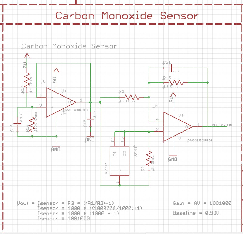
The sensor circuitry is now complete to give me a baseline voltage of 0.93V. This will allow for any variation in the sensor and the offset created by the op amp. I have used a double op amp system, the second op amp is performing a voltage follower role to remove any current interference from the voltage divider i have put in place to create the baseline to allow for errors to occur. The below schematic is for this section of the module. Getting close to getting the hardware side complete now. Just a few little things to iron out.
Currently completed hardware:
Carbon Monoxide Sensor
Motion Sensor
Voltage Regulation
Buzzer
Radio
Programming HeadersCurrently working on:
Smoke Sensors (Optical and ionization, i may switch to particle detection though)
Temperature
Humidity
Ambient Light
AC Power connection
DC Power connectionRecommendations - Does anyone have anything else they would to see included onto this module?
Atsha204 signing?
External Flash?
EEPROM?
Status LEDs? -
@Samuel235
good job ;) sorry for not being more active, actually busy :confused:
if you have things which needs security or "anti hacking" like pir for instance, I would add atsha. But it depends of pir usage too.
Eeprom, as you want, but still useful.
Led is always nice when you have enough room. for debug and indicators.
I'm not sure if temp/hum sensor location is best at ceiling...during heating season, I think this is not representative of what we feel...but why not, perhaps in some case it can be useful. So, I prefer to have mine at the middle, not near a door or heater etc...
humm, that make me think I need to hack my smoke sensors too..not done yet :blush: -
@Samuel235
good job ;) sorry for not being more active, actually busy :confused:
if you have things which needs security or "anti hacking" like pir for instance, I would add atsha. But it depends of pir usage too.
Eeprom, as you want, but still useful.
Led is always nice when you have enough room. for debug and indicators.
I'm not sure if temp/hum sensor location is best at ceiling...during heating season, I think this is not representative of what we feel...but why not, perhaps in some case it can be useful. So, I prefer to have mine at the middle, not near a door or heater etc...
humm, that make me think I need to hack my smoke sensors too..not done yet :blush:@scalz, I think i will be adding in what i can with the space, so i'll try and get it all included, EEPROM, ATSHA and if i have any pins left, i will get some debugging LEDs on, not holding my breath though.
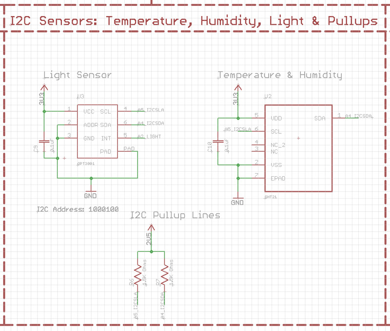
As you have experience in using the I2C components i'm using here, could you have a quick look at the following at just let me know that they are okay and will not be conflicting on the I2C lines. I have looked into the addressing and i hope i have done accordingly.
If the Temp reading is completely off the accuracy due to its location i will just use it to compensate for the temp on the Carbon Monoxide sensor.
-
Because i'm clueless on the software sides of this, i'd like to ask someone from the @Code-Contributor group to give me their opinion on whether or not i would need some external memory on this module. The code will be including:
- Carbon Monoxide Sensor
- Smoke Sensor
- Optical Sensor
- Ambient light
- Temperature and humidity
- Radio
- PIR Motion Sensor
- ATSHA security IC.
-
for example, I would use an eeprom for:
- dualoptiboot ota option
- events or datalogging option
- etc
but I'm not sure if you really need it for datalogging here..
-
for example, I would use an eeprom for:
- dualoptiboot ota option
- events or datalogging option
- etc
but I'm not sure if you really need it for datalogging here..
@scalz, I was just worried about the size of the software to be honest. I initially wanted this to have 'modes', a day and a night mode. But this is only really for the use of the PIR Motion detector. So, I'm now thinking of having a option/switch inside of OpenHAB where i can manually toggle it or have the clock toggle this switch which would then turn the motion sensor on (the mosfet that is acting as a switch).
So after considering my alterations, i think for now as i'm opting for the manual switch option, i won't need any extra EEPROM as the on-board amount of the Atmega328p should be more than enough for my needs. In terms of the bootloader, i'm thinking of going for a branch of Optiboot normal. Then if i do switch my controller to MYScontroller i will switch the bootloader over to that of MYSbootloader to allow for OTA software updates.
I'm still toying with the option of adding a USB/FTDI IC on-board to be done with the FTDI header for the 'new guys' to be able to just plug straight into a usb port as i plan on making these if anyone wants them and then therefor i will be bootloading and fuse setting myself, then they wouldn't need to have access to the ISP port that way either... So a nice handy little USB port on the side of the module casing would be all they need access too, and the AC input terminals obviously.
Did you get a chance to have a look at my I2C components above?
-
@Samuel235
I have looked a bit.For your i2c sensors, if you want you can add a 10k pullup on light int pin. That's all, but not really mandatory, internal pullups works ..nothing fancy. that should work ;)
Your opamp circuit, seems ok, but I can't tell more as these things need testing, simulation. as you noticed analog is not as easy as it appears lol :) btw simulation circuit tools are nice for checking and understanding concept or circuit (like spice, isis etc..). careful with copy of block sch, it's better to understand, for debug then ;)
Last notes, I would add some debug points for analog parts so you can measure voltage easily during debug phase. because it's possible that things change a bit, breadboard vs pcb, as your sensor is in mV range.
Keep up the good work, can't wait to see your device :)
@scalz, 10k Pullup has been implimented. I did have it in and for some reason I now remember deleting it, not too sure why i did such a thing. I will get some pads added on the analog lines like you advise to enable easy testing, do you advise to just add some pads on the lines that i would like to test?
-
The last sensor to be configured and to actually even get working now is the optical smoke sensor. I'm currently having some issues and troubles with even getting the concept of the reflective IR optical sensor to work. Been attempting for days now, hopefully will get this issue sorted ASAP as this is the really holding the module still now. Once this is done, i have a little work on the external powering to do but that shouldn't be too trivial and we can get the board sent off to the board house for manufacturing then.
-
Optical Sensors
While we're on the topic of optical sensors, all the market research that i am doing currently regarding these types of sensors just shows how many products are using optical sensors in the reflective setup, where the smoke causes the IR light to be reflected from the LED into a phototransistor and then therefor change the analog reading of the transistor. They seem to be choosing this over the 'Interrupt' method of having a IR LED shining into a Phototransistor and then smoke interrupting the light rays and therefor changing the properties of the transistor.
Can anyone see an advantage from this other than i would personally feel it is less likely to produce false triggers?
If this is the only reason it would be more beneficial to use the reflective method, i'm thinking about attempting to overcome the false triggers as the 'interrupt' setup method uses a much lower area on the board. If we could work around these false triggers i feel that it would benefit this setup much more.
I'm pretty sure that the power usage is the same because the LED would be permanently on at the same level for both methods.
-
I have just purchased some photo diodes rather than photo transistors to attempt to get this working. From what i have been reading, the photo transistors are around 100 times more sensitive than photo diodes and therefor i'm thinking that it could be this that is causing me an issue with trying to record the reflecting IR Light off of the smoke.
-
To keep you guys updated regarding the progress of this module;
I've been having some issues with creating a chamber that is capable of holding the diodes, transistors and the smoke without letting ambient light in (Due to materials and method, not due to design ability). So I decided to purchase a cheap (£10) Optical Smoke Detector from my local merchants, turns out to be a pretty nice device for the price. I have opened up the unit to find the smoke chamber and various other electronics inside, looks pretty nicely made. After a few google searches i have discovered what appears to be a full blown MCU inside of there, i will do some more investigation and post some part numbers up here soon for you guys to have a look around for interest sake. But normally i see smoke application specific IC's inside of these, so i was shocked at the MCU that is in there with no mention to smoke on the datasheet from what i could see. I'm now wondering if there would be some what to interface with this MCU to my ATMEGA. We will see with some further investigations.
My initial plans for this now were to rip out the chamber and the detection hardware inside of this chamber, and allocate a space on my module to receive this hardware rather than making my own, saving time and hassle as this is already a proved to work method.
P.S - I'm working on a double relay board that uses its own AC INPUT line to feed the live power to the relays and therefor not needing multiple AC supply to power something. This module is allowed to power two devices at a maximum of 2A on each relay, protected through 2 2A SMD fuses. I will release details very soon ;)
-
I'm currently spending today reverse engineering a optical smoke alarm to see how its chamber is connected to its op amp. It is taking an awfully long time due to the black silkscreen. Very hard to trace the routes from components.
-
UPDATE:
We now have the optical smoke sensor working, sort of. The only issue we have now is that the output on the OP AMP for the smoke sensor is oscillating, soon as i can rectify this to a DC voltage, we should be good to go with this module. Looking forward to layout this board!
-
UPDATE:
We now have a working optical smoke sensor!
Just to recap on the sensors on board:
- Optical Smoke Sensor
- Electrochemical Carbon Monoxide Sensor
- Motion Sensor
- Temperature Sensor
- Humidity Sensor
- Light Sensor
I'm just wondering if there will be enough on-board memory for the software and libraries for these sensors. I suppose the sensible thing to do here would be to get the software to a somewhat working state and then we could see how much memory we really need....
Software Gurus, please come forward and make yourself known please!
I do plan on having multiple states/profiles allowed on this module, something like Day state, Night state and an away state maybe. Not sure how much extra software that would take, not much i should imagine as it would only be to change a few states of the sensors.
But seriously, anyone involved with software that seems interested in being involved with this, please make yourself known here or message me and we can progress from here.
Thanks,
Sam. -
hi.
cool :) perhaps you should try to draft a sketch and see what you get for memory usage. always good to check this before ;)
i am actually busy doing sw for my different modules so i won't have too much time on my side :confused: and there are so much things i would like to do! But if you need some help, you still can ask, we will try to help :smile: -
hi.
cool :) perhaps you should try to draft a sketch and see what you get for memory usage. always good to check this before ;)
i am actually busy doing sw for my different modules so i won't have too much time on my side :confused: and there are so much things i would like to do! But if you need some help, you still can ask, we will try to help :smile:@scalz, thank you. I'm sure I will need help from someone at some point, however i will keep this thread updated with my position on the software for this module. I know this is taking me a long time but this is a very complex module for me, hardware and software, the most complex i have ever done with electronics up to this point, but i'm loving every single instance of problem solving i'm going through!
A quick sketchup will be done ASAP hopefully to see the memory usage, i'm just wondering if there is any point in putting external memory on-board just for the sake of it, not much added to the cost and will allow for future capabilities.
MySensors 2.1.1
Controller - OpenHAB (Virtual Machine)
Gateway - Arduino Mega MQTT Gateway W5100
Hello! It looks like you're interested in this conversation, but you don't have an account yet.
Getting fed up of having to scroll through the same posts each visit? When you register for an account, you'll always come back to exactly where you were before, and choose to be notified of new replies (either via email, or push notification). You'll also be able to save bookmarks and upvote posts to show your appreciation to other community members.
With your input, this post could be even better 💗
Register Login