Serial gateway with several sensors connected to it
-
@TimO
So I have made a sketch of my setup: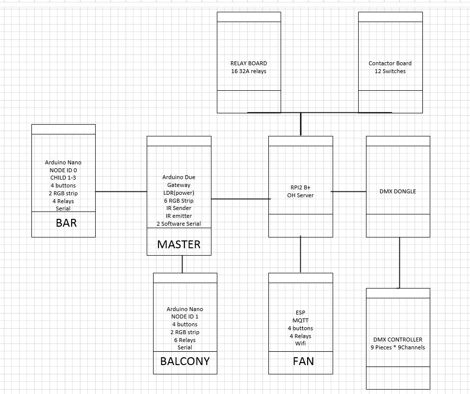
I also started to modify the bar.ino code with the input from you:
// Enable debug prints
//#define MY_DEBUG


#include <MySensor.h>


#define CHILD_ID_SPRIT 0
#define CHILD_ID_WINE 1
#SLEEP_TIME 0


//unsigned long SLEEP_TIME = 30000; // Sleep time between reads (in milliseconds)
// constants won't change. They're used here to
// set pin numbers:
const int buttonPinSpritOpp = 9;     // the number of the pushbutton pin
const int buttonPinSpritNed = 12;     // the number of the pushbutton pin
const int buttonPinVinOpp = 10;     // the number of the pushbutton pin
const int buttonPinVinNed = 11;     // the number of the pushbutton pin

const int ledPinSpritOpp = 4;     // the number of the pushbutton pin
const int ledPinSpritNed = 8;     // the number of the pushbutton pin
const int ledPinVinOpp = 7;     // the number of the pushbutton pin
const int ledPinVinNed = 3;     // the number of the pushbutton pin

const int motorPinVin =  A3;      // the number of the motor pin
const int motorPinOnVin =A1;
const int motorPinOnSprit = A2;//
const int motorPinSprit =  A0;      // the number of the motor pin

int intCode =-1;

MyMessage msgHum(CHILD_ID_SPRIT, V_STATUS);
MyMessage msgTemp(CHILD_ID_WINE, V_STATUS);

void setup()
{
  // initialize the motor pin as an output:
  pinMode(motorPinSprit, OUTPUT);
  pinMode(motorPinVin, OUTPUT);
  pinMode(motorPinOnSprit, OUTPUT);
  pinMode(motorPinOnVin, OUTPUT);

  // initialize the pushbutton pin as an input:
  pinMode(buttonPinSpritOpp, INPUT_PULLUP);
  pinMode(buttonPinSpritNed, INPUT_PULLUP);
  pinMode(buttonPinVinOpp, INPUT_PULLUP);
  pinMode(buttonPinVinNed, INPUT_PULLUP);


   // Default values
  digitalWrite(motorPinSprit,HIGH);
  digitalWrite(motorPinVin,HIGH);
  digitalWrite(motorPinOnSprit, HIGH);
  digitalWrite(motorPinOnVin, HIGH);
}

void presentation()
{
  // Send the Sketch Version Information to the Gateway
  sendSketchInfo("BAR", "1.0");

  // Register all sensors to gw (they will be created as child devices)
  present(CHILD_ID_SPRIT, S_BINARY);
  present(CHILD_ID_WINE, S_BINARY);
}

void loop()
{

   if ((digitalRead(buttonPinSpritOpp) == HIGH && digitalRead(buttonPinSpritNed) == LOW) || intCode==1) {
    digitalWrite(motorPinSprit,LOW);
    digitalWrite(motorPinOnSprit,LOW);
    digitalWrite(ledPinSpritOpp,HIGH);
    digitalWrite(ledPinSpritNed,LOW);

    send(msg.set(0));

    #ifdef MY_DEBUG
    Serial.println("Sprit opp");
    #endif
  }


  else if ((digitalRead(buttonPinSpritOpp) == LOW && digitalRead(buttonPinSpritNed) == HIGH)|| intCode==2) {
    digitalWrite(motorPinSprit,HIGH);
    digitalWrite(motorPinOnSprit,LOW);
    digitalWrite(ledPinSpritNed,HIGH);
    digitalWrite(ledPinSpritOpp,LOW);

    send(msg.set(1));
    #ifdef MY_DEBUG
    Serial.println("Sprit ned");
    #endif
  }

  else{
    digitalWrite(motorPinSprit,HIGH);
    digitalWrite(motorPinOnSprit,HIGH);
    digitalWrite(ledPinSpritOpp,LOW);
    digitalWrite(ledPinSpritNed,LOW);
  }

  if ((digitalRead(buttonPinVinOpp) == HIGH && digitalRead(buttonPinVinNed) == LOW) || intCode==3) {
    digitalWrite(motorPinOnVin,LOW);
    digitalWrite(motorPinVin,LOW);
    digitalWrite(ledPinVinOpp,HIGH);
    digitalWrite(ledPinVinNed,LOW);
    send(msg.set(0));
    #ifdef MY_DEBUG
    Serial.println("Vin opp");
    #endif
  }


  else if ((digitalRead(buttonPinVinOpp) == LOW && digitalRead(buttonPinVinNed) == HIGH)|| intCode==4) {
    digitalWrite(motorPinVin,HIGH);
    digitalWrite(motorPinOnVin,LOW);
    digitalWrite(ledPinVinNed,HIGH);
    digitalWrite(ledPinVinOpp,LOW);

    send(msg.set(1));
    #ifdef MY_DEBUG
    Serial.println("Vin ned");
    #endif
  }

  else {
    digitalWrite(motorPinVin,HIGH);
    digitalWrite(motorPinOnVin,HIGH);
    digitalWrite(ledPinVinOpp,LOW);
    digitalWrite(ledPinVinNed,LOW);
  }

  if (intCode==0){
    digitalWrite(motorPinOnVin,HIGH);
    digitalWrite(motorPinOnSprit,HIGH);
    digitalWrite(ledPinSpritOpp,LOW);
    digitalWrite(ledPinSpritNed,LOW);
    digitalWrite(ledPinVinOpp,LOW);
    digitalWrite(ledPinVinNed,LOW);

    #ifdef MY_DEBUG
    Serial.println("Shutting off");
    #endif
  }

  }


  sleep(SLEEP_TIME); //sleep a bit
}

void receive(const MyMessage &message) {
  // We only expect one type of message from controller. But we better check anyway.
  if (message.type==V_STATUS) {
     // Change relay state
     if message.sensor == CHILD_ID_SPRIT){
         if message.getBool(){
           intCode = 1;
         else{
           intCode = 2;
         }
     }
     if message.sensor == CHILD_ID_WINE){
         if message.getBool(){
           intCode = 3;
         else{
           intCode = 4;
         }
     }
     // Store state in eeprom
     //saveState(message.sensor, message.getBool());
     // Write some debug info
     Serial.print("Incoming change for sensor:");
     Serial.print(message.sensor);
     Serial.print(", New status: ");
     Serial.println(message.getBool());
   }
There are a few things unclear to me: How do I define the baudrate of the serial?
Then its the actual sending to the gateway:send(msg.set(0));so how does this msg object work? I need two of these objects one for child node 1 and for child node 2 right?
Then lets move to the RPI, This will then send out 1;2;3;0;2;1/n which then should send it to the gateway arduino which then parses this and send it out with baudrate 9600 on software serial on pin 11, which then will be received by the code above and the wine comes down.
So how should my serial gateway sketch look like? And how do I get feedback from my node (rx pin 10 on due) back to RPI?
Thanks for the tips so far:)
@skatun I don't now if I understand your question... but will give it a try. Basic setup
- The MySensors gateway should talk to your controller (OpenHab) making use of the Serial protocol. You can use an Rpi to host your controller.
- any sensors you want to connect the the MySensors network should talk via this gateway to you controller.
- The MySensors network was/is designed to communicate via Radio (nRF24L01 and others) between the nodes and gateway. Recently it has been made possible to use wired communication (RS485).
- Sensors will be connected to the nodes and communicate with the gateway. In the development edition of MySensors you can also connect the sensors directy to the gateway.
So from there on...
- The baud rate of the (HW) serial is defined in the MySensors library (default 115200).
- You use the send message like "send(messageHum.set(humvalue))" to send values from the sensor to the gateway (which sends it to the controller)
-
@TimO
So I have made a sketch of my setup:I also started to modify the bar.ino code with the input from you:
// Enable debug prints
//#define MY_DEBUG


#include <MySensor.h>


#define CHILD_ID_SPRIT 0
#define CHILD_ID_WINE 1
#SLEEP_TIME 0


//unsigned long SLEEP_TIME = 30000; // Sleep time between reads (in milliseconds)
// constants won't change. They're used here to
// set pin numbers:
const int buttonPinSpritOpp = 9;     // the number of the pushbutton pin
const int buttonPinSpritNed = 12;     // the number of the pushbutton pin
const int buttonPinVinOpp = 10;     // the number of the pushbutton pin
const int buttonPinVinNed = 11;     // the number of the pushbutton pin

const int ledPinSpritOpp = 4;     // the number of the pushbutton pin
const int ledPinSpritNed = 8;     // the number of the pushbutton pin
const int ledPinVinOpp = 7;     // the number of the pushbutton pin
const int ledPinVinNed = 3;     // the number of the pushbutton pin

const int motorPinVin =  A3;      // the number of the motor pin
const int motorPinOnVin =A1;
const int motorPinOnSprit = A2;//
const int motorPinSprit =  A0;      // the number of the motor pin

int intCode =-1;

MyMessage msgHum(CHILD_ID_SPRIT, V_STATUS);
MyMessage msgTemp(CHILD_ID_WINE, V_STATUS);

void setup()
{
  // initialize the motor pin as an output:
  pinMode(motorPinSprit, OUTPUT);
  pinMode(motorPinVin, OUTPUT);
  pinMode(motorPinOnSprit, OUTPUT);
  pinMode(motorPinOnVin, OUTPUT);

  // initialize the pushbutton pin as an input:
  pinMode(buttonPinSpritOpp, INPUT_PULLUP);
  pinMode(buttonPinSpritNed, INPUT_PULLUP);
  pinMode(buttonPinVinOpp, INPUT_PULLUP);
  pinMode(buttonPinVinNed, INPUT_PULLUP);


   // Default values
  digitalWrite(motorPinSprit,HIGH);
  digitalWrite(motorPinVin,HIGH);
  digitalWrite(motorPinOnSprit, HIGH);
  digitalWrite(motorPinOnVin, HIGH);
}

void presentation()
{
  // Send the Sketch Version Information to the Gateway
  sendSketchInfo("BAR", "1.0");

  // Register all sensors to gw (they will be created as child devices)
  present(CHILD_ID_SPRIT, S_BINARY);
  present(CHILD_ID_WINE, S_BINARY);
}

void loop()
{

   if ((digitalRead(buttonPinSpritOpp) == HIGH && digitalRead(buttonPinSpritNed) == LOW) || intCode==1) {
    digitalWrite(motorPinSprit,LOW);
    digitalWrite(motorPinOnSprit,LOW);
    digitalWrite(ledPinSpritOpp,HIGH);
    digitalWrite(ledPinSpritNed,LOW);

    send(msg.set(0));

    #ifdef MY_DEBUG
    Serial.println("Sprit opp");
    #endif
  }


  else if ((digitalRead(buttonPinSpritOpp) == LOW && digitalRead(buttonPinSpritNed) == HIGH)|| intCode==2) {
    digitalWrite(motorPinSprit,HIGH);
    digitalWrite(motorPinOnSprit,LOW);
    digitalWrite(ledPinSpritNed,HIGH);
    digitalWrite(ledPinSpritOpp,LOW);

    send(msg.set(1));
    #ifdef MY_DEBUG
    Serial.println("Sprit ned");
    #endif
  }

  else{
    digitalWrite(motorPinSprit,HIGH);
    digitalWrite(motorPinOnSprit,HIGH);
    digitalWrite(ledPinSpritOpp,LOW);
    digitalWrite(ledPinSpritNed,LOW);
  }

  if ((digitalRead(buttonPinVinOpp) == HIGH && digitalRead(buttonPinVinNed) == LOW) || intCode==3) {
    digitalWrite(motorPinOnVin,LOW);
    digitalWrite(motorPinVin,LOW);
    digitalWrite(ledPinVinOpp,HIGH);
    digitalWrite(ledPinVinNed,LOW);
    send(msg.set(0));
    #ifdef MY_DEBUG
    Serial.println("Vin opp");
    #endif
  }


  else if ((digitalRead(buttonPinVinOpp) == LOW && digitalRead(buttonPinVinNed) == HIGH)|| intCode==4) {
    digitalWrite(motorPinVin,HIGH);
    digitalWrite(motorPinOnVin,LOW);
    digitalWrite(ledPinVinNed,HIGH);
    digitalWrite(ledPinVinOpp,LOW);

    send(msg.set(1));
    #ifdef MY_DEBUG
    Serial.println("Vin ned");
    #endif
  }

  else {
    digitalWrite(motorPinVin,HIGH);
    digitalWrite(motorPinOnVin,HIGH);
    digitalWrite(ledPinVinOpp,LOW);
    digitalWrite(ledPinVinNed,LOW);
  }

  if (intCode==0){
    digitalWrite(motorPinOnVin,HIGH);
    digitalWrite(motorPinOnSprit,HIGH);
    digitalWrite(ledPinSpritOpp,LOW);
    digitalWrite(ledPinSpritNed,LOW);
    digitalWrite(ledPinVinOpp,LOW);
    digitalWrite(ledPinVinNed,LOW);

    #ifdef MY_DEBUG
    Serial.println("Shutting off");
    #endif
  }

  }


  sleep(SLEEP_TIME); //sleep a bit
}

void receive(const MyMessage &message) {
  // We only expect one type of message from controller. But we better check anyway.
  if (message.type==V_STATUS) {
     // Change relay state
     if message.sensor == CHILD_ID_SPRIT){
         if message.getBool(){
           intCode = 1;
         else{
           intCode = 2;
         }
     }
     if message.sensor == CHILD_ID_WINE){
         if message.getBool(){
           intCode = 3;
         else{
           intCode = 4;
         }
     }
     // Store state in eeprom
     //saveState(message.sensor, message.getBool());
     // Write some debug info
     Serial.print("Incoming change for sensor:");
     Serial.print(message.sensor);
     Serial.print(", New status: ");
     Serial.println(message.getBool());
   }
There are a few things unclear to me: How do I define the baudrate of the serial?
Then its the actual sending to the gateway:send(msg.set(0));so how does this msg object work? I need two of these objects one for child node 1 and for child node 2 right?
Then lets move to the RPI, This will then send out 1;2;3;0;2;1/n which then should send it to the gateway arduino which then parses this and send it out with baudrate 9600 on software serial on pin 11, which then will be received by the code above and the wine comes down.
So how should my serial gateway sketch look like? And how do I get feedback from my node (rx pin 10 on due) back to RPI?
Thanks for the tips so far:)
@skatun said:
There are a few things unclear to me: How do I define the baudrate of the serial?
Its defined in MyConfig.h and is normal set to 115200.
Then its the actual sending to the gateway:
send(msg.set(0));so how does this msg object work? I need two of these objects one for child node 1 and for child node 2 right?
You can read some more here: http://www.mysensors.org/download/sensor_api_15#the-full-api
Also check out the examples to figure out how it works.
Two childs can be coded like this for example:#define BARO_CHILD 0
#define TEMP_CHILD 1MyMessage tempMsg(TEMP_CHILD, V_TEMP);
MyMessage pressureMsg(BARO_CHILD, V_PRESSURE);
MyMessage forecastMsg(BARO_CHILD, V_FORECAST);gw.present(BARO_CHILD, S_BARO);
gw.present(TEMP_CHILD, S_TEMP);gw.send(pressureMsg.set(pressure, 0));
Edit, Sorry @AWI didnt see your post there :)
-
@skatun I don't now if I understand your question... but will give it a try. Basic setup
- The MySensors gateway should talk to your controller (OpenHab) making use of the Serial protocol. You can use an Rpi to host your controller.
- any sensors you want to connect the the MySensors network should talk via this gateway to you controller.
- The MySensors network was/is designed to communicate via Radio (nRF24L01 and others) between the nodes and gateway. Recently it has been made possible to use wired communication (RS485).
- Sensors will be connected to the nodes and communicate with the gateway. In the development edition of MySensors you can also connect the sensors directy to the gateway.
So from there on...
- The baud rate of the (HW) serial is defined in the MySensors library (default 115200).
- You use the send message like "send(messageHum.set(humvalue))" to send values from the sensor to the gateway (which sends it to the controller)
@AWI
1: Yes it is, baudrate 115200
2: OK
3: I am using software serial at 9600(long cables) instead of 485 because then i dont need extra hardware.
4: yes, LDR,6 rgb strip,IR sender,IR emitter are connected directlySo from there on...
1: How to modify the code to use software serial instead of radio/485?
2:
bar.ino should then have:MyMessage msgWine(CHILD_ID_SPRIT, V_STATUS); //and in the loop gw.send(msgWine.set(0)); #ifdef MY_DEBUG Serial.println("Sprit opp"); #endifNow it will send that message out everytime the button is pressed, so I need to modify the code a bit to only send it out if it once every 12s(yes you need to hold the button for 12s to run the motor to the end.) I guess the best would be to rewrite the arduino code so that a single push on the button runs the motor for 12s instead of holding it in for 12s.
Thanks for the help so far...
-
@AWI
1: Yes it is, baudrate 115200
2: OK
3: I am using software serial at 9600(long cables) instead of 485 because then i dont need extra hardware.
4: yes, LDR,6 rgb strip,IR sender,IR emitter are connected directlySo from there on...
1: How to modify the code to use software serial instead of radio/485?
2:
bar.ino should then have:MyMessage msgWine(CHILD_ID_SPRIT, V_STATUS); //and in the loop gw.send(msgWine.set(0)); #ifdef MY_DEBUG Serial.println("Sprit opp"); #endifNow it will send that message out everytime the button is pressed, so I need to modify the code a bit to only send it out if it once every 12s(yes you need to hold the button for 12s to run the motor to the end.) I guess the best would be to rewrite the arduino code so that a single push on the button runs the motor for 12s instead of holding it in for 12s.
Thanks for the help so far...
@skatun I have never used a wired connection between two nodes but reading from the RS485 thread it sounds like this class is using the arduino HW serial implementation.
Guess you will need to take a deep dive in the code to change this... -
@skatun: Have a look at this example: https://github.com/mysensors/Arduino/blob/development/libraries/MySensors/examples/GatewaySerialRS485/GatewaySerialRS485.ino
I don't think you have to change the code, just interconnect both Arduinos and keep in mind that PIN 2 is used by the library for DE-PIN management, which you don't need, but can't use for other things.
-
@skatun: Have a look at this example: https://github.com/mysensors/Arduino/blob/development/libraries/MySensors/examples/GatewaySerialRS485/GatewaySerialRS485.ino
I don't think you have to change the code, just interconnect both Arduinos and keep in mind that PIN 2 is used by the library for DE-PIN management, which you don't need, but can't use for other things.
@TimO
From the link:- Arduino Uno 9 8 10
Can I not use rx/tx on my node arduino? (Pin 0/1)
Same goes for my gateway, currently I am using pin 10/11. If I can fix this in software it would be better, then i dont have to resolder my setup, also what happens when you have two rs232 nodes connected to the gateway?
-
In the example SoftSerial (a library) is used and not hardware serial (Pin 0/1).
The node could use hardware serial, if you disable debug and look into the thread about RS485. If I recall it correctly there is a hardware serial implementation but you have to implement it yourself, this is not covered by the library.The GatewaySerialRS485 uses SoftSerial on the connection to the nodes and HardwareSerial on the connection to the controller.
Node <-- (SoftSerial) --> Gateway <-- (HardSerial) --> Controller
With RS485 you're able interconnect more than two devices and use DE_PIN before transmitting data. With RS232 you're limited to two devices or are in need of additional SoftSerial / HardSerial (and therefore additional PINs) depending on your hardware.
@TimO
I will look into it, however first I need to get the gateway up running.So I am struggling to see how locally attached sensors work. I guess (reading several forum entry) that gw object is not needed. What is this inclusion mode? Is that part of the code needed?
However I can not get my code to compile:
#include <SPI.h> #include <MySensor.h> // Enable debug prints to serial monitor #define MY_DEBUG // Enable serial gateway #define MY_GATEWAY_SERIAL // Flash leds on rx/tx/err #define MY_LEDS_BLINKING_FEATURE // Set blinking period #define MY_DEFAULT_LED_BLINK_PERIOD 300 // Enable inclusion mode #define MY_INCLUSION_MODE_FEATURE // Enable Inclusion mode button on gateway #define MY_INCLUSION_BUTTON_FEATURE // Set inclusion mode duration (in seconds) #define MY_INCLUSION_MODE_DURATION 60 // Digital pin used for inclusion mode button #define MY_INCLUSION_MODE_BUTTON_PIN 3 #define DIGITAL_INPUT_SENSOR 3 // The digital input you attached your light sensor. (Only 2 and 3 generates interrupt!) #define PULSE_FACTOR 1000 // Nummber of blinks per KWH of your meeter #define SLEEP_MODE false // Watt-value can only be reported when sleep mode is false. #define MAX_WATT 10000 // Max watt value to report. This filetrs outliers. #define INTERRUPT DIGITAL_INPUT_SENSOR-2 // Usually the interrupt = pin -2 (on uno/nano anyway) #define CHILD_ID 9 // Id of the sensor child unsigned long SEND_FREQUENCY = 20000; // Minimum time between send (in milliseconds). We don't wnat to spam the gateway. MySensor gw; double ppwh = ((double)PULSE_FACTOR)/1000; // Pulses per watt hour boolean pcReceived = false; volatile unsigned long pulseCount = 0; volatile unsigned long lastBlink = 0; volatile unsigned long watt = 0; unsigned long oldPulseCount = 0; unsigned long oldWatt = 0; double oldKwh; unsigned long lastSend; MyMessage wattMsg(CHILD_ID,V_WATT); MyMessage kwhMsg(CHILD_ID,V_KWH); MyMessage pcMsg(CHILD_ID,V_VAR1); void setup() { attachInterrupt(INTERRUPT, onPulse, RISING); lastSend=millis(); } void presentation() { // Present locally attached sensors here // Register this device as power sensor gw.present(CHILD_ID, S_POWER,"Energy Meter"); } void loop() { gw.process(); unsigned long now = millis(); // Only send values at a maximum frequency or woken up from sleep bool sendTime = now - lastSend > SEND_FREQUENCY; if (pcReceived && (SLEEP_MODE || sendTime)) { // New watt value has been calculated if (!SLEEP_MODE && watt != oldWatt) { // Check that we dont get unresonable large watt value. // could hapen when long wraps or false interrupt triggered if (watt<((unsigned long)MAX_WATT)) { gw.send(wattMsg.set(watt)); // Send watt value to gw } //Serial.print("Watt:"); //Serial.println(watt); oldWatt = watt; } // Pulse cout has changed if (pulseCount != oldPulseCount) { //gw.send(pcMsg.set(pulseCount)); // Send pulse count value to gw double kwh = ((double)pulseCount/((double)PULSE_FACTOR)); oldPulseCount = pulseCount; if (kwh != oldKwh) { gw.send(kwhMsg.set(kwh, 4)); // Send kwh value to gw oldKwh = kwh; } } lastSend = now; } else if (sendTime && !pcReceived) { // No count received. Try requesting it again request(CHILD_ID, V_VAR1); lastSend=now; } if (SLEEP_MODE) { sleep(SEND_FREQUENCY); } } void incomingMessage(const MyMessage &message) { if (message.type==V_VAR1) { pulseCount = oldPulseCount = message.getLong(); //Serial.print("Received last pulse count from gw:"); //Serial.println(pulseCount); pcReceived = true; } } void onPulse() { if (!SLEEP_MODE) { unsigned long newBlink = micros(); unsigned long interval = newBlink-lastBlink; if (interval<10000L) { // Sometimes we get interrupt on RISING return; } watt = (3600000000.0 /interval) / ppwh; lastBlink = newBlink; } pulseCount++; } -
@TimO
I will look into it, however first I need to get the gateway up running.So I am struggling to see how locally attached sensors work. I guess (reading several forum entry) that gw object is not needed. What is this inclusion mode? Is that part of the code needed?
However I can not get my code to compile:
#include <SPI.h> #include <MySensor.h> // Enable debug prints to serial monitor #define MY_DEBUG // Enable serial gateway #define MY_GATEWAY_SERIAL // Flash leds on rx/tx/err #define MY_LEDS_BLINKING_FEATURE // Set blinking period #define MY_DEFAULT_LED_BLINK_PERIOD 300 // Enable inclusion mode #define MY_INCLUSION_MODE_FEATURE // Enable Inclusion mode button on gateway #define MY_INCLUSION_BUTTON_FEATURE // Set inclusion mode duration (in seconds) #define MY_INCLUSION_MODE_DURATION 60 // Digital pin used for inclusion mode button #define MY_INCLUSION_MODE_BUTTON_PIN 3 #define DIGITAL_INPUT_SENSOR 3 // The digital input you attached your light sensor. (Only 2 and 3 generates interrupt!) #define PULSE_FACTOR 1000 // Nummber of blinks per KWH of your meeter #define SLEEP_MODE false // Watt-value can only be reported when sleep mode is false. #define MAX_WATT 10000 // Max watt value to report. This filetrs outliers. #define INTERRUPT DIGITAL_INPUT_SENSOR-2 // Usually the interrupt = pin -2 (on uno/nano anyway) #define CHILD_ID 9 // Id of the sensor child unsigned long SEND_FREQUENCY = 20000; // Minimum time between send (in milliseconds). We don't wnat to spam the gateway. MySensor gw; double ppwh = ((double)PULSE_FACTOR)/1000; // Pulses per watt hour boolean pcReceived = false; volatile unsigned long pulseCount = 0; volatile unsigned long lastBlink = 0; volatile unsigned long watt = 0; unsigned long oldPulseCount = 0; unsigned long oldWatt = 0; double oldKwh; unsigned long lastSend; MyMessage wattMsg(CHILD_ID,V_WATT); MyMessage kwhMsg(CHILD_ID,V_KWH); MyMessage pcMsg(CHILD_ID,V_VAR1); void setup() { attachInterrupt(INTERRUPT, onPulse, RISING); lastSend=millis(); } void presentation() { // Present locally attached sensors here // Register this device as power sensor gw.present(CHILD_ID, S_POWER,"Energy Meter"); } void loop() { gw.process(); unsigned long now = millis(); // Only send values at a maximum frequency or woken up from sleep bool sendTime = now - lastSend > SEND_FREQUENCY; if (pcReceived && (SLEEP_MODE || sendTime)) { // New watt value has been calculated if (!SLEEP_MODE && watt != oldWatt) { // Check that we dont get unresonable large watt value. // could hapen when long wraps or false interrupt triggered if (watt<((unsigned long)MAX_WATT)) { gw.send(wattMsg.set(watt)); // Send watt value to gw } //Serial.print("Watt:"); //Serial.println(watt); oldWatt = watt; } // Pulse cout has changed if (pulseCount != oldPulseCount) { //gw.send(pcMsg.set(pulseCount)); // Send pulse count value to gw double kwh = ((double)pulseCount/((double)PULSE_FACTOR)); oldPulseCount = pulseCount; if (kwh != oldKwh) { gw.send(kwhMsg.set(kwh, 4)); // Send kwh value to gw oldKwh = kwh; } } lastSend = now; } else if (sendTime && !pcReceived) { // No count received. Try requesting it again request(CHILD_ID, V_VAR1); lastSend=now; } if (SLEEP_MODE) { sleep(SEND_FREQUENCY); } } void incomingMessage(const MyMessage &message) { if (message.type==V_VAR1) { pulseCount = oldPulseCount = message.getLong(); //Serial.print("Received last pulse count from gw:"); //Serial.println(pulseCount); pcReceived = true; } } void onPulse() { if (!SLEEP_MODE) { unsigned long newBlink = micros(); unsigned long interval = newBlink-lastBlink; if (interval<10000L) { // Sometimes we get interrupt on RISING return; } watt = (3600000000.0 /interval) / ppwh; lastBlink = newBlink; } pulseCount++; }@skatun it looks like you are mixing the development version 2.0 and master branch 1.5 syntax. In development the "class" setup is removed and therefore for "gw." is not used anymore.
Most of the examples use the gw. Structure though. Look at the samples in the development branch as you will probably want/need the new functionality
-
@skatun it looks like you are mixing the development version 2.0 and master branch 1.5 syntax. In development the "class" setup is removed and therefore for "gw." is not used anymore.
Most of the examples use the gw. Structure though. Look at the samples in the development branch as you will probably want/need the new functionality
@AWI
So I copied ower evrything in the library folder of the development branch. When i then try to compile the serial gateway i get this error:Arduino: 1.6.7 (Windows 7), Board: "NodeMCU 1.0 (ESP-12E Module), 80 MHz, Serial, 115200, 4M (3M SPIFFS)" In file included from C:\Program Files (x86)\Arduino\libraries\MySensors\examples\SerialGateway\SerialGateway.ino:50:0: C:\Program Files (x86)\Arduino\libraries\MySensors/MySensor.h:285:4: error: #error No forward link or gateway feature activated. This means nowhere to send messages! Pretty pointless. #error No forward link or gateway feature activated. This means nowhere to send messages! Pretty pointless. ^ In file included from C:\Program Files (x86)\Arduino\libraries\MySensors\examples\SerialGateway\SerialGateway.ino:52:0: C:\Program Files (x86)\Arduino\libraries\PinChangeInt/PinChangeInt.h:103:19: fatal error: new.h: No such file or directory #include <new.h> ^ compilation terminated. exit status 1 Error compiling. This report would have more information with "Show verbose output during compilation" enabled in File > Preferences. -
@skatun It's hard to tell (for me ;-)) from the messages what is going wrong. Which Arduino are you programming for? Are you using the "GatewaySerial.ino" sketch from the development branch examples?
-
@AWI
I just copied all the files in libraries and hardware in the development zip into c:\program files\Arduino\I am trying to get it to run on arduino due and yes I was trying the run the Serial gateway in Library\My Sensor\SerialGateway
-
Hi @skatun did you check this http://www.mysensors.org/about/arduino#installing-the-sensor-libraries ? You install it the same way but download it from https://github.com/mysensors/Arduino (press Download ZIP) and make sure its Branch: Development.
Controller: Proxmox VM - Home Assistant
MySensors GW: Arduino Uno - W5100 Ethernet, Gw Shield Nrf24l01+ 2,4Ghz
MySensors GW: Arduino Uno - Gw Shield RFM69, 433mhz
RFLink GW - Arduino Mega + RFLink Shield, 433mhz -
Hi @skatun did you check this http://www.mysensors.org/about/arduino#installing-the-sensor-libraries ? You install it the same way but download it from https://github.com/mysensors/Arduino (press Download ZIP) and make sure its Branch: Development.
Well I tried to save it both here:
C:\Program Files (x86)\Arduino\libraries\Mysensor
C:\Program Files (x86)\Arduino\hardware\MySensorsAs well as here as described in your link:
C:\Users\kim\Documents\ArduinoBut I get compile errors no matter where I try to compile serialgateway on due which I found in the C:\Program Files (x86)\Arduino\libraries\MySensors\examples\SerialGateway
Cheers
-
@skatun having the files in multiple folders isnt a good idea.
Maybe you should remove the IDE and all folders and start over?Controller: Proxmox VM - Home Assistant
MySensors GW: Arduino Uno - W5100 Ethernet, Gw Shield Nrf24l01+ 2,4Ghz
MySensors GW: Arduino Uno - Gw Shield RFM69, 433mhz
RFLink GW - Arduino Mega + RFLink Shield, 433mhz -
@skatun having the files in multiple folders isnt a good idea.
Maybe you should remove the IDE and all folders and start over?@sundberg84
So the IDE by default get installed C:\Program Files (x86)\Arduino but the files folder get default set to this:C:\Users\kim\Documents\Arduino
I guess arduino made it that way so that you can load examples from C:\Program Files (x86)\Arduino then mess around with them and save them here C:\Users\kim\Documents\Arduino
So I never had duplicate files, i tried both locations without sucsess. So which version of the IDE should I use? 1.6.7 is what I have now.
-
@skatun Dont know if there are any version conflicts at the moment.
I dont have the latest version.Controller: Proxmox VM - Home Assistant
MySensors GW: Arduino Uno - W5100 Ethernet, Gw Shield Nrf24l01+ 2,4Ghz
MySensors GW: Arduino Uno - Gw Shield RFM69, 433mhz
RFLink GW - Arduino Mega + RFLink Shield, 433mhz -
@skatun Dont know if there are any version conflicts at the moment.
I dont have the latest version.@sundberg84
So which directory should i put the files in? BOth hardware and library? -
I install the ide. download and extract mys to same path as ide. That's it.
Controller: Proxmox VM - Home Assistant
MySensors GW: Arduino Uno - W5100 Ethernet, Gw Shield Nrf24l01+ 2,4Ghz
MySensors GW: Arduino Uno - Gw Shield RFM69, 433mhz
RFLink GW - Arduino Mega + RFLink Shield, 433mhz