Skip to content
  • MySensors
  • OpenHardware.io
  • Categories
  • Recent
  • Tags
  • Popular
Skins
  • Light
  • Brite
  • Cerulean
  • Cosmo
  • Flatly
  • Journal
  • Litera
  • Lumen
  • Lux
  • Materia
  • Minty
  • Morph
  • Pulse
  • Sandstone
  • Simplex
  • Sketchy
  • Spacelab
  • United
  • Yeti
  • Zephyr
  • Dark
  • Cyborg
  • Darkly
  • Quartz
  • Slate
  • Solar
  • Superhero
  • Vapor

  • Default (No Skin)
  • No Skin
Collapse
Brand Logo
  1. Home
  2. OpenHardware.io
  3. 💬 AC-DC double solid state relay module

💬 AC-DC double solid state relay module

Scheduled Pinned Locked Moved OpenHardware.io
hlk-pm01solid state relaylight switchlightacdc
226 Posts 67 Posters 103.6k Views 65 Watching
  • Oldest to Newest
  • Newest to Oldest
  • Most Votes
Reply
  • Reply as topic
Log in to reply
This topic has been deleted. Only users with topic management privileges can see it.
  • joaoabsJ joaoabs

    Hi,
    Any particular reason for the values of the thermal cut-offs? (73ºC, 10A)?
    This temperature (73ºC) makes it difficult to solder, I've burned a couple when trying to solder it... And why 10A? Shouldn't we get a lower current? I know the other fuse is limiting the current to 0.2A, but if we have a lower current on this one we may get cheaper components... Wouldn't this one, for instance, do the same function? https://www.ebay.com/itm/10-Pcs-Fuji-Microtemp-Thermal-Fuse-115-TF-Cutoff-1A-250V-New/322657006381

    If the PCB is inside a box, without any lossen wires, couldn't we limit the temperature to a sliglhly higher value (115ºC)?

    Thanks

    Nca78N Offline
    Nca78N Offline
    Nca78
    Hardware Contributor
    wrote on last edited by
    #215

    Hello @joaoabs,

    I think it is based on measurements here :
    https://lygte-info.dk/review/Power Mains to 5V 0.6A Hi-Link HLK-PM01 UK.html

    As you can see when he tests at full load (0.6A) for a long time, max temperature is a bit over 60°C. So temperature should not be too much higher than that if you want to detect abnormal overheating. 115° is higher than what is measured at the hottest point on the top of the enclosure after 15mn overloading at twice the maximum load, so I don't think it's safe to use a temp fuse that high.

    For the max current there might be a short inrush current when switching on, so 1A could be a bit low (and that's why the other fuse is a slow blow fuse), but feel free to try and report :)

    1 Reply Last reply
    0
    • T Offline
      T Offline
      TomG
      wrote on last edited by
      #216

      This looks like a great PCB and I'm interested in ordering a few from DirtyPCBs, however OpenHardware.io shows this project as "Work in Progress". Are there any plans to do additional updates to this PCB?

      1 Reply Last reply
      1
      • D Offline
        D Offline
        Damian
        wrote on last edited by Damian
        #217

        Hi,
        did you consider redesigning the PCB using mini nrf24l01+ like this:
        alt text
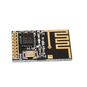
        It could compact the size of the whole device. Moreover it would be great to have GND and Vcc (3.3V or 5V), and 4 GPIO (ie. 2 analog, 2 digital) pins led out on the PCB (there are 6 holes on the edge not used as I understand?). It would be great to have an option to connect some additional sensors (I use 2 dht22 sensors for environment monitoring in some projects).

        1 Reply Last reply
        0
        • Z Offline
          Z Offline
          zombiee77
          wrote on last edited by
          #218

          Unfortunately the Bottom copper layer is corrupted.
          Anybody has a good file for me?

          1 Reply Last reply
          0
          • TmasterT Offline
            TmasterT Offline
            Tmaster
            wrote on last edited by Tmaster
            #219

            how is the board and specially the hlk-pm01 transformer,that is the component that i need more trust ,after 3 years of work?

            i want to make some rolle shutter controllers to replace the expensive and buggy fibaro FGR-223 new modules.

            i'm a arduino fan .Even sometimes don't undestanding how to use it :P

            1 Reply Last reply
            0
            • ilium007I Offline
              ilium007I Offline
              ilium007
              wrote on last edited by
              #220

              What varistor should I use for 240VAC in Australia? The linked AliExpress item is no longer available.

              1 Reply Last reply
              0
              • Q Offline
                Q Offline
                qualle337
                wrote on last edited by
                #221

                Hi all,

                I've got two fully equipped, ready to go soldered v3.3.2 boards, two working USB gateways based on Arduino Nano, as well as 8 unsoldered PCBs (without the parts) to give away. I've used the system in my previous flat and it worked great. However, when I moved I wasn't able to fit them behind my light switches :(((
                I don't have time anymore to solder my own boards and switched to some China Zigbee boards. They use cheap standard relais and do not react as quick as the mysensor module unfortunately. Long story short, they are sitting around in my cupboard and I thought it might help someone to quickly expand their system or to kickstart before investing to much effort.
                I'm based in Germany so I would prefer to ship it to someone in Germany, however if nobody is interested then I would ship it abroad as well. Message me if you're interested :)

                1 Reply Last reply
                0
                • M Offline
                  M Offline
                  mopscrops76
                  Banned
                  wrote on last edited by mfalkvidd
                  #222

                  Unfortunately the Bottom copper layer is corrupted.
                  (Spam links removed by moderator)

                  1 Reply Last reply
                  0
                  • K Offline
                    K Offline
                    kaylestoinis
                    Banned
                    wrote on last edited by
                    #223

                    Does anyone know how to convert diptrace to kicad format? I want to try and edit to make a RFM69 version.

                    A 1 Reply Last reply
                    0
                    • K kaylestoinis

                      Does anyone know how to convert diptrace to kicad format? I want to try and edit to make a RFM69 version.

                      A Offline
                      A Offline
                      Andrea_J
                      wrote on last edited by
                      #224

                      @kaylestoinis In principle, I tried to do it this way and succeeded:

                      • Installed diptrace free
                      • opened the schematic file
                      • exported to eagle
                      • imported eagle file in KiCad
                      • same for the board file
                      1 Reply Last reply
                      0
                      • HonkH Offline
                        HonkH Offline
                        Honk
                        wrote on last edited by
                        #225

                        thanks for the design.
                        I did build a unit in 2018.
                        Today I build one to control the light on my front door. It will be triggered by the IR Motion sensor.
                        The Switch indoors will be just to power the light (and the arduino) off completly.
                        Because of the IR Sensor VCC near the PIN 4 GND GND PIN7 Header.
                        I routed my own with a wire.

                        Never have I soldered a slow blow fuse in one go :)

                        1 Reply Last reply
                        0
                        • OldSurferDudeO Offline
                          OldSurferDudeO Offline
                          OldSurferDude
                          wrote on last edited by
                          #226

                          What I didn't quite figure out was how it operates independently as a regular light switch.

                          What I find most interesting is that this is 8 years old. There have been some incredible advances in the IoT world in that time. I was about to do a similar thing which morphed into an ESP-12F then added a touch screen. I call it the Universal Light Switch

                          Imagine this: All the switches are identical. Any switch can easily be configured to control up to five devices ... and then changed, on-the-fly, to control a different set of devices.

                          My design is part of a system that would require a controller (eg. Home Assistant), an MQTT broker, and receiving modules in the devices being switched. It's WiFI which assumes an access point.

                          The DIY ULS is under $20 and the off-the-shelf receiving modules are under $10. (About the cost of a non-networked dimmer switch) If one doesn't have the controller and MQTT broker, they can run on an old (5 years?) computer (which is cheaper than an old RasberryPi).

                          This project is a good one!

                          OSD

                          1 Reply Last reply
                          0
                          Reply
                          • Reply as topic
                          Log in to reply
                          • Oldest to Newest
                          • Newest to Oldest
                          • Most Votes


                          15

                          Online

                          11.7k

                          Users

                          11.2k

                          Topics

                          113.0k

                          Posts


                          Copyright 2019 TBD   |   Forum Guidelines   |   Privacy Policy   |   Terms of Service
                          • Login

                          • Don't have an account? Register

                          • Login or register to search.
                          • First post
                            Last post
                          0
                          • MySensors
                          • OpenHardware.io
                          • Categories
                          • Recent
                          • Tags
                          • Popular