Smart Light Switch 220v
-
-
Hopping to contribute to the community and your opinions on the board and improvement opportunities!
-
I added a FTDI connector for easy programming of the ATMEGA328
-
Nice project :)
In case..have you checked clearance/creepage? A small article here if you want:
http://blog.optimumdesign.com/clearance-and-creepage-rules-for-pcb-assembly -
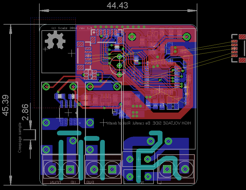
Hi @scalz ! This is my firs project of this magnitude, I'm still learning! My main focus was to make the 220v the safest possible! So I used a calculator to get me the clearance value, and then applied some extra! Another focus was the width of the traces! This is my values:
Clerance / Trace Width (values in mm)
Signal: 0.2 / 0.5
AC Power: 1.2 / 2
AC Power on Relay: 1.2 / 3.5
DC Power: 0.2 / 1What do you guys think? I was looking at the table and it seems good!
My board will be printed at 1,6mm! Do you think that this will be safe to use with the AC current? I have to insure that the traces will handle the max of the relay, this is 2A!
I also raised the width of the pads on the Relays and connections to the relays to grant me a better connections! They are 3mm width!
Best Regards
Soloam -
@soloam : I forgot that it's 2A! I was thinking about more amps and looking to your enlarged pads on bottom. So if you have checked, should be ok, cool.
I'm not a big fan of radio too near of AC lines. seems you have nrf antenna just above Hilink main, hope for not too much EMI and decreased range, but maybe that will work well. I would have placed your fuses near AC connector. And for instance, to have most of AC part on one side, and other DC and radio on opposite side when possible. Easy to say!
See you soon and good luck ;)
-
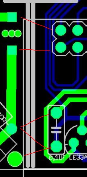
@Soloam - Great project, nice! Im also learning so im no expert but i though about the trace going from "AC 220 In"
It seems really close to the DC/signal traces for Nrf24l01 for examle (red markings):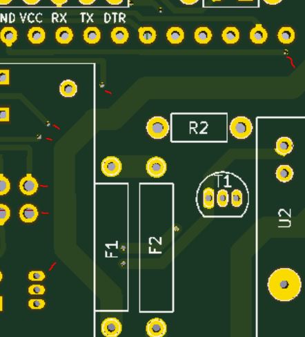 - whats your thoughts?
If you look at for example:
@scalz has seperated the AC (below) and DC side.Also my project i try the same:
-
@Soloam - Great project, nice! Im also learning so im no expert but i though about the trace going from "AC 220 In"
It seems really close to the DC/signal traces for Nrf24l01 for examle (red markings): - whats your thoughts?If you look at for example:
@scalz has seperated the AC (below) and DC side.Also my project i try the same:
I too noticed this but due to me having no clue regarding AC on a PCB still, i chose not to comment. However, i'm about to start my own AC PCB wiring soon so i thought i would now include myself to learn from you guys :)
-
Hello all. I followed your adviesses and moved de NRF24L01 to the top of the board! Now I have all the 220v in the bottom part of the layout! What do you think? (project updated)
I have a question! On the AC 220 Input I have a trace going to the HLK and then to the varistor! I think ther's no problem doing this, but I would like your opinion!
A question, any one knows how to add a Creepage on the KiCad? I looked and can't seem to find it!
Thank you all!
Best Regards -
Hello all. I followed your adviesses and moved de NRF24L01 to the top of the board! Now I have all the 220v in the bottom part of the layout! What do you think? (project updated)
I have a question! On the AC 220 Input I have a trace going to the HLK and then to the varistor! I think ther's no problem doing this, but I would like your opinion!
A question, any one knows how to add a Creepage on the KiCad? I looked and can't seem to find it!
Thank you all!
Best Regards@Soloam said:
I have a question! On the AC 220 Input I have a trace going to the HLK and then to the varistor! I think ther's no problem doing this, but I would like your opinion!
I'm no expert here but I imagine that the layout of your Varistor is perfectly fine. Please don't quote me on this. You can actually have the varistor on the top side of the board and change the position of it to sit where the trace between AC IN and TEMP FUSE and move that trace up slightly without the bend/angles in it so the varistor would now sit before the transformer. However like i said, i don't think it is needed. With this modification you might be able to get a cut into the board to allow for creepage and clearance specs ;)
-
Does anyone have any relevant documents for these relays (G3MB-202P), the only datasheet i can find does not provide the typical current draw to activate them.... I would like to clarify that these are safe to run for the atmega328p pin output current max, allowing for spikes for any reason what so ever.
Having a SMT MCU break is not fun to replace.
-
Here's the data sheet I have for those: G3MB solid state relay.pdf
-
Yes this is the datasheet that I have and used to draw the holes to the relay!
Thank you for the replay @Samuel235 ! Can any one else confirm this to me?
A question! I what to add a ATSHA204A to my board to authentication, but I have a question! Some people use a 0.1uF capacitor and a pull up resistor! Others don't use it! Can any one tell me the reason for that?
@sundberg84 and @scalz what do you think of the layout now, with AC and DC separated?
Thank you all!
When I have all my question answered I can finally order the PCB and test it out! -
Here's the data sheet I have for those: G3MB solid state relay.pdf
-
@Soloam : I have not looked everything but seems better :)
- antenna still above circuit but I guess you want to keep the size. perhaps I would have reduced a little bit trace at AC screwterminals but if you say you have the right creepage, seems ok then.
- For pullup on atsha, maybe not really mandatory, I already tried without one, but it's always better to be sure to have the right voltage level.
- And always better to have it on CS SPI bus pin too. So, if you can add footprint for CS radio pin, it's better too.
- 0.1u capa is for decoupling/filtering/good voltage. Same thing here, it's a better practice to have it for each ic.
- I always try to add a bit more footprints when possible, so I solder what I need. Then if I have trouble I can easily add a component. But it's not always easy as I try to keep things small.
I have not checked everything..but nice rework ;)
-
Hello @scalz ! I'll try the RF in this position! My idea is to put the PCB in wall, and the radio will be facing to the outside, so my hopes are that it will be clear to the signal!
I will try to add the capa and the resistor to the ATSHA204A, but the board is almost full traces!
-
Hello all. I followed your adviesses and moved de NRF24L01 to the top of the board! Now I have all the 220v in the bottom part of the layout! What do you think? (project updated)
I have a question! On the AC 220 Input I have a trace going to the HLK and then to the varistor! I think ther's no problem doing this, but I would like your opinion!
A question, any one knows how to add a Creepage on the KiCad? I looked and can't seem to find it!
Thank you all!
Best Regards@Soloam said:
I have a question! On the AC 220 Input I have a trace going to the HLK and then to the varistor! I think there's no problem doing this, but I would like your opinion!
Can any one confirme 100% that this will not be harmful? This is the only topic missing to make my order!
-
A ended up changing a bit the layout to ensure that the current flows in the correct order! That way I'm 100% certain that it's the way to go! :)
-
End Layout updated! I added a ATSHA204A to the board and revised the clearance on the AC side! The Varistor was reallocated to ensure the "correct" (don't know if it was incorrect in the first place) connection of traces!
I'll make my order today, it will take something like 15 days to arrive after shipping!
I'll test the PCB and if all is ok I'll publish the files for printing!
I must say that I'm not a expert (very very far from that), so if you plan to print and use this board, do it at your own risk! AC current is dangerous!
Thank you all for the ideas and tips!
Best Regards