Multisensor PIR based on IKEA Molgan


  • I have created a Multi sensor PIR including a dallas temp measurement and LDR light measurment. For the PIR I wanted to use the Original PIR but it got "destroyed" during my investigation. The Pir runs on two AAA as I have removed the voltage regulator on my arduino pro mini.
    0_1461762533494_image1.jpg
    2_1461762533494_image3.jpg0_1461765109880_image5.jpg 1_1461762533494_image2.jpg
    3_1461762533494_image4.jpg


  • Admin

    Just looked up "Molgan" on ikea.com, it doesn't say anything about including PIR / Motion detection? Only that it's a LED lamp

    How well does it work with the large Fresnel lens?


  • Hero Member

    @tbowmo I got hooked up too 😄 and found this: http://www.terenceang.com/archives/31


  • So far I do not see a big difference with the Original smaller lens. Although the detection from the side is limited. But that's about the same as the Original.

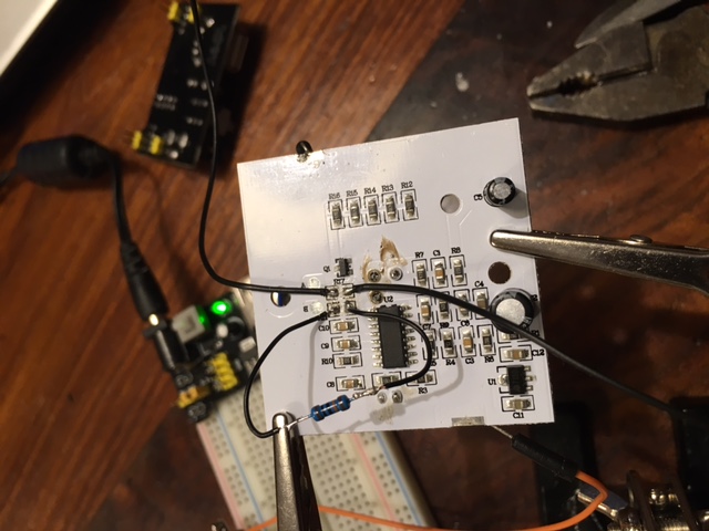
    Inside there is a PIR in combination with 5 leds and a photodiode. As soon as it gets dark the PIR is active and as soon as movement is detected the leds are switched on for about 30 sec.
    The IKEA PIR is based on BIS0001 chip, which is a very common chip. When High it has an output of about 1,8 volt. Via a transistor the leds are switch on. Although there are three batteries in the housing the PIR runs also very well on two. (3.3 volt)


  • @TimO Yes if have read this post too, but here he has used an optocoupler. Which is not necessary if you reduce the input to 3 volt... makes it more easy. Or even use the 1,8 volt as input. But don't short circuit it with the input pin next to it.... as the PIR will stay high forever.😈
    0_1461769323939_PIR1.jpg
    0_1461769341400_PIR2.jpg


  • Hardware Contributor

    @dynamite
    nice clean hack 🙂
    Could you tell me what is the overall thickness please? I think I will try to buy one just to see how fit some of my multisensors boards inside..even if i will use 3d printing which cost less $ in plastic, it's still a very nice alternative to have at hand.
    Maybe you could use some i2c sensors to improve your power consumption.
    Thx for your share 😉


  • Mod

    @dynamite Great hack!
    Especially when using the combination of original PIR, enclosure and battery holder for E 5,-.
    Can't be beaten! 👍


  • @Yveaux And very easy to detach as it has a base plate as well...
    0_1461770137513_ikea1.jpg


  • @scalz What dimensions are you exactly looking for?
    Here you have some photos:
    1_1461770194862_ikea4.jpg 0_1461770194861_ikea3.jpg


  • Hardware Contributor

    @dynamite awesome, thx 🙂
    oh no, please no more pics 😋 lol it's very cool hack 😍


  • Admin

    Think I have to visit ikea tomorrow, and bring home a couple of samples 🙂

    Only about 5$...


  • @tbowmo I think I am going to buy some IKEA shares....😀


  • Hardware Contributor

    7€ here...french conversion 😠
    it's at one hour from my home..but I think I will visit too this weekend. well done, now I can't wait 🙂


  • @scalz @tbowmo Looking forward to see you results! Now that my prototype is finished of course I am going to buy some more as well. Here "only" €4,99 for an item


  • Hi,
    is it possible to describe, how to wire the original PIR, with the Arduino?

    I have some Molgan's here and want to mod them, if i can use the original PIR, it would be perfect 🙂

    Maybe an HowTo?

    Many Thanks


  • @Floca hi the Original Ikea Pir, I kind of destroyed during the "investigation". I my previous post I have posted a picture of the pir inside. I would feed the pir with either 2 or 3 batteries. (3/4,5v) after that you can either use the signal directly after the chip. Th is is 1,8v but I don't know if the arduino takes that as high..? If not you can take the signal at the resistors of the LEDs. The voltage level here is depending on your battery infeed. So either 3v or 4,5v. Don't think both will be a problem for the arduino. To eliminate the led you can take away one or more resistors.
    Maybe somebody can say more
    About the allowable Voltage levels. For battery live a 3v pro mini would be better. For ease of use a 5v version would be better


  • After I have bought some new one I will try to make a how to....


  • PLEASE! A How to would be amazing! Looking forward to it!


  • I now have a fresh supply of Molgan to be modified. And I will post my modification of the existing board soon. Status I can now use the input of the existing PIR signal. And I have discovered that by sending out a high or low on one of the arduino pins I can switch the existing LED on / off. Of course I can use a relay function to control but as it is running on batteries the sensor has to sleep. I was thinking of sending out a parameter (true / false) which enables the sensor to activate the LED on a trigger of the PIR. How could I send over this parameter? Any (creative) idea's as the sensor is sleeping most of the time?

    Now I am thinking of it, could it be possible that such a value is read by the sensor when the sensor is getting out of the sleep function.


  • Cool can´t wait for this,have bought 6 Molgans last week 👍


  • @Didi Nice, I only bought four ....😃


  • In development branch there is a smartsleep function for receiving while sleeping (if I get it right)


  • @rollercontainer I could use the wait function
    /**

    • Wait for a specified amount of time to pass or until specified message received. Keeps process()ing.
    • This does not power-down the radio nor the Arduino.
    • Because this calls process() in a loop, it is a good way to wait
    • in your loop() on a repeater node or sensor that listens to messages.
    • @param ms Number of milliseconds to sleep.
    • @param cmd Command of incoming message.
    • @param msgtype Message type.
      */
      void wait(unsigned long ms, uint8_t cmd, uint8_t msgtype);

    And wait for a message, which is send out by the controller (by a rule) after receiving the PIR trigger. But it is a kind of waste of energy to wait for a signal which is not frequently used. As far as I can read in the code this is exactly what smart sleep does. But can how can prepare a reply by the gateway that will respond to such a heartbeat?


  • 0_1464292606824_IMG_5287.JPG
    It is unfortunately not a full How-To yet. But basically the IKEA PIR is ready for operation.

    • The PIR Runs on 3 Volt. There is a power regulator (U1). I am going to keep the 3 AAA batteries so I keep the regulator on the board.

    • I have removed the resistor (R17) and attached two wires to both the Original ends on the board. The one closest to the BISS0001 is your PIR signal. 3V when high and 0V for low. The other wire can be used to control the lights on the board. The wire is connected to the Q1 NPN transistor. Basically 3V high is on and 0V is off. But maybe you will also be able to dim the lights.

    • You also need to remove Resistor R11. The Original value is about 620 K and this will result in 30 seconds of ON after triggering. I have replaced it with 100 K and now it is about 5 seconds, a further reduction whill shorten this time lineair. So 10K = 0,5 sec. The PIR itself is retriggered.

    • With resistor R10 is controlling the time that the PIR cannot be triggered after a trigger. It is now approx 10K = 0,5 sec. So no need to change.

    • You need also to remove the photodiode on the front. Otherwise the PIR is only triggered when it is dark.

    • The powerconsumption of the PIR when not triggered is approx. 60 uA and when triggered 160 uA. So this is about the same as the standard PIR's. When the lights are activated the consumption is about 36 mA.

    • The PIR (without the hood) is quite sensitive. Even the slightest movement is already triggering the PIR.


  • Mod

    @dynamite Nice work!
    I'm currently working on the following Molgan hack:
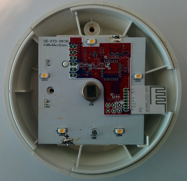
    0_1464446092298_2016-05-15 12.30.57.jpg

    It is a small PCB (the red board) that overlays the original Molgan PCB.
    The original PIR & electronics stay in place.
    LEDs will remain functional (if you want) or can be partially removed to improve battery life, or completely to turn it into a motion-sensor only.
    It uses an SMD nRF24 module, has a mounting spot for SHA204A, FTDI and ISP connectors.

    The layout is currently at the board house.
    I'll report back when I get the PCBs and build one!


  • @Yveaux NICE! Can I get the files for the board as a sneak preview? Do you get the PIR signal / Light control from the same place as I was indicating?


  • Mod

    @dynamite Send me your email in a chat and it comes your way.
    I'll probably post it all on openhardware.io when it's finished and proven to work.
    Fun thing is I tried the power usage of the original PIR with and without the regulator, and the power usage was actually less with the regulator than without 😋
    I'll use two of the three batteries to also power my addon board.
    The trigger is taken from the top led, just below the battery cover screw in the picture.
    I could take it from before the transistor, but this way I needed no extra wire.


  • @Yveaux Sent you a DM with my email adress. Can't you use the voltage level after the regulator? The regulator is rated up to 30 mA.


  • Mod

    @dynamite Possibly. I just wanted to keep options open.
    One wire is required to power the board; either from the batteries, or from the regulator.
    I'll just see what works best.


  • Admin

    This have to be posted on http://www.ikeahackers.net/ when done also.


  • Mod

    @hek Will do just nice, next to the AK47 Hemma Lamp 😳


  • @Yveaux @hek how do you know of the existance of such a site...?😦


  • Mod

    @dynamite I didn't. Got it from @hek :bowtie:


  • Did someone succeed in fitting a pro mini and radio in the Molgan while still using the original pir?
    It looks to me there isn't enough room for the additional components and I'm not sure what part of the pcb I can saw off while still being able to use the original pir.

    Does anyone have an idea?


  • @danta 0_1464637700422_image.jpeg
    Fits.... Ok i need to attach the wites but it will still fit. The NRF can be placed on the other side


  • Bought 3 pcs. to open / modify / try fitting things in it. The thing is that this housing is really perfect to place it on the ceiling or to fit things in. Better than a black box.
    What I'm going to try is remove all the plastic inside including the batteryhousing but not the "click"-system to mount it.
    I'm going to try to make it 230 volt compatible with a HLK-PM01 so that I can use it as a PIR, Temp and door sensor and connect it at the ceiling.

    Let you know how things are working out!


  • Mod

    @Sander-Stolk said:

    door sensor and connect it at the ceiling

    ???
    My house has its doors in the walls...


  • @Yveaux said:

    @Sander-Stolk said:

    door sensor and connect it at the ceiling

    ???
    My house has its doors in the walls...

    Well... connect a very small white wire in the hallway to the top of the door with a magnet.
    With white ceilings you can put little cables like out of sight


  • Mod

    @Sander-Stolk ah, OK. I think you can even run it all on batteries if you want


  • @Yveaux Yes it can BUT...
    I have 0 succesfull attempts with a APM with removed regulator on 2 AA batteries. For some reason it draws power and within 3 days my batteries are dead. It's something that I will ask on the forum in a while but for now this works all the time so for it is the easy way 🙂


  • Here is my a picture of my modded version alt text. I used a Sensebender which is perfect for that use case having already a ATSHA204 and temp/humid sensor on board.


  • I put a more complete write up of my mod from the previous post on my blog including the link to the sketch.


  • @tomkxy Nice write up of the "conversion". One remark to save some time... instead of removing R12 to R16 you can just remove R17 ... same result less effort.


  • @dynamite said:

    @tomkxy Nice write up of the "conversion". One remark to save some time... instead of removing R12 to R16 you can just remove R17 ... same result less effort.

    Thanks for pointing that out!


  • Hero Member

    @tomkxy Nice write up! Do you have an idea on the accuracy of the humidity sensor within the case?


  • @TimO said:

    @tomkxy Nice write up! Do you have an idea on the accuracy of the humidity sensor within the case?

    I just put it up in my one of my rooms. It works at least at a distance of about 4m. I will try to do some measure at what distance it is working. I'll post the results.


  • @TimO said:

    @tomkxy Nice write up! Do you have an idea on the accuracy of the humidity sensor within the case?

    Sorry, just saw that you asked about the humidity sensor. No, I have no idea yet. Need to make some comparison measures.


  • Hero Member

    @tomkxy did you really need the voltage divider? I think the sensebender does a decent job of measuring battery percentage by default.


  • @korttoma As far as I can see the sensebender is fed by the 3 volt of the PIR. So you can not use this as a reference for voltage measurement.


  • @TimO @tomkxy I have the Dallas sensor within the case. The reading follows the same line as other temp sensors within the same room. No big delay or something. The only downside is that the PIR is mounted on the roof, so temp is always a bit higher.


  • I just realized that I see a lot of false triggers. Anybody else having that experience? Any idea how sensitivity of the PIR can be reduced?


  • @tomkxy You can change the sensitivity of the PIR. You have to change the value or R15. See here for a datasheet of the BISS001
    But I do not know whether you should increase or decrease it...?
    If you did not modify your PIR then the PIR will stay high for 30 SEC. What is the period between the false triggers?
    Could it have to do with powering your sensebender from the powersource within the PIR and not directly from the battery?


  • @dynamite I see no clear pattern for the false triggers. Most of the time it is after about 7 minutes. But not strictly. Sometimes more than a half hour.. Well if I would power the sense bender directly from the battery I either would have to use a regulator or remove one of the batteries. Would the PIR still work reliable with about 2.4V? Would it make sense to try a capacitor between the 3V where I power the sense bender from to ground?


  • @tomkxy The range of PIR is 3-5V so most probably 2.4 V will give some trouble.


  • Mod

    @tomkxy you can just use 3 batteries to power the pir and only 2 to power the atmega and radio. Just c
    Use the same ground on them, and tap the arduino power after the second battery.
    I have some pirs running this way and they work just fine!


  • @Yveaux @tomkxy You were one step ahead of me, I was just thinking of that solution. At the moment I am also preparing version 2 of the MOLGAN PIR based on Arduino pro Mini I will check on the false positives as well. But I will feed both the PIR and pro Mini directly from the three batteries.


  • @Yveaux @dynamite Thanks for your suggestion. I followed @Yveaux suggestion and tapped the power for the sensebender after the second battery. It is now working for 2 hours without any false triggers. I will continue the test (for test purposes the sensor is sitting in a room with usually has no movement).


  • Mod

    @tomkxy 👍
    The same setup is working fine for me for quite a long time now!


  • @Yveaux Unfortunately, I still get false triggers. Do you also use a sensebender? Any ideas, what I can try. I tapped into as you suggested to the second battery.


  • Mod

    @tomkxy I have some ProMini's (8Mhz) with regulator bypassed which are 2xAA fed in this way.
    The PIRs are HC-SR501's, also with the regulator removed and 3xAA fed.
    I haven't tested this setup on the Molgan's yet, but assuming the IC's are both BISS0001 I expect results to be identical.

    Here's a picture of my setup:

    0_1465748316875_20160328-160217.jpg

    (Btw. components on the HC-SR501 have been moved to the side to decrease the unit's depth)


  • Mod

    FYI, I measured power comsumption on the Mogan when sleeping with and without regulator.
    The power consumption was significantly less with the voltage regulator, then when directly powered from 3xAAA (regulator removed).
    Therefore, my Molgan hack board design targets to use the PIR with regulator (3xAAA input) and the ATmega+nRF powered directly from 2xAAA.


  • @tomkxy I Will put mine for a test run online tonight in the closet. If no trigger than it should be ok.
    Edit: did something wrong when removing led from pro mini so some debugging is required.... No testing tonight 😢


  • I googled a bit regarding PIR false alarms and found a couple of links. Apart from small bugs - which I have not in the room - air vents could trigger false alarms. Thus, I put back the plastic dome and now have sind 4 hours no false alarms. I am now convinced that my false alarms a most probably triggered by placement and may be air vents.

    http://de.actmeters.com/advice/five-causes-of-pir-false-alarms/
    https://www.youtube.com/watch?v=h0bp91xy5vY
    http://www.hkvstar.com/technology-news/how-to-install-pir-sensor-minimize-the-false-alarm.html


  • Mod

    @tomkxy of course you should always mount the fresnel cover. It focuses the incoming IR on the sensor and forms a barrier. Without the cover the sensor will always be more sensitive and have a much smaller field of view, increasing sensitivity even more.
    If an unmodified Molgan doesn't suffer from false triggers, a modified one also shouldn't.

    This is one more confirmation of the importance of describing your setup accurately 😏


  • I made a couple of additional modifications based on posts here and google results:

    • put a short wait before the node goes to sleep -> based on reports from that forum
    • read the motion pin twice with a small wait in between
    • put a small alu foil between the radio and the PCB -> there are some reports in the internet that RF interference could cause false triggers

    I had a close look at the sensor today and everything looked okay so far. However, I was moving into the room in and out. Let's see what the result tomorrow will be.


  • @TimO said:

    @tomkxy Nice write up! Do you have an idea on the accuracy of the humidity sensor within the case?

    I did some comparison measure regarding temp and humidity. I place an open Sensebender just beside the modded Molgan. The humidity measured at the Molgan was about 11% lower than the humidity measured by the open Sensebender. With respect to temp the Molgans temp was about 6% lower than the temp measured by the open Sensebender.


  • Hero Member

    @tomkxy Thank you for reporting back!


  • Ok, so if I as a complete beginner want to use a the original pir and control the lights all I need to do is:

    Tap the power from the regulator U1 and power a 3.3v mini-pro (keeping the 3 batteries)

    Remove Resistor R17 and connect the solderpoint nearest the chip to an arduino input and I can then basicly be able to run the standard motion sketch ? (After removing the photodiode and bridging the connectors?)

    I can connect the the other solderpoint to an arduino output and if uploading a sketch witch puts that output HIGH the leds will turn on?

    If I am fine with 30secs of triggertime I do not have to do anything more?

    Are all my assumptions correct?


  • @Cliff-Karlsson correct!😄


  • @Cliff-Karlsson
    Excellent summarized! Perfect HowTo!

    Voted Cliff-Karlson for Documentation Team 😄


  • Haha, right. Last question, if I also want the sensor to report battery-usage. Is there any way to accomplish that without soldering any more resistors?


  • Mod

    @Cliff-Karlsson Yes, there is!
    Use my Vcc library!


  • @Yveaux @Cliff-Karlsson but in the scheme of cliff he is taken the power after the power regulator. So you are not
    Measuring the battery with your VCC library.


  • Mod

    @dynamite You're right then. I didn't read his howto, just answered how to read battery voltage without voltage divider 😉


  • Ok, but if I measured right when talking the power from the regulator you could get 3v or ~4.5v witch i guess is directly from the batteries. If I connect the 4.5v to the power input on the same side as the tx/rx can I still not use the vcc library?


  • How would a sketch for this PIR look like? I tried combining the PIR and RelayActuator but my skills are not enough.

    This is what I have came up with:

    /**
     * The MySensors Arduino library handles the wireless radio link and protocol
     * between your home built sensors/actuators and HA controller of choice.
     * The sensors forms a self healing radio network with optional repeaters. Each
     * repeater and gateway builds a routing tables in EEPROM which keeps track of the
     * network topology allowing messages to be routed to nodes.
     *
     * Created by Henrik Ekblad <henrik.ekblad@mysensors.org>
     * Copyright (C) 2013-2015 Sensnology AB
     * Full contributor list: https://github.com/mysensors/Arduino/graphs/contributors
     *
     * Documentation: http://www.mysensors.org
     * Support Forum: http://forum.mysensors.org
     *
     * This program is free software; you can redistribute it and/or
     * modify it under the terms of the GNU General Public License
     * version 2 as published by the Free Software Foundation.
     *
     *******************************
     *
     * REVISION HISTORY
     * Version 1.0 - Henrik Ekblad
     * 
     * DESCRIPTION
     * Motion Sensor example using HC-SR501 
     * http://www.mysensors.org/build/motion
     *
     */
    
    // Enable debug prints
    #define MY_DEBUG
    
    // Enable and select radio type attached
    //#define MY_RADIO_NRF24
    #define MY_RADIO_RFM69
    
    #include <SPI.h>
    #include <MySensors.h>
    
    unsigned long SLEEP_TIME = 120000; // Sleep time between reports (in milliseconds)
    #define DIGITAL_INPUT_SENSOR 3   // The digital input you attached your motion sensor.  (Only 2 and 3 generates interrupt!)
    #define RELAY_1  9  // Arduino Digital I/O pin number for first relay (second on pin+1 etc)
    #define NUMBER_OF_RELAYS 1 // Total number of attached relays
    #define RELAY_ON 1  // GPIO value to write to turn on attached relay
    #define RELAY_OFF 0 // GPIO value to write to turn off attached relay
    
    
    #define CHILD_ID 1   // Id of the sensor child
    #define SECONDARY_CHILD_ID 4
    
    void before() { 
      for (int sensor=1, pin=RELAY_1; sensor<=NUMBER_OF_RELAYS;sensor++, pin++) {
        // Then set relay pins in output mode
        pinMode(pin, OUTPUT);   
        // Set relay to last known state (using eeprom storage) 
        digitalWrite(pin, loadState(sensor)?RELAY_ON:RELAY_OFF);
      }
    }
    
    // Initialize motion message
    MyMessage msg(CHILD_ID, V_TRIPPED);
    
    void setup()  
    {  
      pinMode(DIGITAL_INPUT_SENSOR, INPUT);      // sets the motion sensor digital pin as input
      
      
    }
    
    void presentation()  {
      // Send the sketch version information to the gateway and Controller
      sendSketchInfo("Light/Motion Sensor ikea", "1.0");
    
      // Register all sensors to gw (they will be created as child devices)
      present(CHILD_ID, S_MOTION);
      for (int sensor=1, pin=RELAY_1; sensor<=NUMBER_OF_RELAYS;sensor++, pin++) {
        // Register all sensors to gw (they will be created as child devices)
        present(sensor, S_LIGHT);
    }
    
    void loop()     
    {     
      // Read digital motion value
      boolean tripped = digitalRead(DIGITAL_INPUT_SENSOR) == HIGH; 
            
      Serial.println(tripped);
      send(msg.set(tripped?"1":"0"));  // Send tripped value to gw 
    
      // Sleep until interrupt comes in on motion sensor. Send update every two minute.
      sleep(digitalPinToInterrupt(DIGITAL_INPUT_SENSOR), CHANGE, SLEEP_TIME);
    }
    
    void receive(const MyMessage &message) {
      // We only expect one type of message from controller. But we better check anyway.
      if (message.type==V_LIGHT) {
         // Change relay state
         digitalWrite(message.sensor-1+RELAY_1, message.getBool()?RELAY_ON:RELAY_OFF);
         // Store state in eeprom
         saveState(message.sensor, message.getBool());
         // Write some debug info
         Serial.print("Incoming change for sensor:");
         Serial.print(message.sensor);
         Serial.print(", New status: ");
         Serial.println(message.getBool());
      }
      }
    

    But it does not complie after the last part is added. And I would also like to get the vcc -stuff into the same sketch. Could someone post a working sketch for this?


  • @Cliff-Karlsson you can only use the VCC sketch if you by pass the voltage regulators. So power the arduino from two batteries by a separate wire.


  • @Cliff-Karlsson the receive routine is out of the repeat loop


  • Ok, tried placing it in the loop to but with the same result. In the RelayActuator it looks like it really is placed outside the loop: RelayActuator

    What would the prefered way be to connect the power to the a 3.3v arduino for the best battery time?

    4.5v from the PIR regulator --> Arduino RAW (using 3 batteries)
    3v from the PIR regulator --> Arduino VCC (3batteries)

    And how would I power it from only 2 batteries? would not the PIR or leds need higher voltage than 3v ?


  • Mod


  • Hi guys,

    I'm struggling with this one unfortunately, i can't get it to trip/untrip.

    Sketch is identical to the motion example.

    I've removed the photo diode (not bridged the gap, it looks like bridging the gap stops it from tripping at all, leaving it open means it trips whatever the light level is). This was tested without connecting to the arduino, working as normal.

    So i've removed resistor 17, and connected my arduino pin 4 up to the chip side of where R17 was. I'm running the main board of the existing power lines, but i've tapped into the + of the middle battery and that's going to VCC on the arduino. Arduino nano GND is connected to the main board -.

    Where am I going wrong? I've tried this on two boards now and they're both acting the same. Serial monitor is just showing me:

    send: 14-14-4-0 s=1,c=1,t=16,pt=0,l=1,sg=0,st=ok:1
    1
    send: 14-14-4-0 s=1,c=1,t=16,pt=0,l=1,sg=0,st=ok:1
    1
    send: 14-14-4-0 s=1,c=1,t=16,pt=0,l=1,sg=0,st=ok:1
    1

    Thanks,

    Patrick


  • @pjblink hi your setup sounds ok to me! And from your debug I think it is transmitting a value. Is this value submitted after activating the pir?
    After activation the is high for about 30 sec then it sound be low again. Maybe you can verify this procedure. Can you debug on the receiving side?


  • I have build a couple of these and they work fine. Replacing batteries with the baseplate is really a huge advantage, and battery life seems to be pretty good.

    I have one issue though: I have built one including an LDR. But this seems to freeze after a random time, no longer reacting to movement.
    @dynamite , can you may be share your code and the way you have attached your LDR to the arduino etc?

    Many thanks!


  • @gijss Hi I will try to find the code tonight and post it on github.


  • Guys,

    This is fantastic. Can someone summarise the best practises for using an Arduino Pro mini, to benefit from maximum battery life and voltage monitoring?

    Thank you!


  • Mod

    @Mark-Swift https://www.mysensors.org/build/battery has information on how to get good battery life


  • @dynamite , can you may be share your code and the way you have attached your LDR to the arduino etc?

    @gijss the code can be found here. But I don't know the actual status of this code as I have not used it for a while and I was busy creating a dimmer. But maybe you can copy parts out of it.

    https://github.com/rspaargaren/My-sensors-IKEA/blob/master/multisensor.ino


  • @dynamite said:

    @gijss the code can be found here. But I don't know the actual status of this code as I have not used it for a while and I was busy creating a dimmer. But maybe you can copy parts out of it.

    https://github.com/rspaargaren/My-sensors-IKEA/blob/master/multisensor.ino

    @dynamite Thanks for the code, I am sure it will prove to be useful. Will try to experiment this weekend. Can you also share how you connected the LDR to the arduino? I have the feeling I might be using a suboptimal wiring scheme (or wrong resistor) resulting in shorter battery life.


  • @Yveaux Did you finish the PCB for the molgan?, If so is it possible for you to share the files?


  • Hardware Contributor

    I would be interested too!


  • Mod

    @Cliff-Karlsson Yes, works like a charm!
    It has been on my ToDo list for quite a long time to publish the files -- please hold on a little longer 😉


  • @Yveaux great as my project was on hold for a while but still on the to do list...:-)


  • Mod

    @Cliff-Karlsson @LastSamurai @dynamite I just published the PCB on [OpenHardware.io].(https://www.openhardware.io/view/274/Ikea-Molgan-Hack)
    A sketch will follow soon.

    Enjoy!


  • @dynamite

    It has been a while (mainly because the PIR was out of order for other reasons) but now I am restarting the project and again it happened that the PIR no longer responded. So I took a look at your code, but it seems your are using a BH1750 light sensor, is that correct? And are you using that in fact at the moment, or did you switch to LDR and is this perhaps not the latest version of the code?

    Thanks!

    Gijss


  • @gijss Hi let me check upon that as the PIR has not been on the top of my priority list. I have one of the PIR based on LDR sensor. But I was working on a BH1750 sensor. So most probably the code is related to that version.


  • Hi to all,
    I've realized my hacked version of the Ikea Molgan but the PIR sensor stays always HIGH.
    Everything works apart of this... Do you have any idea howto investigate?

    could I have broken it?


  • @ricmail85 hi iT has been a while ago but as far as I recollect I had the same problem with one of my sensors ...

    In normal situation the sensors gives a high signal for approx 30 sec.

    In the bricked PIR I have replace the pir board by a cheap and modified pir from Ali.


  • Ok thanks for your reply. I'll check the board for some weak connection and try again...
    bye!


  • Mod

    @ricmail85 I also have one Molgan that I just can't get to work correctly. Put it aside, thinking it was an incident, but if more people have issues, this might be a structural thing...


  • @Yveaux said in Multisensor PIR based on IKEA Molgan:

    @ricmail85 I also have one Molgan that I just can't get to work correctly. Put it aside, thinking it was an incident, but if more people have issues, this might be a structural thing...

    I'll give it a try. I have to check that the wires I soldered on the back of the breadboard are just fine...
    I'll let you know.

    bye!


Log in to reply
 

Suggested Topics

  • 8
  • 29
  • 3
  • 2
  • 1
  • 2

0
Online

11.2k
Users

11.1k
Topics

112.5k
Posts