Multisensor PIR based on IKEA Molgan
-
@tomkxy you can just use 3 batteries to power the pir and only 2 to power the atmega and radio. Just c
Use the same ground on them, and tap the arduino power after the second battery.
I have some pirs running this way and they work just fine! -
@Yveaux @dynamite Thanks for your suggestion. I followed @Yveaux suggestion and tapped the power for the sensebender after the second battery. It is now working for 2 hours without any false triggers. I will continue the test (for test purposes the sensor is sitting in a room with usually has no movement).
-
@Yveaux Unfortunately, I still get false triggers. Do you also use a sensebender? Any ideas, what I can try. I tapped into as you suggested to the second battery.
@tomkxy I have some ProMini's (8Mhz) with regulator bypassed which are 2xAA fed in this way.
The PIRs are HC-SR501's, also with the regulator removed and 3xAA fed.
I haven't tested this setup on the Molgan's yet, but assuming the IC's are both BISS0001 I expect results to be identical.Here's a picture of my setup:
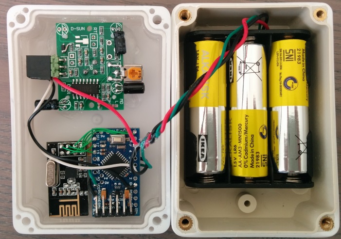
(Btw. components on the HC-SR501 have been moved to the side to decrease the unit's depth)
-
FYI, I measured power comsumption on the Mogan when sleeping with and without regulator.
The power consumption was significantly less with the voltage regulator, then when directly powered from 3xAAA (regulator removed).
Therefore, my Molgan hack board design targets to use the PIR with regulator (3xAAA input) and the ATmega+nRF powered directly from 2xAAA. -
@Yveaux Unfortunately, I still get false triggers. Do you also use a sensebender? Any ideas, what I can try. I tapped into as you suggested to the second battery.
-
I googled a bit regarding PIR false alarms and found a couple of links. Apart from small bugs - which I have not in the room - air vents could trigger false alarms. Thus, I put back the plastic dome and now have sind 4 hours no false alarms. I am now convinced that my false alarms a most probably triggered by placement and may be air vents.
http://de.actmeters.com/advice/five-causes-of-pir-false-alarms/
https://www.youtube.com/watch?v=h0bp91xy5vY
http://www.hkvstar.com/technology-news/how-to-install-pir-sensor-minimize-the-false-alarm.html -
I googled a bit regarding PIR false alarms and found a couple of links. Apart from small bugs - which I have not in the room - air vents could trigger false alarms. Thus, I put back the plastic dome and now have sind 4 hours no false alarms. I am now convinced that my false alarms a most probably triggered by placement and may be air vents.
http://de.actmeters.com/advice/five-causes-of-pir-false-alarms/
https://www.youtube.com/watch?v=h0bp91xy5vY
http://www.hkvstar.com/technology-news/how-to-install-pir-sensor-minimize-the-false-alarm.html@tomkxy of course you should always mount the fresnel cover. It focuses the incoming IR on the sensor and forms a barrier. Without the cover the sensor will always be more sensitive and have a much smaller field of view, increasing sensitivity even more.
If an unmodified Molgan doesn't suffer from false triggers, a modified one also shouldn't.This is one more confirmation of the importance of describing your setup accurately :smirk:
-
I made a couple of additional modifications based on posts here and google results:
- put a short wait before the node goes to sleep -> based on reports from that forum
- read the motion pin twice with a small wait in between
- put a small alu foil between the radio and the PCB -> there are some reports in the internet that RF interference could cause false triggers
I had a close look at the sensor today and everything looked okay so far. However, I was moving into the room in and out. Let's see what the result tomorrow will be.
-
@tomkxy Nice write up! Do you have an idea on the accuracy of the humidity sensor within the case?
@TimO said:
@tomkxy Nice write up! Do you have an idea on the accuracy of the humidity sensor within the case?
I did some comparison measure regarding temp and humidity. I place an open Sensebender just beside the modded Molgan. The humidity measured at the Molgan was about 11% lower than the humidity measured by the open Sensebender. With respect to temp the Molgans temp was about 6% lower than the temp measured by the open Sensebender.
-
Ok, so if I as a complete beginner want to use a the original pir and control the lights all I need to do is:
Tap the power from the regulator U1 and power a 3.3v mini-pro (keeping the 3 batteries)
Remove Resistor R17 and connect the solderpoint nearest the chip to an arduino input and I can then basicly be able to run the standard motion sketch ? (After removing the photodiode and bridging the connectors?)
I can connect the the other solderpoint to an arduino output and if uploading a sketch witch puts that output HIGH the leds will turn on?
If I am fine with 30secs of triggertime I do not have to do anything more?
Are all my assumptions correct?
@Cliff-Karlsson correct!:smile:
-
Ok, so if I as a complete beginner want to use a the original pir and control the lights all I need to do is:
Tap the power from the regulator U1 and power a 3.3v mini-pro (keeping the 3 batteries)
Remove Resistor R17 and connect the solderpoint nearest the chip to an arduino input and I can then basicly be able to run the standard motion sketch ? (After removing the photodiode and bridging the connectors?)
I can connect the the other solderpoint to an arduino output and if uploading a sketch witch puts that output HIGH the leds will turn on?
If I am fine with 30secs of triggertime I do not have to do anything more?
Are all my assumptions correct?
@Cliff-Karlsson
Excellent summarized! Perfect HowTo!Voted Cliff-Karlson for Documentation Team :-D
-
Haha, right. Last question, if I also want the sensor to report battery-usage. Is there any way to accomplish that without soldering any more resistors?
-
Haha, right. Last question, if I also want the sensor to report battery-usage. Is there any way to accomplish that without soldering any more resistors?
@Cliff-Karlsson Yes, there is!
Use my Vcc library!http://yveaux.blogspot.nl
-
@Cliff-Karlsson Yes, there is!
Use my Vcc library! -
@Yveaux @Cliff-Karlsson but in the scheme of cliff he is taken the power after the power regulator. So you are not
Measuring the battery with your VCC library. -
Ok, but if I measured right when talking the power from the regulator you could get 3v or ~4.5v witch i guess is directly from the batteries. If I connect the 4.5v to the power input on the same side as the tx/rx can I still not use the vcc library?