Skip to content
  • MySensors
  • OpenHardware.io
  • Categories
  • Recent
  • Tags
  • Popular
Skins
  • Light
  • Brite
  • Cerulean
  • Cosmo
  • Flatly
  • Journal
  • Litera
  • Lumen
  • Lux
  • Materia
  • Minty
  • Morph
  • Pulse
  • Sandstone
  • Simplex
  • Sketchy
  • Spacelab
  • United
  • Yeti
  • Zephyr
  • Dark
  • Cyborg
  • Darkly
  • Quartz
  • Slate
  • Solar
  • Superhero
  • Vapor

  • Default (No Skin)
  • No Skin
Collapse
Brand Logo
  1. Home
  2. Troubleshooting
  3. NRF24L01+PA+LNA power consumption

NRF24L01+PA+LNA power consumption

Scheduled Pinned Locked Moved Troubleshooting
53 Posts 9 Posters 25.9k Views 9 Watching
  • Oldest to Newest
  • Newest to Oldest
  • Most Votes
Reply
  • Reply as topic
Log in to reply
This topic has been deleted. Only users with topic management privileges can see it.
  • OitzuO Oitzu

    Hi @parachutesj,

    you should test it with a loop sending data. It has the highest consumption while sending data.
    Seeing your PA/LNA you should also shield it, to extend range.

    parachutesjP Offline
    parachutesjP Offline
    parachutesj
    wrote on last edited by
    #4

    @Oitzu
    I tried it with sending a lot of packets but still, no more current than before. Are there any specific settings I need to do for the PA radio?

    1 Reply Last reply
    0
    • OitzuO Offline
      OitzuO Offline
      Oitzu
      wrote on last edited by
      #5

      @parachutesj: expect the RF24_PA_MAX no. I need to say that i still use the 1.5 library and set the PA_MAX setting in the MyConfig.h.

      parachutesjP 1 Reply Last reply
      1
      • OitzuO Oitzu

        @parachutesj: expect the RF24_PA_MAX no. I need to say that i still use the 1.5 library and set the PA_MAX setting in the MyConfig.h.

        parachutesjP Offline
        parachutesjP Offline
        parachutesj
        wrote on last edited by
        #6

        @Oitzu thank you. tried this as well with no difference. I suspect my radios are really bad. I got much better results with the non amplified ones during testing. I think I will try if they perform better with a LC filter if not, good bye

        1 Reply Last reply
        0
        • OitzuO Offline
          OitzuO Offline
          Oitzu
          wrote on last edited by
          #7

          @parachutesj you probably don't benefit from a LC-Filter that much, because you are already using a linear regulator (LD1117 ).
          Make sure that you used the shielding right and grounded it.

          1 Reply Last reply
          0
          • JokgiJ Offline
            JokgiJ Offline
            Jokgi
            wrote on last edited by
            #8

            What is the PA used on the board? Are there schematics available? (Or a part number for the board) Are they using the VDD_PA line from the nRF24L01P to enable the PA? If so, scope out the VDD_PA line and see if it is toggling when transmitting. It will go high 50us before the nRF24L01p transmits a packet and will stay high the full time it is transmitting. If that line is not toggling when sending packets then you are not transmitting.

            parachutesjP 1 Reply Last reply
            0
            • OitzuO Offline
              OitzuO Offline
              Oitzu
              wrote on last edited by
              #9

              @Jokgi: https://www.squirrel-labs.net/wp/wp-content/uploads/2015/02/nRFa.jpg
              I think that is what most of the boards are doing. But i also seen schematics in wich the 1kOhm resistor isn't there.
              So there could maybe be problems if you try to control the nrf24l01+ PA/LNA with a 5V Arduino because the PA can't handle the 5V signal.

              JokgiJ 1 Reply Last reply
              0
              • OitzuO Oitzu

                @Jokgi: https://www.squirrel-labs.net/wp/wp-content/uploads/2015/02/nRFa.jpg
                I think that is what most of the boards are doing. But i also seen schematics in wich the 1kOhm resistor isn't there.
                So there could maybe be problems if you try to control the nrf24l01+ PA/LNA with a 5V Arduino because the PA can't handle the 5V signal.

                JokgiJ Offline
                JokgiJ Offline
                Jokgi
                wrote on last edited by
                #10

                @Oitzu
                Is that the released schematic for that Module?
                I can see why they have the resistor removed.
                The CE line is a active high input to the nRF24L01P. The RXEN is a input to the RFX2401C used to switch in the different modes. (See the mode select table below)
                The CE line could / should be controlled by the host MCU. You can see this on the state machine in the nRF24L01P datasheet section 6.1.1, Figure 4. The diagram shows recommended operating modes vs. possible operating modes.

                For the RFX2401C,,,,
                If the RXEN is pulled high with a resistor and when the nRF24L01P is not transmitting, the unit will switch the LNA in. In this setup the RFX never goes to shut down mode and the RFX is either in TX or RX mode. There are no internal pull ups or pull downs on the nRF24L01P CE or or the RFX devices RXEN. Therefore there is no guaranty that the lines will be high or low and could be subject to noise. I would not leave them floating.

                Control Logic Truth Table X= Don't Care
                TXEN RXEN 0perating Conditions
                1 X TX Active
                0 1 RX Active
                0 0 Chip is Shut-down

                To address the Current Draw. According to the RFX2401C datasheet, when the PA is transmitting at 20dBm the current consumption of the amp is 120mA. Plus whatever else you have running. (MCU, nRF24L01P, etc)

                1 Reply Last reply
                0
                • JokgiJ Jokgi

                  What is the PA used on the board? Are there schematics available? (Or a part number for the board) Are they using the VDD_PA line from the nRF24L01P to enable the PA? If so, scope out the VDD_PA line and see if it is toggling when transmitting. It will go high 50us before the nRF24L01p transmits a packet and will stay high the full time it is transmitting. If that line is not toggling when sending packets then you are not transmitting.

                  parachutesjP Offline
                  parachutesjP Offline
                  parachutesj
                  wrote on last edited by
                  #11

                  @Jokgi
                  Thank you. I am using this http://rover.ebay.com/rover/1/711-53200-19255-0/1?icep_ff3=2&pub=5575069610&toolid=10001&campid=5337433187&customid=&icep_item=310651702557&ipn=psmain&icep_vectorid=229466&kwid=902099&mtid=824&kw=lg

                  Datasheet link is broken...

                  1 Reply Last reply
                  0
                  • OitzuO Offline
                    OitzuO Offline
                    Oitzu
                    wrote on last edited by
                    #12

                    @Jokgi hard to say to which module excatly it belongs.. would need to track the traces on the pcb to be 100% sure.
                    Isn't CE pulled down by the MCU while not transmitting or receiving? I do not have really any problems with the module going power down.

                    @parachutesj Well i got most problems with this sort of module, if you have the one pictured.
                    They tended to not run at all without adding a grounded shield, add the LC-Filer and maked sure to run the signals with 3.3V.

                    JokgiJ parachutesjP 3 Replies Last reply
                    0
                    • OitzuO Oitzu

                      @Jokgi hard to say to which module excatly it belongs.. would need to track the traces on the pcb to be 100% sure.
                      Isn't CE pulled down by the MCU while not transmitting or receiving? I do not have really any problems with the module going power down.

                      @parachutesj Well i got most problems with this sort of module, if you have the one pictured.
                      They tended to not run at all without adding a grounded shield, add the LC-Filer and maked sure to run the signals with 3.3V.

                      JokgiJ Offline
                      JokgiJ Offline
                      Jokgi
                      wrote on last edited by
                      #13

                      @Oitzu The pictures I have seen of various PA modules available on EBAY and such show a pretty solid ground pour on the top and bottom of the module. I am surprised that wrapping them with Au foil helped much. (But stranger things have been known to work. ;-) ) Does anyone have some quantitative numbers with and without the foil mods?

                      1 Reply Last reply
                      0
                      • OitzuO Oitzu

                        @Jokgi hard to say to which module excatly it belongs.. would need to track the traces on the pcb to be 100% sure.
                        Isn't CE pulled down by the MCU while not transmitting or receiving? I do not have really any problems with the module going power down.

                        @parachutesj Well i got most problems with this sort of module, if you have the one pictured.
                        They tended to not run at all without adding a grounded shield, add the LC-Filer and maked sure to run the signals with 3.3V.

                        JokgiJ Offline
                        JokgiJ Offline
                        Jokgi
                        wrote on last edited by
                        #14

                        @Jokgi @ all. Sorry I was not specific. I should have added Range measurements with and without the foil.

                        1 Reply Last reply
                        0
                        • OitzuO Offline
                          OitzuO Offline
                          Oitzu
                          wrote on last edited by
                          #15

                          @Jokgi it may be true that the ground filling seems to be quite good, but it seems like it needs also be shielded.
                          Without the shielding the module is influenced by its own signals and external signals.
                          There are also modules out there that have actually a shield added: http://www.aliexpress.com/item/Shielding-Case-10pcs-lot-nRF24L01-PA-LNA-wireless-communication-modules-with-antenna-2-4GHz-2Mbps-1000m/851058052.html
                          But i have not tested them yet.

                          By quantitative numbers you mean range?
                          On max transmitting power i don't got even 5meters because the PA TX seems to overload the RX and ack will never be received.
                          With the shielding i got arround 1000 meters free line of sight.

                          1 Reply Last reply
                          0
                          • OitzuO Oitzu

                            @Jokgi hard to say to which module excatly it belongs.. would need to track the traces on the pcb to be 100% sure.
                            Isn't CE pulled down by the MCU while not transmitting or receiving? I do not have really any problems with the module going power down.

                            @parachutesj Well i got most problems with this sort of module, if you have the one pictured.
                            They tended to not run at all without adding a grounded shield, add the LC-Filer and maked sure to run the signals with 3.3V.

                            parachutesjP Offline
                            parachutesjP Offline
                            parachutesj
                            wrote on last edited by parachutesj
                            #16

                            @Oitzu
                            I got the new ones in the mail today. those are the shielded ones from IC station (http://www.icstation.com/22dbm-100mw-nrf24l01ppalna-wireless-transmission-module-p-4677.html)
                            but even here when measuring current it never goes higher than 31mA
                            I am going nuts. I mean I should be happy about the low power consumption but I think I haven't set them up correctly and not getting the full power.

                            Again, I set in MyConfig.h

                            #define RF24_PA_LEVEL 	   RF24_PA_MAX
                            #define RF24_PA_LEVEL_GW   RF24_PA_MAX
                            

                            and my constructor:

                            MyTransportNRF24 radio(RF24_CE_PIN, RF24_CS_PIN, RF24_PA_LEVEL);
                            

                            I am measuring with a Fluke 87V and just making sure also took another one reading similar values.
                            I ran the VCC through my multimeter - any ideas?

                            1 Reply Last reply
                            0
                            • OitzuO Offline
                              OitzuO Offline
                              Oitzu
                              wrote on last edited by
                              #17

                              @parachutesj i'm reading pretty much the same values on my multimeter, so nothing to worry about. ;)

                              parachutesjP 1 Reply Last reply
                              1
                              • OitzuO Oitzu

                                @parachutesj i'm reading pretty much the same values on my multimeter, so nothing to worry about. ;)

                                parachutesjP Offline
                                parachutesjP Offline
                                parachutesj
                                wrote on last edited by
                                #18

                                @Oitzu I just thougt that others reported 115mA and more.
                                However the module with the shielding says 100mW that would make at 3.3v exactly 30.3 mA... So actually yes, all correct

                                JokgiJ 1 Reply Last reply
                                0
                                • JokgiJ Offline
                                  JokgiJ Offline
                                  Jokgi
                                  wrote on last edited by
                                  #19

                                  @Oitzu Thanks for the follow up. Yes, the CE line is a input to the nRF24L01P. In the schematic sent yesterday it showed the CE line connected to the RXEN of the RFX2401c. Both are inputs.

                                  1 Reply Last reply
                                  0
                                  • parachutesjP parachutesj

                                    @Oitzu I just thougt that others reported 115mA and more.
                                    However the module with the shielding says 100mW that would make at 3.3v exactly 30.3 mA... So actually yes, all correct

                                    JokgiJ Offline
                                    JokgiJ Offline
                                    Jokgi
                                    wrote on last edited by
                                    #20

                                    @parachutesj Unless you have the transmitter in constant carrier mode you cannot successfully measure the current with a standard multi-meter. If you want to know if the radio is transmitting and you have a good scope then look at the VDD_PA line.

                                    1 Reply Last reply
                                    1
                                    • OitzuO Offline
                                      OitzuO Offline
                                      Oitzu
                                      wrote on last edited by
                                      #21

                                      @parachutesj as Jokgi said, you can't measure correctly the current of the modules with just a multimeter, you are losing peaks in the process.
                                      Did you tried yet how far the shielded versions of the module reach? Would be great to have some sort of comparision. :+1:

                                      parachutesjP 1 Reply Last reply
                                      0
                                      • OitzuO Oitzu

                                        @parachutesj as Jokgi said, you can't measure correctly the current of the modules with just a multimeter, you are losing peaks in the process.
                                        Did you tried yet how far the shielded versions of the module reach? Would be great to have some sort of comparision. :+1:

                                        parachutesjP Offline
                                        parachutesjP Offline
                                        parachutesj
                                        wrote on last edited by
                                        #22

                                        @Oitzu
                                        I do not have the equipment to measure the reach, I just noticed that some spots in the house seem to be covered which haven't been before. However this might be just because of different antenna placement.

                                        1 Reply Last reply
                                        0
                                        • AWIA Offline
                                          AWIA Offline
                                          AWI
                                          Hero Member
                                          wrote on last edited by AWI
                                          #23

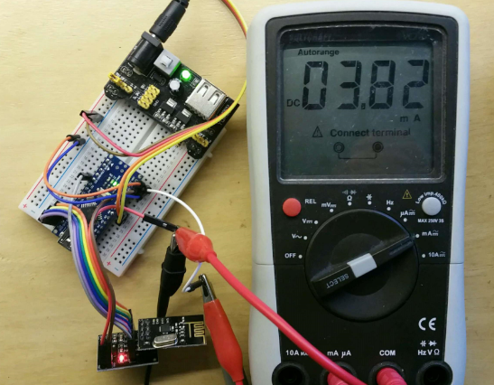
                                          To demonstrate what happens I made some measurements on the NRF24L01+PA+LNA power consumption. The nano in the setup runs a simple sketch which sends one value every 100ms and sleeps in between (RF24_PA_MAX).

                                          First is the setup with a standard nRF24L01+ (working clone ;-) ) The current meter measures the current in the power line of the radio (before the regulator to avoid side effects) and has an internal resistance of 3.4 Ohm. The measured current is a kind of random average sample and shows around 4 mA.

                                          0_1464463953266_upload-0a19ffdd-3807-4724-9fd1-c809b69bff96

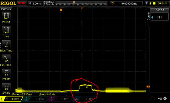
                                          Now look at the waveform of the same current on the scope. I circled the radio send current. The level of pulse is around 70mV which translates to ~20mA (0.07 V/ 3.4 Ohm)
                                          0_1464464509368_upload-399190d7-d122-4ebe-b88b-a2b4352eb726

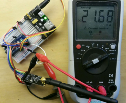
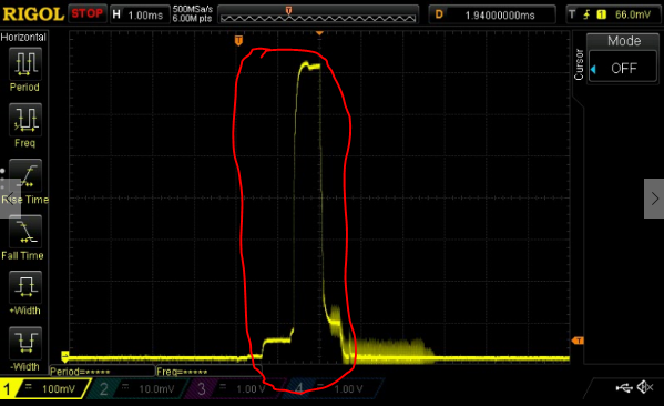
                                          Second is the setup with a the nRF24L01+PA+LNA(working clone ;-) )
                                          0_1464464861402_upload-ea2156f5-3315-47a3-9568-62d1aa6b7687

                                          and the waveform on the scope.. around 700mV translates to ~200mA (0.7V/ 3.4.Ohm) 10 times as much and no comparison to the (random average sample) reading on the current meter of ~22mA (a Fluke meter does not change this ;-))

                                          0_1464465244455_upload-12912f74-4dfb-467a-9ae9-c0990c26eb50

                                          1 Reply Last reply
                                          5
                                          Reply
                                          • Reply as topic
                                          Log in to reply
                                          • Oldest to Newest
                                          • Newest to Oldest
                                          • Most Votes


                                          18

                                          Online

                                          11.7k

                                          Users

                                          11.2k

                                          Topics

                                          113.1k

                                          Posts


                                          Copyright 2025 TBD   |   Forum Guidelines   |   Privacy Policy   |   Terms of Service
                                          • Login

                                          • Don't have an account? Register

                                          • Login or register to search.
                                          • First post
                                            Last post
                                          0
                                          • MySensors
                                          • OpenHardware.io
                                          • Categories
                                          • Recent
                                          • Tags
                                          • Popular