Solar Powered Soil Moisture Sensor
-
It is just a simple pitchfork, like this http://www.aliexpress.com/item/10pcs-Soil-Hygrometer-Detection-Module-Soil-Moisture-Sensor-Probes/2051713873.html
@mfalkvidd
Thanks for posting that link! Even though I don't believe in these types of sensors, I used your link to buy some anyway just because they're so darn cheap! -
@NeverDie
If you just want to know when it is time to water regular home plants (0.5-2 times per week normally) , they are more than good enough.If you want to maximize growth in a farming situation, you'll probably need to go for more advanced measurement methods.
-
Good to know! I'll give it a try--I guess two months from now after they arrive. :wink: My wife has two dozen house plants, and so it would be nice if I could automate the monitoring.
-
I have noisy measurement on analog input for battery voltage.
Anyone that know how I can solve that?
All pictures during night so there shouldn't be any sun that create power. See schematic above how it is connected.
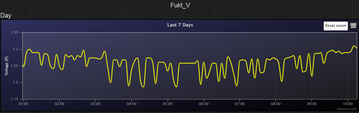
First Node
No cap. Measures every 10 seconds, picture is 5 minute average.
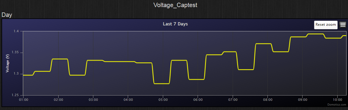
Second Node.
10uF electrolyte cap between GND and A0. Measure every 30 minute. Picture is 5 min average.
Third Node
No cap. Measure every 30 minute. Picture is 5 min average.
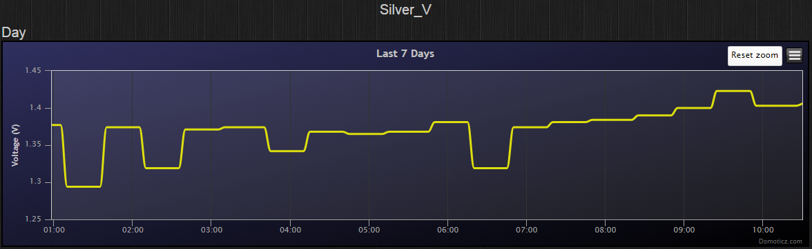
I see a slightly better measurement on Seconds Node but can it be better? This is power directly from the battery and I think the battery should be more stable than this. I have other nodes were I measure the VCC on Arduino and that measurement is extremely stable. Maybe the analog input isn't better than what I get in the pictures?
-
I have noisy measurement on analog input for battery voltage.
Anyone that know how I can solve that?
All pictures during night so there shouldn't be any sun that create power. See schematic above how it is connected.
First Node
No cap. Measures every 10 seconds, picture is 5 minute average.
Second Node.
10uF electrolyte cap between GND and A0. Measure every 30 minute. Picture is 5 min average.
Third Node
No cap. Measure every 30 minute. Picture is 5 min average.
I see a slightly better measurement on Seconds Node but can it be better? This is power directly from the battery and I think the battery should be more stable than this. I have other nodes were I measure the VCC on Arduino and that measurement is extremely stable. Maybe the analog input isn't better than what I get in the pictures?
-
Could you show better scetch how you connect electicaly everything? how you sending data from arduino pro mini to Domoticz?
In your scetch I see only power->battery->step-up->MCU
@Huczas said:
Could you show better scetch how you connect electicaly everything? how you sending data from arduino pro mini to Domoticz?
In your scetch I see only power->battery->step-up->MCU
Electric connection as the attached schematic and NRF you connect according to MySensors instruction.
Data is sent through the NRF with attached sketch -
@flopp I had exactly the same problem with a solar powered node. I solved it by moving the battery measurement around in the sketch. The analog measurement is sensitive..
-
@flopp I had exactly the same problem with a solar powered node. I solved it by moving the battery measurement around in the sketch. The analog measurement is sensitive..
-
-
Updated electric sketch with Connectors. This is useful if the battery gets empty then you need to disconnect Arduino so the battery can get charged.
@flopp Maybe i miss something but I think the connector should be mounted between the battery and the Vin on the step-up. You mounted it on the A0, it´s just the voltage check port.
In the original lamp there was what i think is a charge regulator between the solar cell and the batteri, did you keep that one or you just put the solar cell to the battery ?
Thanks for a nice idé to use this lamp.
-
@flopp Maybe i miss something but I think the connector should be mounted between the battery and the Vin on the step-up. You mounted it on the A0, it´s just the voltage check port.
In the original lamp there was what i think is a charge regulator between the solar cell and the batteri, did you keep that one or you just put the solar cell to the battery ?
Thanks for a nice idé to use this lamp.
@pettib said:
@flopp Maybe i miss something but I think the connector should be mounted between the battery and the Vin on the step-up. You mounted it on the A0, it´s just the voltage check port.
Thanks, I was to quick when adding the connectors
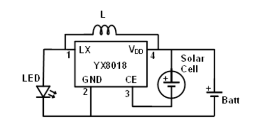
In the original lamp there was what i think is a charge regulator between the solar cell and the batteri, did you keep that one or you just put the solar cell to the battery ?
I removed the small IC, YX8108. Below is a schematic for YX8108
-
@pettib said:
@flopp Maybe i miss something but I think the connector should be mounted between the battery and the Vin on the step-up. You mounted it on the A0, it´s just the voltage check port.
Thanks, I was to quick when adding the connectors
In the original lamp there was what i think is a charge regulator between the solar cell and the batteri, did you keep that one or you just put the solar cell to the battery ?
I removed the small IC, YX8108. Below is a schematic for YX8108
@flopp Is it the led or the solar cell that is working as light sensor ? If i remove the led and measure on the pins there is always power, even if it´s in daylight. So it should be possible to get the power to the step-up Vin from the LED pin, This way we can keep the on/off switch and the (YX8018) Mine is marked HW012.
-
@flopp I found this link. https://ez.analog.com/community/university-program/blog/2014/11/14/hacking-an-led-solar-garden-light
The strange thing is that i can´t get the power on the led pin to go low. But i will remove the IC anyway. I made one light 2 days ago but the battery was empty just the day after and i was not able to get it fully charged again. Maybe some bad connection. I will try a new one today. -
@flopp I found this link. https://ez.analog.com/community/university-program/blog/2014/11/14/hacking-an-led-solar-garden-light
The strange thing is that i can´t get the power on the led pin to go low. But i will remove the IC anyway. I made one light 2 days ago but the battery was empty just the day after and i was not able to get it fully charged again. Maybe some bad connection. I will try a new one today.@pettib
Did you remove the power from battery to Arduino when you tried to charge it again?
I tried to charge r battery for 1-2 days when I had arduino connected, didn't work. After I removed it and out the "lamp" in the sun for 5 hours I could connect the Arduino again and then I was on track again. -
@pettib
Did you remove the power from battery to Arduino when you tried to charge it again?
I tried to charge r battery for 1-2 days when I had arduino connected, didn't work. After I removed it and out the "lamp" in the sun for 5 hours I could connect the Arduino again and then I was on track again. -
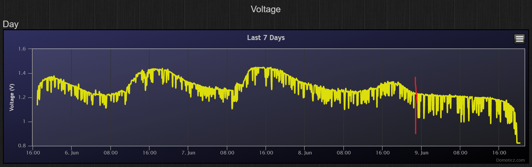
update
I've let it be outdoor in the sun during 2-3 days now and it works well.
yesterday I took one of them and placed it in the garage, totally black whole day not even a lamp.
red line is when I moved it to the garage.
it is sending every 10 second. After ~20 hours the battery was to low to be able to run Pro Mini