Internet of Poultry - Fully automated chicken shed
-
Is it important to know that all the chickens are in the coup before you close the door or are we just assuming they are all inside at a certain time?
-
Is it important to know that all the chickens are in the coup before you close the door or are we just assuming they are all inside at a certain time?
@TommySharp said:
Is it important to know that all the chickens are in the coup before you close the door or are we just assuming they are all inside at a certain time?
I use a light sensor and close the door at <5 lux. They are allways in by then.
-
Is it important to know that all the chickens are in the coup before you close the door or are we just assuming they are all inside at a certain time?
@TommySharp
Maybe all the chickens needs to be wearing a RFID tag, and then clsoe door when all counted RFID tags are inside (RFID reader could maybe be close to water/food supply) -
Is it important to know that all the chickens are in the coup before you close the door or are we just assuming they are all inside at a certain time?
@TommySharp, after some observation I set the light limit to 18 [something], I don't trust the light sensor to output Lux accurately. Till now they've always been inside when the door closes. They're social animal by the way, if one goes indoor at dawn, the other one follows within minutes.
-
@TommySharp, after some observation I set the light limit to 18 [something], I don't trust the light sensor to output Lux accurately. Till now they've always been inside when the door closes. They're social animal by the way, if one goes indoor at dawn, the other one follows within minutes.
-
@Fabien looks to be 1.5m fence around it, which could also keep the foxes out. But again, what do I know :laughing:
-
Yes, we have foxes (and rats) in the neighbourhood. Chicks get eaten if not locked up at night. The fence is only 1m high, but won't keep a fox away from the chickens.
I thought about RfId, but question is if one reader will detect tags anywhere in the shed.
Voice recognition is another option to account for all chickens. Maybe when I find the time. Pool automation must be taken care of first :-)
Anyway, it works as it is. Just need to set the light level in between chicken bed time and fox lunch time. -
Yes, we have foxes (and rats) in the neighbourhood. Chicks get eaten if not locked up at night. The fence is only 1m high, but won't keep a fox away from the chickens.
I thought about RfId, but question is if one reader will detect tags anywhere in the shed.
Voice recognition is another option to account for all chickens. Maybe when I find the time. Pool automation must be taken care of first :-)
Anyway, it works as it is. Just need to set the light level in between chicken bed time and fox lunch time.First off, excellent design. Great job!
I have had one of these running for a while. I did not want mine to react to light levels because I did not want it to close during a thunderstorm, etc. and lock the chickens out. That being said, I have mine close 20 minutes after sunset and open 20 minutes after sunrise. The first couple of nights some of the chickens were locked out because they came home to late. I had to manually let them in. After a couple of days they learned quickly (despite not being very smart creatures) and they head to the house early before the door closes. After that, my camera alerts me to any movement in the house. I have only had one false alarm in a couple of months.
I have a pretty strong outdoor pen and I have still had multiple black snakes, one raccoon, and one possum get in. The raccoon ate a chicken and one snake bit one. After installing the door I have not had one injured chicken.
Mine is pretty low tech. I used a single push button and mysensored a relay board that turns a dc motor with a 3d printed gear that raises/lowers the door. I have had zero problems with it since installed. Thanks Hek!
The one big thing I learned, Transient Voltage Suppressor. I used a larger dc motor due to the weight of my door and every time the door opened it scrambled the Arduino with electric interference. Took me forever to figure out what the problem was and how to fix it.
Now if I can just figure out how to mysensor it to let me know when a chicken lays an egg.....
-
First off, excellent design. Great job!
I have had one of these running for a while. I did not want mine to react to light levels because I did not want it to close during a thunderstorm, etc. and lock the chickens out. That being said, I have mine close 20 minutes after sunset and open 20 minutes after sunrise. The first couple of nights some of the chickens were locked out because they came home to late. I had to manually let them in. After a couple of days they learned quickly (despite not being very smart creatures) and they head to the house early before the door closes. After that, my camera alerts me to any movement in the house. I have only had one false alarm in a couple of months.
I have a pretty strong outdoor pen and I have still had multiple black snakes, one raccoon, and one possum get in. The raccoon ate a chicken and one snake bit one. After installing the door I have not had one injured chicken.
Mine is pretty low tech. I used a single push button and mysensored a relay board that turns a dc motor with a 3d printed gear that raises/lowers the door. I have had zero problems with it since installed. Thanks Hek!
The one big thing I learned, Transient Voltage Suppressor. I used a larger dc motor due to the weight of my door and every time the door opened it scrambled the Arduino with electric interference. Took me forever to figure out what the problem was and how to fix it.
Now if I can just figure out how to mysensor it to let me know when a chicken lays an egg.....
@stefaanv I had to view the pictures again :smiley: it still is a very nice project. And the router was a nice idea for my experiment to remotely upload sketches in the garden instead of picking the whole device up back into the house.. I'll have to look into that a little bit further to figure out how I can use it..
-
@sincze beware, the router solution isn't perfect. Sometimes the connection drop out for no apparent reason. The advantage is that you get full debug info over the serial port. I'm going to have a look at OTA updates for future projects.
-
Hi @stefaanv i'm very new to mysensors but am awaiting some parcels to arrive to try my hand at a few things. First on the list is two water tank level sensors, but next will probably be our chook yard automation system. Love this project! It's inspired me to keep dreaming and designing. It would be really helpful to see a few more things in detail like what battery are you using, solar panel, and the door activation system. Also is there another way to do remote upload of sketches?
-
I've had a similar setup run for over a year. Last week my ln298 broke so the door doesn't open and close anymore. Waiting on spare parts. I have guillotine style door with reed switches on top and bottom.
-
Hi @stefaanv i'm very new to mysensors but am awaiting some parcels to arrive to try my hand at a few things. First on the list is two water tank level sensors, but next will probably be our chook yard automation system. Love this project! It's inspired me to keep dreaming and designing. It would be really helpful to see a few more things in detail like what battery are you using, solar panel, and the door activation system. Also is there another way to do remote upload of sketches?
@breimann , all of that will take a few posts to explain. Bear with me.
The door mechanism took a lot of trial and error. My biggest advise is to estimate the torque needed to open the door before ordering any components.
Due to lack of a dynamometer, here is how I tackled the problem :
Attach an elastic band to the door at some position where you know the distance to the hinges (15cm in my case)
Pulls the elastic band towards you in a right angle to the door until the door starts to move. Measure or estimate how much the elastic band is stretched (in my case, I measured +/-30cm). Be careful the door doesn't smach into your face :-)
Disconnect the elastic band from the door and suspend some adjustable weight to it until it is stretched the same amount as before. I used a small bottle, an iron wire and changed the amount of water in the bottle.
 0_1472748734920_bottle.jpg
Measure the weight
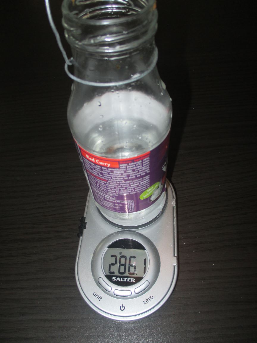 0_1472748775095_bottle on scale.jpg
The torque is distance (to the hinges) x the weight, in my case 15cm x 0.285kg = 4.275 kg.cm
I selected a Modelcraft RB350600-0A101R Transmissiemotor 12 V 1:600 (25€ at Conrad).
According to the datasheet, at 3.44kg.cm (closest in the list), the motor should run at 9,46 rpm and consume 0,14A (12V).
In reality, the motor takes about 3,5s to make half a turn, which amounts to 8,6 rpm and pulls between 150 and 200mA with a startup current of +/- 350mA. Pretty close to what the data sheet says !For the actuation of the motor, I use two relays of a Seeeduino relay shield of which I connected the NO to 0V, the NC to 12V and each motor wire to one of the COM. The resulting behavior is
R1 open, R2 open ==> motor stops
R1 closed, R2 open ==> motor turns CW
R1 open, R2 closed ==> motor turns CCW
R1 closed, R2 closed==> motor stopsSome more advise,
Don't try to open the door with a stepper motor. i tried it and I got bad oscillations.
A servo motor could also work, but you'll have to find one that can deliver the torque. -
Hi @stefaanv i'm very new to mysensors but am awaiting some parcels to arrive to try my hand at a few things. First on the list is two water tank level sensors, but next will probably be our chook yard automation system. Love this project! It's inspired me to keep dreaming and designing. It would be really helpful to see a few more things in detail like what battery are you using, solar panel, and the door activation system. Also is there another way to do remote upload of sketches?
@breimann , door mechanism and end-of-run contacts
I did a few attempt to make the door arm out of wood, but wasn't happy with any of them. The biggest problem was to connect the arm to the motor. I usually use the below cable connectors to fasten something to a shaft, but the shaft of the motor is 6mm diam while the biggest connector I can find can only take a 5mm shaft.
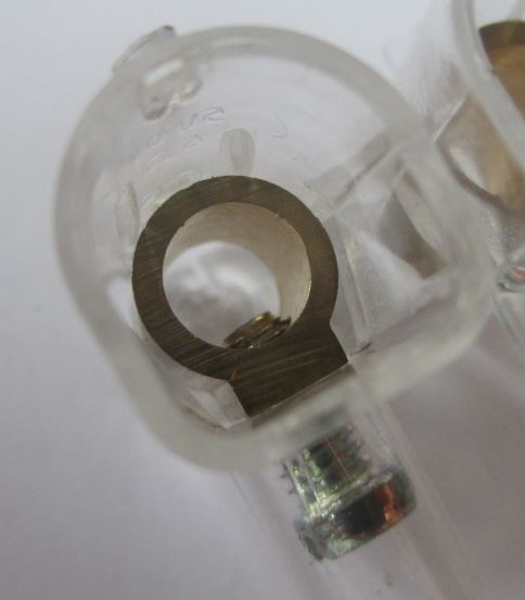
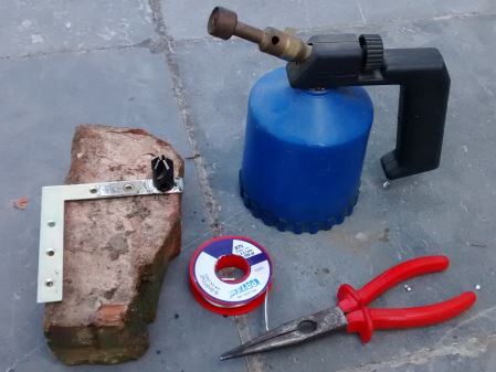
In the end I bought two steel corner pieces in the closest DIY shop and adapted them with a drill and a grinder.
In the same DIY shop I found a cheap router which was fastened to a 6mm drill with a small inbus screw, the router is the black piece in the below photos.
After some attempts to glue to router to the corner piece, I decided to solder them together with plumbing solder. If you attempt this, be carefull not to burn your fingers. I takes a few minutes to cool down.
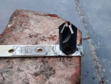
The end result, when mounted in the shed looks like this
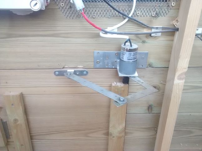
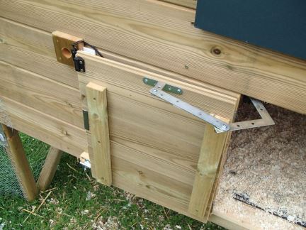
Here is a video of the door in action
0_1472754055923_Video deurtje.mp4In the pictures and the video you can see the end-of-run magnetic switches which I use to detect the open and close position of the door. These are connected to Arduino input pins.
-
Hi @stefaanv i'm very new to mysensors but am awaiting some parcels to arrive to try my hand at a few things. First on the list is two water tank level sensors, but next will probably be our chook yard automation system. Love this project! It's inspired me to keep dreaming and designing. It would be really helpful to see a few more things in detail like what battery are you using, solar panel, and the door activation system. Also is there another way to do remote upload of sketches?
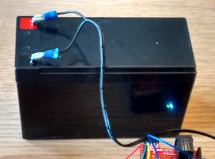
@breimann , Battery and solar panels
I'm using a Seeeduino instead of an Arduino because it is more flexible. The (measured) power consumption is about 45mA @ 12V. Since I wanted to bridge a 10day holiday period securely (assuming no input from the solar panels), I selected a 10Ah (240h x 45mA = 10800mAh) Sealed Lead Acid battery from dynoeurope.
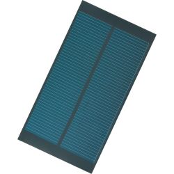
For the solar panels, I chose two 1.35 Wp 9V 150mA panels. 2x9V=18V >14.1V which is typically used to charge a 12V lead acid battery.
At first, I just connected the 2 panels in series across the battery and the arduino. This turned out to be a really bad idea ! The system stopped working when the battery was depleted to 4.5V. This wrecked the battery so I had to buy a new one.
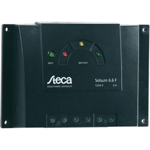
Together with the new battery, I bought a Steca Solsum 6.6 F Solar charger (12V 6A) which provides over- and undervoltage protection. It also provides a suitable charging voltage for lead acid batteries.
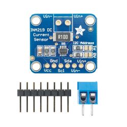
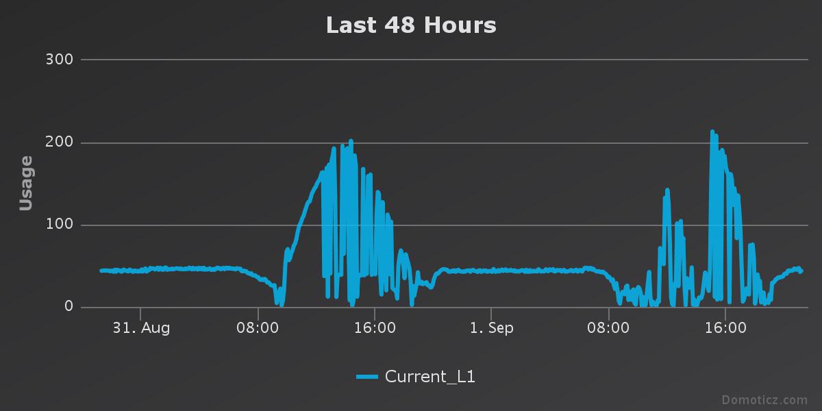
To be able to track the battery level, I attached an INA219 DC current sensor directly to the battery (it is supposed to be connected to the solar panel). It connects to the Seeeduino over i²c and measures current and voltage of the battery.
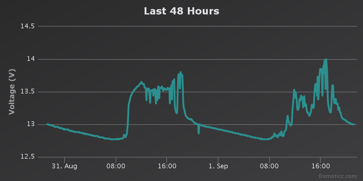
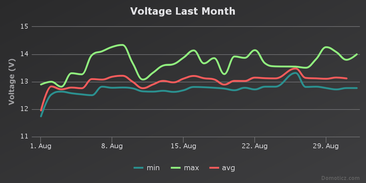
This allows me to get nice graphs of the energy production and consumption in the system. Beware that due to an error in Domoticz, negative currents are shown as positive in the charts.Voltage charts
Current chart
After some time, I decided to double the amount of solar panels.
When I connected the four panels in series I saw no difference at all in the charts.
When however, I connected the 4 panels 2 in series and 2 groups in parallel I found the produced current was doubled. After some investigation I understand that the Steca charger simple cuts the excess voltage of the panels to protect the battery but doesn't convert the energy in an efficient way. What I really need is an MPPT (Maximum Power Point Tracking) charger.
These however cost a small fortune, so in the name of matrimonial peace keeping, I decided to leave it like it is :-) -
@breimann , door mechanism and end-of-run contacts
I did a few attempt to make the door arm out of wood, but wasn't happy with any of them. The biggest problem was to connect the arm to the motor. I usually use the below cable connectors to fasten something to a shaft, but the shaft of the motor is 6mm diam while the biggest connector I can find can only take a 5mm shaft.
In the end I bought two steel corner pieces in the closest DIY shop and adapted them with a drill and a grinder.
In the same DIY shop I found a cheap router which was fastened to a 6mm drill with a small inbus screw, the router is the black piece in the below photos.
After some attempts to glue to router to the corner piece, I decided to solder them together with plumbing solder. If you attempt this, be carefull not to burn your fingers. I takes a few minutes to cool down.
The end result, when mounted in the shed looks like this
Here is a video of the door in action
0_1472754055923_Video deurtje.mp4In the pictures and the video you can see the end-of-run magnetic switches which I use to detect the open and close position of the door. These are connected to Arduino input pins.
@stefaanv
Door mechanism and end of run contacts
This is great info!
A couple questions.- Are you just using standard door hinges x 2 on the door on the outside?
- Is that a magnetic latch you have once it closes to stop a chook accidentally (or deliberately?? ;)) pushing against it?
- Did you buy the motor with the tube to fit inside it and bracket or did you fashion that yourself?
Thankyou!