UI5 Mysensors library 2.0 gateway issues
-
nextAvailiableRadioId will be called if an id request comes in (even if inclusion mode is off). The array is not global. It's one array per gatewateway.
I wonder why https://github.com/mysensors/Vera/blob/development/L_Arduino.lua#L299-L307 does not return the first available id in your setup.
@hek said:
I wonder why https://github.com/mysensors/Vera/blob/development/L_Arduino.lua#L299-L307 does not return the first available id in your setup.
My point was that it DOES in fact return ID 1, which is the first available ID. If you look at my notations on the screen shot next to "Plugged battery in here" you will see it. But when the node doesn't accept that ID it makes another ID request, which then the Vera plugin tries to hand out another ID. Since it already tried to hand out ID 1, it moves on to attempting to hand out ID 2. This also gets no response from the node to accept it. If I leave the node plugged in searching for an ID, the plugin will run through all 255 IDs in the availableIds[] array at which point the nextAvailiableRadioId() method will log "No available IDs" because it had gone through all of the IDs and filled the array with false values. This is what brought up this question:
- If a node doesn't respond back that it accepted that node ID, should the plugin mark that ID as unavailable? Clearly that is what is happening. Is there even a way to tell if the node responds back saying that it got the ID?
The way I see it, if the node does an ID request and the plugin tries to hand one out but the node does not respond that it accepted it (for whatever reason), the plugin should notify the user that there was a request that wasn't accepted. And that is why I asked this question:
- It appears that the node is not responding to the node ID response. What should I see in the serial monitor from the debug information in the node debug log to tell if it receives the response and if it responds back?
Knowing the answer to that will help with what I think should be the next logical step, and that is to figure out if the node receives the ID handed to it by the Vera plugin and if so, is the node processing it correctly.
-
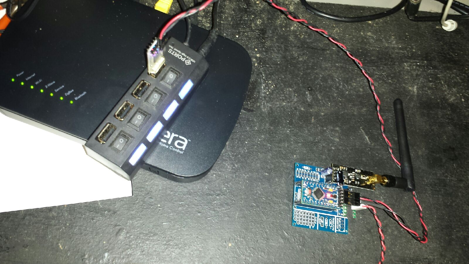
When I first set up the gateway for Domoticz I had a standard nRF24L01+ radio. for that I had a 4.7uf cap mounted on the newbie PCB. I later switched it with a NRF24L01+PA+LNA that I had from another node project and that had a 10uf cap mounted across the power rails right on the radio. This whole setup worked perfectly in Donoticz. Domoticz handed out the IDs fine. The node I am testing was added to my Domoticz setup after switching to the PA+LNA radio. Here is an image of my Vera setup.
If you look at the gateway board, you can see the caps. One is purple and mounted to the PCB next to the radio connector. The other one is black and mounted on top of the radio. Since parallel capacitance adds, that should be about 14.7uf of capacitance at the radio.What should I see in the serial monitor on the node when the gateway responds?
-
I meant what should I see in the serial monitor? This is what is being reported:
TSM:INIT
TSM:RADIO:OK
TSM:FPAR
TSP:MSG:SEND 255-255-255-255 s=255,c=3,t=7,pt=0,l=0,sg=0,ft=0,st=bc:
TSP:MSG:READ 0-0-255 s=255,c=3,t=8,pt=1,l=1,sg=0:0
TSP:MSG:FPAR RES (ID=0, dist=0)
TSP:MSG:PAR OK (ID=0, dist=1)
TSM:FPAR:OK
TSM:ID
TSP:MSG:SEND 255-255-0-0 s=255,c=3,t=3,pt=0,l=0,sg=0,ft=0,st=ok:
TSM:ID
TSP:MSG:SEND 255-255-0-0 s=255,c=3,t=3,pt=0,l=0,sg=0,ft=0,st=ok:
TSM:ID
TSP:MSG:SEND 255-255-0-0 s=255,c=3,t=3,pt=0,l=0,sg=0,ft=0,st=ok:
TSM:ID
TSP:MSG:SEND 255-255-0-0 s=255,c=3,t=3,pt=0,l=0,sg=0,ft=0,st=ok:
!TSM:CHKID:FAIL (ID=255)
!TSM:FAILURE
TSM:PDT
I am guessing I should see something like "TSP:MSG:READ..."
-
@dbemowsk said:
TSP:MSG:READ 0-0-255 s=255,c=3,t=8,pt=1,l=1,sg=0:0
I know there is somewhere that explains this format seen in the serial monitor, but I can't remember where. The serial API message structure page explains the format that you referred to (255;255;3;0;4;<new node id>), but I need to understand what the s, c, pt, l , sg, ft and st all mean, as well as other information seen in the serial monitor.
-
Just a note. The debug page explains s, c, p, pt, l and sg, but it doesn't explain ft and st. I would assume that an st=ok means that the transmission was successful, but unsure on what ft is. maybe that could be added to the troubleshooting page.
EDIT: my appologies, I see it on the transport messages page.
-
I still do not have this working. Here is a list of things I have tried
- having the sensor right next to the gateway
- changed radios on the gateway
- changed capacitor on the gateway from a 4.7uf to a 47uf
- changed radios on the sensor
- cleared eeprom several times and tried pairing
- tried pairing 2 different sensors (both which worked with Domoticz)
- tried both the development and standard UI7 versions of the plugin
One of the things that I have not tried as of yet is changing the USB FTDI adapter. I am pretty sure I have a spare in the parts box. IF not, I will try the one that I use for programming my sensors. I will also test the FTDI I have connected to Vera for programming my sensors to see if it can do that.
-
So it appears that the saga has been solved. The problem in fact WAS with the FTDI adapter. In all of the testing that I did I am guessing that the FTDI's receive data was working, but the transmit data was the issue. I put my spare FTDI on and Vera was detecting devices left and right. I think I am going to have to redo the inclusion because it said that there were 5 devices found, but nothing was added to Vera, but like I say, the devices did not appear to be presenting at the time.
I want to say though that I appreciate all the time that people spent trying to help me get this going. This forum is a GREAT crowd of people.
Hello! It looks like you're interested in this conversation, but you don't have an account yet.
Getting fed up of having to scroll through the same posts each visit? When you register for an account, you'll always come back to exactly where you were before, and choose to be notified of new replies (either via email, or push notification). You'll also be able to save bookmarks and upvote posts to show your appreciation to other community members.
With your input, this post could be even better 💗
Register Login