Adding local sensor to NodeMCU gateway
-
Have been a while and trying to add code to my gateway without succes.
Ive been trying to add a light sensor to my gateway but it isnt recognized by Mynodes controller. In the serial monitor I cannot see anything logging about a sensor.This is what Ive been using so far:
/**
 * The MySensors Arduino library handles the wireless radio link and protocol
 * between your home built sensors/actuators and HA controller of choice.
 * The sensors forms a self healing radio network with optional repeaters. Each
 * repeater and gateway builds a routing tables in EEPROM which keeps track of the
 * network topology allowing messages to be routed to nodes.
 *
 * Created by Henrik Ekblad <henrik.ekblad@mysensors.org>
 * Copyright (C) 2013-2015 Sensnology AB
 * Full contributor list: https://github.com/mysensors/Arduino/graphs/contributors
 *
 * Documentation: http://www.mysensors.org
 * Support Forum: http://forum.mysensors.org
 *
 * This program is free software; you can redistribute it and/or
 * modify it under the terms of the GNU General Public License
 * version 2 as published by the Free Software Foundation.
 *
 *******************************
 *
 * REVISION HISTORY
 * Version 1.0 - Henrik EKblad
 * Contribution by a-lurker and Anticimex,
 * Contribution by Norbert Truchsess <norbert.truchsess@t-online.de>
 * Contribution by Ivo Pullens (ESP8266 support)
 *
 * DESCRIPTION
 * The EthernetGateway sends data received from sensors to the WiFi link.
 * The gateway also accepts input on ethernet interface, which is then sent out to the radio network.
 *
 * VERA CONFIGURATION:
 * Enter "ip-number:port" in the ip-field of the Arduino GW device. This will temporarily override any serial configuration for the Vera plugin.
 * E.g. If you want to use the defualt values in this sketch enter: 192.168.178.66:5003
 *
 * LED purposes:
 * - To use the feature, uncomment any of the MY_DEFAULT_xx_LED_PINs in your sketch, only the LEDs that is defined is used.
 * - RX (green) - blink fast on radio message recieved. In inclusion mode will blink fast only on presentation recieved
 * - TX (yellow) - blink fast on radio message transmitted. In inclusion mode will blink slowly
 * - ERR (red) - fast blink on error during transmission error or recieve crc error
 *
 * See http://www.mysensors.org/build/esp8266_gateway for wiring instructions.
 * nRF24L01+  ESP8266
 * VCC        VCC
 * CE         GPIO4
 * CSN/CS     GPIO15
 * SCK        GPIO14
 * MISO       GPIO12
 * MOSI       GPIO13
 * GND        GND
 *
 * Not all ESP8266 modules have all pins available on their external interface.
 * This code has been tested on an ESP-12 module.
 * The ESP8266 requires a certain pin configuration to download code, and another one to run code:
 * - Connect REST (reset) via 10K pullup resistor to VCC, and via switch to GND ('reset switch')
 * - Connect GPIO15 via 10K pulldown resistor to GND
 * - Connect CH_PD via 10K resistor to VCC
 * - Connect GPIO2 via 10K resistor to VCC
 * - Connect GPIO0 via 10K resistor to VCC, and via switch to GND ('bootload switch')
 *
  * Inclusion mode button:
 * - Connect GPIO5 via switch to GND ('inclusion switch')
 *
 * Hardware SHA204 signing is currently not supported!
 *
 * Make sure to fill in your ssid and WiFi password below for ssid & pass.
 */


// Enable debug prints to serial monitor
#define MY_DEBUG

// Use a bit lower baudrate for serial prints on ESP8266 than default in MyConfig.h
#define MY_BAUD_RATE 9600

// Enables and select radio type (if attached)
#define MY_RADIO_NRF24
//#define MY_RADIO_RFM69

#define MY_GATEWAY_ESP8266

#define MY_ESP8266_SSID "*************"
#define MY_ESP8266_PASSWORD "*******"

// Enable UDP communication
//#define MY_USE_UDP

// Set the hostname for the WiFi Client. This is the hostname
// it will pass to the DHCP server if not static.
// #define MY_ESP8266_HOSTNAME "sensor-gateway"

// Enable MY_IP_ADDRESS here if you want a static ip address (no DHCP)
//#define MY_IP_ADDRESS 192,168,178,87

// If using static ip you need to define Gateway and Subnet address as well
#define MY_IP_GATEWAY_ADDRESS 192,168,178,1
#define MY_IP_SUBNET_ADDRESS 255,255,255,0

// The port to keep open on node server mode
#define MY_PORT 5003

// How many clients should be able to connect to this gateway (default 1)
#define MY_GATEWAY_MAX_CLIENTS 2

// Controller ip address. Enables client mode (default is "server" mode).
// Also enable this if MY_USE_UDP is used and you want sensor data sent somewhere.
#define MY_CONTROLLER_IP_ADDRESS 192,168,0,25

// Enable inclusion mode
#define MY_INCLUSION_MODE_FEATURE

// Enable Inclusion mode button on gateway
// #define MY_INCLUSION_BUTTON_FEATURE
// Set inclusion mode duration (in seconds)
#define MY_INCLUSION_MODE_DURATION 60
// Digital pin used for inclusion mode button
#define MY_INCLUSION_MODE_BUTTON_PIN  3


// Set blinking period
// #define MY_DEFAULT_LED_BLINK_PERIOD 300

// Flash leds on rx/tx/err
// Led pins used if blinking feature is enabled above
#define MY_DEFAULT_ERR_LED_PIN 2  // Error led pin
#define MY_DEFAULT_RX_LED_PIN  2  // Receive led pin
#define MY_DEFAULT_TX_LED_PIN  2  // the PCB, on board LED

#if defined(MY_USE_UDP)
  #include <WiFiUDP.h>
#else
  #include <ESP8266WiFi.h>
#endif
#include <MySensors.h>

#define CHILD_ID_LIGHT 0
#define LIGHT_SENSOR_ANALOG_PIN 0

unsigned long SLEEP_TIME = 30000; // Sleep time between reads (in milliseconds)

MyMessage msg(CHILD_ID_LIGHT, V_LIGHT_LEVEL);
int lastLightLevel;


void presentation()  {
  // Send the sketch version information to the gateway and Controller
  sendSketchInfo("Light Sensor", "1.0");

  // Register all sensors to gateway (they will be created as child devices)
  present(CHILD_ID_LIGHT, S_LIGHT_LEVEL);
}

void loop()
{
  int16_t lightLevel = (1023-analogRead(LIGHT_SENSOR_ANALOG_PIN))/10.23;
  Serial.println(lightLevel);
  if (lightLevel != lastLightLevel) {
      send(msg.set(lightLevel));
      lastLightLevel = lightLevel;
  }
  sleep(SLEEP_TIME);
}
Have been working all night to get this thing up and running.
Any thoughts?
-
@Wodian I've remove your SSID and password from the sketch. You probably didn't want everybody to have those.
-
i'm having the same problem on seriagateway, even with dev. branch . my local sensor dont present on vera 3. Something it's not working as should on local gateway nodes. the not recent examples, just old examples before 2.0 released
i'm a arduino fan .Even sometimes don't undestanding how to use it :P
-
i'm having the same problem on seriagateway, even with dev. branch . my local sensor dont present on vera 3. Something it's not working as should on local gateway nodes. the not recent examples, just old examples before 2.0 released
-
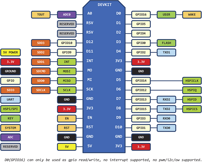
I've been searching for a solution and found one after trial and error. I think my biggest mistake was to use the printed pin numbers instead of the gpio numbers of the nodemcu when adding my temp sensor. My code looks like this, pin 5 is D1:
/**
 * The MySensors Arduino library handles the wireless radio link and protocol
 * between your home built sensors/actuators and HA controller of choice.
 * The sensors forms a self healing radio network with optional repeaters. Each
 * repeater and gateway builds a routing tables in EEPROM which keeps track of the
 * network topology allowing messages to be routed to nodes.
 *
 * Created by Henrik Ekblad <henrik.ekblad@mysensors.org>
 * Copyright (C) 2013-2015 Sensnology AB
 * Full contributor list: https://github.com/mysensors/Arduino/graphs/contributors
 *
 * Documentation: http://www.mysensors.org
 * Support Forum: http://forum.mysensors.org
 *
 * This program is free software; you can redistribute it and/or
 * modify it under the terms of the GNU General Public License
 * version 2 as published by the Free Software Foundation.
 *
 *******************************
 *
 * REVISION HISTORY
 * Version 1.0 - Henrik EKblad
 * Contribution by a-lurker and Anticimex,
 * Contribution by Norbert Truchsess <norbert.truchsess@t-online.de>
 * Contribution by Ivo Pullens (ESP8266 support)
 *
 * DESCRIPTION
 * The EthernetGateway sends data received from sensors to the WiFi link.
 * The gateway also accepts input on ethernet interface, which is then sent out to the radio network.
 *
 * VERA CONFIGURATION:
 * Enter "ip-number:port" in the ip-field of the Arduino GW device. This will temporarily override any serial configuration for the Vera plugin.
 * E.g. If you want to use the defualt values in this sketch enter: 192.168.178.66:5003
 *
 * LED purposes:
 * - To use the feature, uncomment any of the MY_DEFAULT_xx_LED_PINs in your sketch, only the LEDs that is defined is used.
 * - RX (green) - blink fast on radio message recieved. In inclusion mode will blink fast only on presentation recieved
 * - TX (yellow) - blink fast on radio message transmitted. In inclusion mode will blink slowly
 * - ERR (red) - fast blink on error during transmission error or recieve crc error
 *
 * See http://www.mysensors.org/build/esp8266_gateway for wiring instructions.
 * nRF24L01+  ESP8266
 * VCC        VCC
 * CE         GPIO4
 * CSN/CS     GPIO15
 * SCK        GPIO14
 * MISO       GPIO12
 * MOSI       GPIO13
 * GND        GND
 *
 * Not all ESP8266 modules have all pins available on their external interface.
 * This code has been tested on an ESP-12 module.
 * The ESP8266 requires a certain pin configuration to download code, and another one to run code:
 * - Connect REST (reset) via 10K pullup resistor to VCC, and via switch to GND ('reset switch')
 * - Connect GPIO15 via 10K pulldown resistor to GND
 * - Connect CH_PD via 10K resistor to VCC
 * - Connect GPIO2 via 10K resistor to VCC
 * - Connect GPIO0 via 10K resistor to VCC, and via switch to GND ('bootload switch')
 *
  * Inclusion mode button:
 * - Connect GPIO5 via switch to GND ('inclusion switch')
 *
 * Hardware SHA204 signing is currently not supported!
 *
 * Make sure to fill in your ssid and WiFi password below for ssid & pass.
 */


// Enable debug prints to serial monitor
#define MY_DEBUG

// Use a bit lower baudrate for serial prints on ESP8266 than default in MyConfig.h
#define MY_BAUD_RATE 9600

// Enables and select radio type (if attached)
#define MY_RADIO_NRF24
//#define MY_RADIO_RFM69

#define MY_GATEWAY_ESP8266

#define MY_ESP8266_SSID "********"
#define MY_ESP8266_PASSWORD "*********"

// Enable UDP communication
//#define MY_USE_UDP

// Set the hostname for the WiFi Client. This is the hostname
// it will pass to the DHCP server if not static.
// #define MY_ESP8266_HOSTNAME "sensor-gateway"

// Enable MY_IP_ADDRESS here if you want a static ip address (no DHCP)
//#define MY_IP_ADDRESS 192,168,178,87

// If using static ip you need to define Gateway and Subnet address as well
#define MY_IP_GATEWAY_ADDRESS 192,168,178,1
#define MY_IP_SUBNET_ADDRESS 255,255,255,0

// The port to keep open on node server mode
#define MY_PORT 5003

// How many clients should be able to connect to this gateway (default 1)
#define MY_GATEWAY_MAX_CLIENTS 2

// Controller ip address. Enables client mode (default is "server" mode).
// Also enable this if MY_USE_UDP is used and you want sensor data sent somewhere.
//#define MY_CONTROLLER_IP_ADDRESS 192, 168, 178, 68

// Enable inclusion mode
//#define MY_INCLUSION_MODE_FEATURE

// Enable Inclusion mode button on gateway
// #define MY_INCLUSION_BUTTON_FEATURE
// Set inclusion mode duration (in seconds)
#define MY_INCLUSION_MODE_DURATION 60
// Digital pin used for inclusion mode button
#define MY_INCLUSION_MODE_BUTTON_PIN  3


// Set blinking period
// #define MY_DEFAULT_LED_BLINK_PERIOD 300

// Flash leds on rx/tx/err
// Led pins used if blinking feature is enabled above
#define MY_DEFAULT_ERR_LED_PIN 16  // Error led pin
#define MY_DEFAULT_RX_LED_PIN  16  // Receive led pin
#define MY_DEFAULT_TX_LED_PIN  16  // the PCB, on board LED

#if defined(MY_USE_UDP)
#include <WiFiUdp.h>
#endif

#include <ESP8266WiFi.h>

#include <SPI.h>
#include <MySensors.h>
#include <DallasTemperature.h>
#include <OneWire.h>

#define CHILD_ID_TEMP 1

#define COMPARE_TEMP 1 // Send temperature only if changed? 1 = Yes 0 = No

#define ONE_WIRE_BUS 5 // Pin where dallase sensor is connected
#define MAX_ATTACHED_DS18B20 16
unsigned long SLEEP_TIME = 30000; // Sleep time between reads (in milliseconds)
OneWire oneWire(ONE_WIRE_BUS); // Setup a oneWire instance to communicate with any OneWire devices (not just Maxim/Dallas temperature ICs)
DallasTemperature sensors(&oneWire); // Pass the oneWire reference to Dallas Temperature.
float lastTemperature[MAX_ATTACHED_DS18B20];
int numSensors=0;
bool receivedConfig = false;
bool metric = true;
// Initialize temperature message
MyMessage msg(CHILD_ID_TEMP,V_TEMP);

void before()
{
  // Startup up the OneWire library
  sensors.begin();
}


void setup()
{
  // requestTemperatures() will not block current thread
  sensors.setWaitForConversion(false);
}

void presentation()
{
  // Send the sketch version information to the gateway and Controller
  sendSketchInfo("Temperature Sensor", "1.1");

  // Fetch the number of attached temperature sensors
  numSensors = sensors.getDeviceCount();

  // Present all sensors to controller
  for (int i=0; i<numSensors && i<MAX_ATTACHED_DS18B20; i++) {
     present(i, S_TEMP);
  }
}


void loop()
{
  // Fetch temperatures from Dallas sensors
  sensors.requestTemperatures();

  // query conversion time and sleep until conversion completed
  int16_t conversionTime = sensors.millisToWaitForConversion(sensors.getResolution());
  // sleep() call can be replaced by wait() call if node need to process incoming messages (or if node is repeater)
  sleep(conversionTime);

  // Read temperatures and send them to controller
  for (int i=0; i<numSensors && i<MAX_ATTACHED_DS18B20; i++) {

    // Fetch and round temperature to one decimal
    float temperature = static_cast<float>(static_cast<int>((getControllerConfig().isMetric?sensors.getTempCByIndex(i):sensors.getTempFByIndex(i)) * 10.)) / 10.;

    // Only send data if temperature has changed and no error
    #if COMPARE_TEMP == 1
    if (lastTemperature[i] != temperature && temperature != -127.00 && temperature != 85.00) {
    #else
    if (temperature != -127.00 && temperature != 85.00) {
    #endif

      // Send in the new temperature
      send(msg.setSensor(i).set(temperature,1));
      // Save new temperatures for next compare
      lastTemperature[i]=temperature;
    }
  }
  sleep(SLEEP_TIME);
}
I know the thread was old, but I thought a solution would be worth telling :)
Here is a sketch of the pins:
-
o vera lite the problem is : if i add a new sensor and delete it , id stays there..somewere on vera. and next time device will not be find because it is already there. i have to increase node id number on arduino sketch (i don't know if auto id works).
Anyone know why Vera don't really delete devices and kept te ID somewere?i'm a arduino fan .Even sometimes don't undestanding how to use it :P
-
o vera lite the problem is : if i add a new sensor and delete it , id stays there..somewere on vera. and next time device will not be find because it is already there. i have to increase node id number on arduino sketch (i don't know if auto id works).
Anyone know why Vera don't really delete devices and kept te ID somewere? -
@mfalkvidd but then if i have 200 deleted devices .it ill kept everything? how to reset that?
Hello! It looks like you're interested in this conversation, but you don't have an account yet.
Getting fed up of having to scroll through the same posts each visit? When you register for an account, you'll always come back to exactly where you were before, and choose to be notified of new replies (either via email, or push notification). You'll also be able to save bookmarks and upvote posts to show your appreciation to other community members.
With your input, this post could be even better 💗
Register Login