💬 Battery Powered Sensors
-
Consider this option:
Use 2 AA batteries.
Change the BOD on the arduino to something lower than the 2.8V default.
Power everything from the batteries except the sensor.
Use the 5V step-up converter only for the sensor.@ileneken3 Good idea, i think I'll design it that way. I also had a closer look on eBay and found another sensor that runs on 3.3v.
-
"Disconnect or desolder the 3.3 VDC regulator because it is not needed." => Why it isn't needed? I assume it is needed when connecting a sensor that requires 3.3V (e.g. HTU21d or even the RFM69)? I assume the assumption made here is that you're using 2 AA 1.5V batteries? I'm using 3 LR44 (3x1.55V) so I suppose I still need the regulator.
MyController with USB powered WeMos D1/mini ESP8266 MQTT Gateways and battery powered Arduino Pro Mini using the RFM69 radio
-
"Disconnect or desolder the 3.3 VDC regulator because it is not needed." => Why it isn't needed? I assume it is needed when connecting a sensor that requires 3.3V (e.g. HTU21d or even the RFM69)? I assume the assumption made here is that you're using 2 AA 1.5V batteries? I'm using 3 LR44 (3x1.55V) so I suppose I still need the regulator.
-
Hi, i've got a barebones arduino circuit set up with a dht22 sensor. It's powered off 2 aa batteries. All works well with the two batteries even when they are running at about 3.0 volts combined (it would probably run at lower voltages but batteries haven't gone down that far yet). If i power directly from usb with my ftdi interface all works. However, when i add the 3.3v step up, the radio doesn't get a response from the nrf gateway anymore. I have a 4.7u capacitor on the nrf. The gateway is receiving some data but not all as i can see "mygateway1-out/0/255/0/0/18 2.1.1" in my mqtt broker every couple of seconds but the mysensors client never seems to get fully initialised. I've tried two or three of the step ups and checked the voltage with a multimeter and i'm getting circa 3.3v. One thing i did notice is that when i swapped in one of my 3 dht22's it worked initially but then stopped, the other two wouldn't (all work without the step up). I think this is a bit of a red herring but putting in here for information. Any thoughts?
-
share your schematic. from what you are describing it seems like the step up converter is not able to provide enough current.
-
but the dht22 would not work, it requires at least 3.3v (however i succesuffly used it with 3V). I think that NRF has some decoupling capacitors onboard, so unless the boost converter design is not totaly wrong it shouldn't be a problem. schematic would be helpful.
-
but the dht22 would not work, it requires at least 3.3v (however i succesuffly used it with 3V). I think that NRF has some decoupling capacitors onboard, so unless the boost converter design is not totaly wrong it shouldn't be a problem. schematic would be helpful.
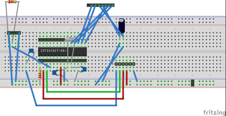
Here is my breadboard design, i'm afraid the schematic in fritzing isn't really in a state to post here. It's unreadable. The resistors shown in the diagram wouldn't have the correct values i used. The values i used are from the arduino site for creating an arduino. The ones shown are used for the sake of creating a pcb. The DHT22 goes on the 4 pin header, the NRF goes on the 8 pin header.
-
@FatBeard said in 💬 Battery Powered Sensors:
goes on
ok, but what about boost converter ? as i understand the problem is when You use the boost converter ? is it some kind of module ? or your design ?
-
@FatBeard said in 💬 Battery Powered Sensors:
goes on
ok, but what about boost converter ? as i understand the problem is when You use the boost converter ? is it some kind of module ? or your design ?
@rozpruwacz Ya, it's a module and it's the 3.3v step up module recommended on this page. Thanks for your help by the way
-
-
@rozpruwacz This one here on aliexpress.
-
unless the dht22 pull up resistor is not to low, which would cause large current when the data pin is held low, i don;t see any mistakes ... are you able to measure the current drawn from the boost converter ?
-
unless the dht22 pull up resistor is not to low, which would cause large current when the data pin is held low, i don;t see any mistakes ... are you able to measure the current drawn from the boost converter ?
@rozpruwacz Both resistors are 10k. I can measure the amps, i'll do this tonight and get back to you. thanks again
-
one other thought, what type of nrf module You use in your gateway ? from my expirience i know that the PA+LNA modules are very sensitive to noise. Do you have other sensors in your network that are affected ? maybe it is the problem with the gateway nrf module and not the sensors nfr module ? You can try to shield the modules somehow.
-
Try adding a 0,1uF cheramic capacitor on the booster from Out to Gnd. Also external capacitor on the radio is crusial!
-
I made progress. So the capacitor idea doesn't seem to work. However rozpruwacz suggested measuring the current which I did. I disconnected the negative wire and put my multimeter in between the negative from the battery and the ground pin on the step up module. I measured 72ma when the device powers up, then it runs at .16ma when in sleep mode. But here is the thing, in this configuration, mysensors worked as a thermometer. I got humidity and temperature readings from the sensor to my mqtt server through the gateway over the nrfs. When I removed the multimeter again from the equation it stopped working. Surely this would hint at what the problem is for someone more familiar with electronics than myself?