Skip to content
  • MySensors
  • OpenHardware.io
  • Categories
  • Recent
  • Tags
  • Popular
Skins
  • Light
  • Brite
  • Cerulean
  • Cosmo
  • Flatly
  • Journal
  • Litera
  • Lumen
  • Lux
  • Materia
  • Minty
  • Morph
  • Pulse
  • Sandstone
  • Simplex
  • Sketchy
  • Spacelab
  • United
  • Yeti
  • Zephyr
  • Dark
  • Cyborg
  • Darkly
  • Quartz
  • Slate
  • Solar
  • Superhero
  • Vapor

  • Default (No Skin)
  • No Skin
Collapse
Brand Logo
  1. Home
  2. Announcements
  3. 💬 Battery Powered Sensors

💬 Battery Powered Sensors

Scheduled Pinned Locked Moved Announcements
battery
347 Posts 55 Posters 67.1k Views 53 Watching
  • Oldest to Newest
  • Newest to Oldest
  • Most Votes
Reply
  • Reply as topic
Log in to reply
This topic has been deleted. Only users with topic management privileges can see it.
  • F Offline
    F Offline
    FatBeard
    wrote on last edited by
    #111

    I made progress. So the capacitor idea doesn't seem to work. However rozpruwacz suggested measuring the current which I did. I disconnected the negative wire and put my multimeter in between the negative from the battery and the ground pin on the step up module. I measured 72ma when the device powers up, then it runs at .16ma when in sleep mode. But here is the thing, in this configuration, mysensors worked as a thermometer. I got humidity and temperature readings from the sensor to my mqtt server through the gateway over the nrfs. When I removed the multimeter again from the equation it stopped working. Surely this would hint at what the problem is for someone more familiar with electronics than myself?

    sundberg84S 1 Reply Last reply
    0
    • F Offline
      F Offline
      FatBeard
      wrote on last edited by
      #112

      Any thoughts on what I could do to fix the issue permanently without the multimeter?

      1 Reply Last reply
      0
      • gohanG Offline
        gohanG Offline
        gohan
        Mod
        wrote on last edited by
        #113

        why don't you connect the radio directly to battery?

        1 Reply Last reply
        0
        • rozpruwaczR Offline
          rozpruwaczR Offline
          rozpruwacz
          wrote on last edited by
          #114

          this is very wierd ... maybe try another nrf module ? also try what gohan suggested. But it should work as it is. I have similar configuration, but the boost converter has pass trough mode, so i can switch it on and off from the atmega and have no problems with that setup, no matter if the boost converter is os or off, the communication is ok. Can you upload a picture of your setup ? maybe we see something you didn't realize is important to say.

          1 Reply Last reply
          0
          • F FatBeard

            I made progress. So the capacitor idea doesn't seem to work. However rozpruwacz suggested measuring the current which I did. I disconnected the negative wire and put my multimeter in between the negative from the battery and the ground pin on the step up module. I measured 72ma when the device powers up, then it runs at .16ma when in sleep mode. But here is the thing, in this configuration, mysensors worked as a thermometer. I got humidity and temperature readings from the sensor to my mqtt server through the gateway over the nrfs. When I removed the multimeter again from the equation it stopped working. Surely this would hint at what the problem is for someone more familiar with electronics than myself?

            sundberg84S Offline
            sundberg84S Offline
            sundberg84
            Hardware Contributor
            wrote on last edited by
            #115

            @FatBeard - Could it be that the step up booster are making alot of noice. When you connect your multimeter it works in some way like a filter and reduces the noice?

            I have made alot of these sensors and i strongly suggest you connect i like @gohan suggest - radio directly to the bat.

            This is how i have created my EasyPCB and with alot of trial and error - radio + booster isnt a good idea.

            https://www.openhardware.io/view/4/EasyNewbie-PCB-for-MySensors

            Controller: Proxmox VM - Home Assistant
            MySensors GW: Arduino Uno - W5100 Ethernet, Gw Shield Nrf24l01+ 2,4Ghz
            MySensors GW: Arduino Uno - Gw Shield RFM69, 433mhz
            RFLink GW - Arduino Mega + RFLink Shield, 433mhz

            F 1 Reply Last reply
            0
            • sundberg84S sundberg84

              @FatBeard - Could it be that the step up booster are making alot of noice. When you connect your multimeter it works in some way like a filter and reduces the noice?

              I have made alot of these sensors and i strongly suggest you connect i like @gohan suggest - radio directly to the bat.

              This is how i have created my EasyPCB and with alot of trial and error - radio + booster isnt a good idea.

              https://www.openhardware.io/view/4/EasyNewbie-PCB-for-MySensors

              F Offline
              F Offline
              FatBeard
              wrote on last edited by
              #116

              @sundberg84 Ok, thanks guys. I'll try your suggestions out tonight. I would have preferred to do it through the step up to get the most out of the batteries but maybe this is not practical.

              rozpruwaczR 1 Reply Last reply
              0
              • gohanG Offline
                gohanG Offline
                gohan
                Mod
                wrote on last edited by
                #117

                maybe you could use the booster, but you would need to analyze the kind of noise and build a specific filter for that.

                1 Reply Last reply
                0
                • F FatBeard

                  @sundberg84 Ok, thanks guys. I'll try your suggestions out tonight. I would have preferred to do it through the step up to get the most out of the batteries but maybe this is not practical.

                  rozpruwaczR Offline
                  rozpruwaczR Offline
                  rozpruwacz
                  wrote on last edited by
                  #118

                  @FatBeard boost converter has limited efficiency, this means that it eat the battery power. Nrf can work down to 1.9 V so it is not so obvious that the booster actually will make your sensor live longer.

                  1 Reply Last reply
                  0
                  • gohanG Offline
                    gohanG Offline
                    gohan
                    Mod
                    wrote on last edited by gohan
                    #119

                    It can help drainig the battery to even lower voltages, but the tradeoff is lower efficiency and noise

                    1 Reply Last reply
                    0
                    • sundberg84S Offline
                      sundberg84S Offline
                      sundberg84
                      Hardware Contributor
                      wrote on last edited by
                      #120

                      Search the forum. Booster VS not booster - its always a tradeoff.
                      Some people go further and skip booster and lower BOD on the arduino instead.
                      I would say 1.9V is pretty good... I have had my longest temp sensor now since the beginning (Almost 3 years) and changed 2xAA once. If you are using sleep and measure once you will get away with a long lasting sensor.

                      Controller: Proxmox VM - Home Assistant
                      MySensors GW: Arduino Uno - W5100 Ethernet, Gw Shield Nrf24l01+ 2,4Ghz
                      MySensors GW: Arduino Uno - Gw Shield RFM69, 433mhz
                      RFLink GW - Arduino Mega + RFLink Shield, 433mhz

                      1 Reply Last reply
                      0
                      • mfalkviddM Offline
                        mfalkviddM Offline
                        mfalkvidd
                        Mod
                        wrote on last edited by mfalkvidd
                        #121

                        At 0.95V per cell, an alkaline battery has delivered about 99% of its total capacity. Look at a discharge curve like this:
                        0_1498143146830_IMG_1741.PNG

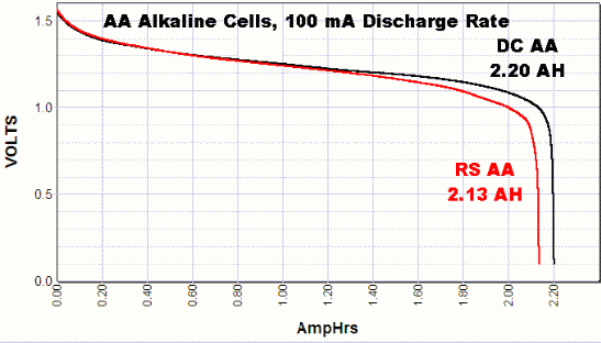
                        So if the booster has more than 1% overhead, using a booster to power nrf24 and atmega328 will give worse battery performance than running directly off 2 alkaline batteries.

                        1 Reply Last reply
                        1
                        • F Offline
                          F Offline
                          FatBeard
                          wrote on last edited by
                          #122

                          Thats for the response guys. So tried connecting directly to the battery. I cut the trace on the pcb, then soldered a wire directly from the vIn to the positive leg of the 4.7u cap that leads to the radio. No joy though. Still same problem.

                          To the point about disabling bod, i have done that already, my issue with that setup though is that my dht22 seems to give inconsistent measurements when operating. It would give readings a degree apart every 5 minutes when the temperature would have remained a lot more stable. I assumed this to be due to the 2x batteries running at just a tad below 3v, while the dht22 is rated at 3.3v. Hence i thought the stepup would fix this problem.

                          sundberg84S 1 Reply Last reply
                          0
                          • gohanG Offline
                            gohanG Offline
                            gohan
                            Mod
                            wrote on last edited by
                            #123

                            Get a more serious sensor like sht31 or si7021 😉

                            1 Reply Last reply
                            1
                            • F FatBeard

                              Thats for the response guys. So tried connecting directly to the battery. I cut the trace on the pcb, then soldered a wire directly from the vIn to the positive leg of the 4.7u cap that leads to the radio. No joy though. Still same problem.

                              To the point about disabling bod, i have done that already, my issue with that setup though is that my dht22 seems to give inconsistent measurements when operating. It would give readings a degree apart every 5 minutes when the temperature would have remained a lot more stable. I assumed this to be due to the 2x batteries running at just a tad below 3v, while the dht22 is rated at 3.3v. Hence i thought the stepup would fix this problem.

                              sundberg84S Offline
                              sundberg84S Offline
                              sundberg84
                              Hardware Contributor
                              wrote on last edited by sundberg84
                              #124

                              @FatBeard - I use this setup, run the radio from the battery and arduino and dht22 from booster without problems. It should work. About the readings... as gohan said... the dht22 is known for... not that good quality

                              Controller: Proxmox VM - Home Assistant
                              MySensors GW: Arduino Uno - W5100 Ethernet, Gw Shield Nrf24l01+ 2,4Ghz
                              MySensors GW: Arduino Uno - Gw Shield RFM69, 433mhz
                              RFLink GW - Arduino Mega + RFLink Shield, 433mhz

                              F 2 Replies Last reply
                              0
                              • sundberg84S sundberg84

                                @FatBeard - I use this setup, run the radio from the battery and arduino and dht22 from booster without problems. It should work. About the readings... as gohan said... the dht22 is known for... not that good quality

                                F Offline
                                F Offline
                                FatBeard
                                wrote on last edited by
                                #125

                                I've actually ordered some bme280s which I'm waiting on, I think they will work down to low voltages too. So hopefully that will sort this issue by not needing the step up.

                                I would like to still to be able to figure out this problem though. I tried removing the dht22 completely to see if it was contributing to the problem, no luck. I've tried various capacitors over the ground and vout to no avail.

                                How would I go about analysing noise on the circuit?

                                1 Reply Last reply
                                0
                                • sundberg84S sundberg84

                                  @FatBeard - I use this setup, run the radio from the battery and arduino and dht22 from booster without problems. It should work. About the readings... as gohan said... the dht22 is known for... not that good quality

                                  F Offline
                                  F Offline
                                  FatBeard
                                  wrote on last edited by
                                  #126

                                  @sundberg84 I'll also take a look at your pcb. I was trying to achieve a pcb like that. A generic one to use with various sensors. I Was hoping to do it myself for the sake of learning. But I may have change tact.

                                  sundberg84S 1 Reply Last reply
                                  1
                                  • F FatBeard

                                    @sundberg84 I'll also take a look at your pcb. I was trying to achieve a pcb like that. A generic one to use with various sensors. I Was hoping to do it myself for the sake of learning. But I may have change tact.

                                    sundberg84S Offline
                                    sundberg84S Offline
                                    sundberg84
                                    Hardware Contributor
                                    wrote on last edited by sundberg84
                                    #127

                                    @FatBeard - I would start by changing the Nrf24l01+ - there are some really bad ones out there.
                                    Second I would rewire everyhing from/to the radio. After that I would rewire everything else and maybe change the arduino. As you said, removing all sensors and try debug in "bare minimun" (Power, Arudino and Radio) is a good idea. You can create a fake motion sensor sketch for example sending 1/0 with a 10 sec delay in between just to test the setup (without sensor attached).

                                    Controller: Proxmox VM - Home Assistant
                                    MySensors GW: Arduino Uno - W5100 Ethernet, Gw Shield Nrf24l01+ 2,4Ghz
                                    MySensors GW: Arduino Uno - Gw Shield RFM69, 433mhz
                                    RFLink GW - Arduino Mega + RFLink Shield, 433mhz

                                    F 1 Reply Last reply
                                    0
                                    • S Offline
                                      S Offline
                                      sineverba
                                      Hardware Contributor
                                      wrote on last edited by sineverba
                                      #128

                                      I'm using an approach read some thread bottom. Direct 2XAA to the Atmega barebone @8Mhz with BOD disabled and step up (not very efficient) to port the voltage of the batteries to a 3.3v for the DHT22. I'm reading the voltage with "secret voltmeter" example posted (https://provideyourown.com/2012/secret-arduino-voltmeter-measure-battery-voltage/ )

                                      The Atmega sleep for 10 minutes, take reading and if different sends to the gateway (as your sketches). I want shutdown the booster, as it is not very efficient. I did have a debate on arduino forum: https://forum.arduino.cc/index.php?topic=488315.0

                                      Basically, a part that I don't absolutely "cut the ground" with a NPN, otherwise I could have issues with different potential grounds etc etc, I don't know anymore if my design is secure and can works.

                                      For all friday, saturday and sunday my node was power on without issues, but I don't want my house burning for a short circuit from batteries...

                                      This is base fritzing draw:

                                      alt text

                                      And this is the real pictures of node:

                                      alt text

                                      And final this is the not-so-efficient booster: https://www.amazon.it/gp/product/B06XHJCHX6/ref=oh_aui_detailpage_o00_s00?ie=UTF8&psc=1 and regulated exit to 3.3v.

                                      (Voltage goes down from friday to today from 2.74 to 2.63).

                                      Am I wrong with my connections? Thank you to all....

                                      zboblamontZ 1 Reply Last reply
                                      0
                                      • S sineverba

                                        I'm using an approach read some thread bottom. Direct 2XAA to the Atmega barebone @8Mhz with BOD disabled and step up (not very efficient) to port the voltage of the batteries to a 3.3v for the DHT22. I'm reading the voltage with "secret voltmeter" example posted (https://provideyourown.com/2012/secret-arduino-voltmeter-measure-battery-voltage/ )

                                        The Atmega sleep for 10 minutes, take reading and if different sends to the gateway (as your sketches). I want shutdown the booster, as it is not very efficient. I did have a debate on arduino forum: https://forum.arduino.cc/index.php?topic=488315.0

                                        Basically, a part that I don't absolutely "cut the ground" with a NPN, otherwise I could have issues with different potential grounds etc etc, I don't know anymore if my design is secure and can works.

                                        For all friday, saturday and sunday my node was power on without issues, but I don't want my house burning for a short circuit from batteries...

                                        This is base fritzing draw:

                                        alt text

                                        And this is the real pictures of node:

                                        alt text

                                        And final this is the not-so-efficient booster: https://www.amazon.it/gp/product/B06XHJCHX6/ref=oh_aui_detailpage_o00_s00?ie=UTF8&psc=1 and regulated exit to 3.3v.

                                        (Voltage goes down from friday to today from 2.74 to 2.63).

                                        Am I wrong with my connections? Thank you to all....

                                        zboblamontZ Offline
                                        zboblamontZ Offline
                                        zboblamont
                                        wrote on last edited by
                                        #129

                                        @sineverba I gave up trying to cross connect power controls directly and went for bistable telecoms relays, 100mW fire 30ms max latched stay open until you reverse signals from + & - pins. Works a treat, powered only for duration of latch....pity the sensor it controlled was shit, but hey ho....small steps

                                        S 1 Reply Last reply
                                        0
                                        • zboblamontZ zboblamont

                                          @sineverba I gave up trying to cross connect power controls directly and went for bistable telecoms relays, 100mW fire 30ms max latched stay open until you reverse signals from + & - pins. Works a treat, powered only for duration of latch....pity the sensor it controlled was shit, but hey ho....small steps

                                          S Offline
                                          S Offline
                                          sineverba
                                          Hardware Contributor
                                          wrote on last edited by
                                          #130

                                          @zboblamont

                                          A bistable could cost more than entire node :D

                                          But it could be an idea... instead of NPN. But remain my doubt.... for the moment, with node powered in this mode..... Am I in danger of burn battery / node / house? :(

                                          zboblamontZ 1 Reply Last reply
                                          0
                                          Reply
                                          • Reply as topic
                                          Log in to reply
                                          • Oldest to Newest
                                          • Newest to Oldest
                                          • Most Votes


                                          20

                                          Online

                                          11.7k

                                          Users

                                          11.2k

                                          Topics

                                          113.0k

                                          Posts


                                          Copyright 2019 TBD   |   Forum Guidelines   |   Privacy Policy   |   Terms of Service
                                          • Login

                                          • Don't have an account? Register

                                          • Login or register to search.
                                          • First post
                                            Last post
                                          0
                                          • MySensors
                                          • OpenHardware.io
                                          • Categories
                                          • Recent
                                          • Tags
                                          • Popular