💬 Battery Powered Sensors
-
unless the dht22 pull up resistor is not to low, which would cause large current when the data pin is held low, i don;t see any mistakes ... are you able to measure the current drawn from the boost converter ?
@rozpruwacz Both resistors are 10k. I can measure the amps, i'll do this tonight and get back to you. thanks again
-
one other thought, what type of nrf module You use in your gateway ? from my expirience i know that the PA+LNA modules are very sensitive to noise. Do you have other sensors in your network that are affected ? maybe it is the problem with the gateway nrf module and not the sensors nfr module ? You can try to shield the modules somehow.
-
Try adding a 0,1uF cheramic capacitor on the booster from Out to Gnd. Also external capacitor on the radio is crusial!
-
I made progress. So the capacitor idea doesn't seem to work. However rozpruwacz suggested measuring the current which I did. I disconnected the negative wire and put my multimeter in between the negative from the battery and the ground pin on the step up module. I measured 72ma when the device powers up, then it runs at .16ma when in sleep mode. But here is the thing, in this configuration, mysensors worked as a thermometer. I got humidity and temperature readings from the sensor to my mqtt server through the gateway over the nrfs. When I removed the multimeter again from the equation it stopped working. Surely this would hint at what the problem is for someone more familiar with electronics than myself?
-
this is very wierd ... maybe try another nrf module ? also try what gohan suggested. But it should work as it is. I have similar configuration, but the boost converter has pass trough mode, so i can switch it on and off from the atmega and have no problems with that setup, no matter if the boost converter is os or off, the communication is ok. Can you upload a picture of your setup ? maybe we see something you didn't realize is important to say.
-
I made progress. So the capacitor idea doesn't seem to work. However rozpruwacz suggested measuring the current which I did. I disconnected the negative wire and put my multimeter in between the negative from the battery and the ground pin on the step up module. I measured 72ma when the device powers up, then it runs at .16ma when in sleep mode. But here is the thing, in this configuration, mysensors worked as a thermometer. I got humidity and temperature readings from the sensor to my mqtt server through the gateway over the nrfs. When I removed the multimeter again from the equation it stopped working. Surely this would hint at what the problem is for someone more familiar with electronics than myself?
@FatBeard - Could it be that the step up booster are making alot of noice. When you connect your multimeter it works in some way like a filter and reduces the noice?
I have made alot of these sensors and i strongly suggest you connect i like @gohan suggest - radio directly to the bat.
This is how i have created my EasyPCB and with alot of trial and error - radio + booster isnt a good idea.
https://www.openhardware.io/view/4/EasyNewbie-PCB-for-MySensors
-
@sundberg84 Ok, thanks guys. I'll try your suggestions out tonight. I would have preferred to do it through the step up to get the most out of the batteries but maybe this is not practical.
@FatBeard boost converter has limited efficiency, this means that it eat the battery power. Nrf can work down to 1.9 V so it is not so obvious that the booster actually will make your sensor live longer.
-
Search the forum. Booster VS not booster - its always a tradeoff.
Some people go further and skip booster and lower BOD on the arduino instead.
I would say 1.9V is pretty good... I have had my longest temp sensor now since the beginning (Almost 3 years) and changed 2xAA once. If you are using sleep and measure once you will get away with a long lasting sensor. -
At 0.95V per cell, an alkaline battery has delivered about 99% of its total capacity. Look at a discharge curve like this:
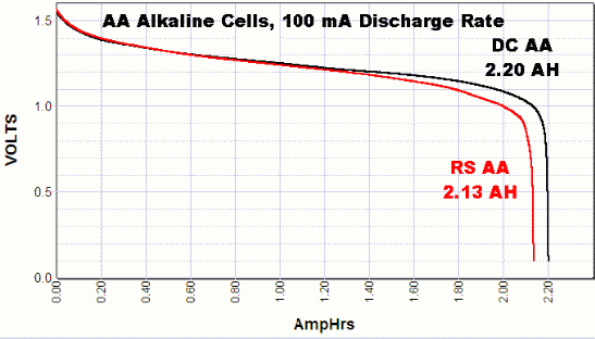
So if the booster has more than 1% overhead, using a booster to power nrf24 and atmega328 will give worse battery performance than running directly off 2 alkaline batteries.
-
Thats for the response guys. So tried connecting directly to the battery. I cut the trace on the pcb, then soldered a wire directly from the vIn to the positive leg of the 4.7u cap that leads to the radio. No joy though. Still same problem.
To the point about disabling bod, i have done that already, my issue with that setup though is that my dht22 seems to give inconsistent measurements when operating. It would give readings a degree apart every 5 minutes when the temperature would have remained a lot more stable. I assumed this to be due to the 2x batteries running at just a tad below 3v, while the dht22 is rated at 3.3v. Hence i thought the stepup would fix this problem.
@FatBeard - I use this setup, run the radio from the battery and arduino and dht22 from booster without problems. It should work. About the readings... as gohan said... the dht22 is known for... not that good quality
-
@FatBeard - I use this setup, run the radio from the battery and arduino and dht22 from booster without problems. It should work. About the readings... as gohan said... the dht22 is known for... not that good quality
I've actually ordered some bme280s which I'm waiting on, I think they will work down to low voltages too. So hopefully that will sort this issue by not needing the step up.
I would like to still to be able to figure out this problem though. I tried removing the dht22 completely to see if it was contributing to the problem, no luck. I've tried various capacitors over the ground and vout to no avail.
How would I go about analysing noise on the circuit?
-
@FatBeard - I use this setup, run the radio from the battery and arduino and dht22 from booster without problems. It should work. About the readings... as gohan said... the dht22 is known for... not that good quality
@sundberg84 I'll also take a look at your pcb. I was trying to achieve a pcb like that. A generic one to use with various sensors. I Was hoping to do it myself for the sake of learning. But I may have change tact.
Hello! It looks like you're interested in this conversation, but you don't have an account yet.
Getting fed up of having to scroll through the same posts each visit? When you register for an account, you'll always come back to exactly where you were before, and choose to be notified of new replies (either via email, or push notification). You'll also be able to save bookmarks and upvote posts to show your appreciation to other community members.
With your input, this post could be even better 💗
Register Login