💬 Battery Powered Sensors
-
@evb yes I see your point. But changing things without understanding the background is troublesome, in my experience. Whoever created the original image probably had a good reason to write the N/C part. Therefore, I would prefer if any of the "Ancients" (i.e. people who joined the project before me) could chip in.
@mfalkvidd Don't know if I'm qualified, but I've vague memory (or a wild guess). I think there were some pro-mini models that lost connection to one vcc-pin if you made the cut after the voltage regulator. And btw I never really know why the cutting method was so popular.
-
@mfalkvidd Don't know if I'm qualified, but I've vague memory (or a wild guess). I think there were some pro-mini models that lost connection to one vcc-pin if you made the cut after the voltage regulator. And btw I never really know why the cutting method was so popular.
@m26872, your memory is correct. There are or were pro-mini models who lost connection on the VCC pin at the right if you removed the power regulator. (https://forum.pimatic.org/topic/383/tips-battery-powered-sensors/2).
My batch of chinese pro mini's are not loosing their connection with the VCC pin at the right.
@mfalkvidd, you can maybe adapt the wiki article with this extra info?
-
Meanwhile I found following forum topic : https://forum.mysensors.org/topic/2067/my-slim-2aa-battery-node. Thanks @m26872 :-)
@mfalkvidd, I insist ;-) , if modifying these 'official' site articles turns out to be so difficult, can't a new section not be added like for example 'User experiences' or 'Advanced use' or 'Real world examples' or ... ?
Now we are obliged to read through hours of forum topics, hoping to find more information somewhere.
On one hand, this is of course instructive, but on the other hand it also wastes a lot of time looking for answers.
If we already had a starting list of some topics from experienced users, the learning curve would already be smaller.I started my battery crusade months ago by ordering some Arduino Pro Mini's from our Chinese supplier AliExpress following the official site article.
Because I could not obtain the given consumption of current, I began to search further.
Today after hours of searching and reading on the forum, I realize that this choice was actually not the right one.
I probably had better ordered the custom PCB from @m26872 and used a barebone 328P, or a Moteino or a Canique or...As far as the current of my pro mini is concerned, I'm stuck at a minimum of 133µA.
- pro mini without power led and power regulator
- refused using the MiniCore packet to 1.8V BOD and 1MHz internal
- board : ATmega328
- clock : internal 1 MHz
- BOD : BOD 1.8V
- EEPROM : EEPROM retained
- Variant : 328P / 328PA
- Bootloader : Yes (UART0)
- only one open or closed contact on pin D3 with external pull-up of 1M ohm
- radio is a RFM69HW
- sketch is using the mysensors sleep function with interrupt wake up (MySensors lib version 2.3.2).
To test if it was the radio module not completely sleeping and causing this consumption, I tested the same on a other pro mini (no power led and no power regulator, same refusing), without any external hardware, using the LowPower sketch from https://andreasrohner.at/posts/Electronics/How-to-modify-an-Arduino-Pro-Mini-clone-for-low-power-consumption/
==>same measurement : 133µA
So the radio module is not the raison!So what is the cause of this higher consumption?
The quality of the Chinese clone boards?
Or is there still external hardware on the board consuming some current? The external crystal still present for example?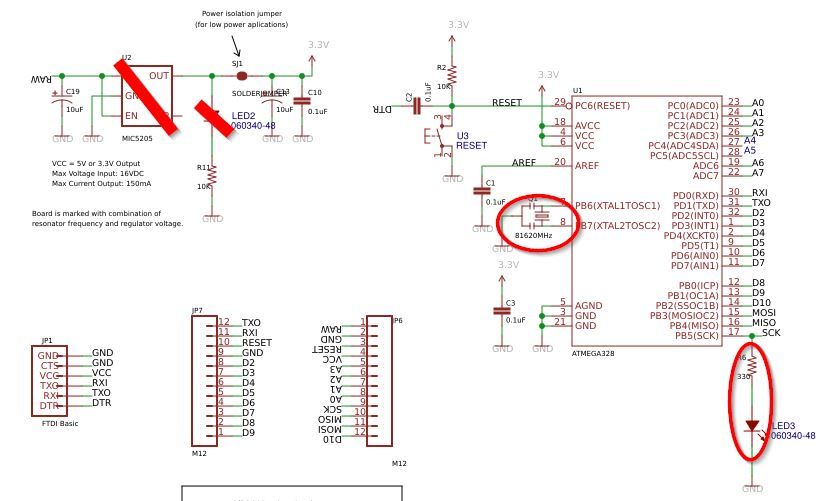
On the pro mini, there is a led connected to the SCK pin. I think that will add an extra of +-1mA when the radio is active?
But it has nothing to do with the sleep current of 133µA... -
Meanwhile I found following forum topic : https://forum.mysensors.org/topic/2067/my-slim-2aa-battery-node. Thanks @m26872 :-)
@mfalkvidd, I insist ;-) , if modifying these 'official' site articles turns out to be so difficult, can't a new section not be added like for example 'User experiences' or 'Advanced use' or 'Real world examples' or ... ?
Now we are obliged to read through hours of forum topics, hoping to find more information somewhere.
On one hand, this is of course instructive, but on the other hand it also wastes a lot of time looking for answers.
If we already had a starting list of some topics from experienced users, the learning curve would already be smaller.I started my battery crusade months ago by ordering some Arduino Pro Mini's from our Chinese supplier AliExpress following the official site article.
Because I could not obtain the given consumption of current, I began to search further.
Today after hours of searching and reading on the forum, I realize that this choice was actually not the right one.
I probably had better ordered the custom PCB from @m26872 and used a barebone 328P, or a Moteino or a Canique or...As far as the current of my pro mini is concerned, I'm stuck at a minimum of 133µA.
- pro mini without power led and power regulator
- refused using the MiniCore packet to 1.8V BOD and 1MHz internal
- board : ATmega328
- clock : internal 1 MHz
- BOD : BOD 1.8V
- EEPROM : EEPROM retained
- Variant : 328P / 328PA
- Bootloader : Yes (UART0)
- only one open or closed contact on pin D3 with external pull-up of 1M ohm
- radio is a RFM69HW
- sketch is using the mysensors sleep function with interrupt wake up (MySensors lib version 2.3.2).
To test if it was the radio module not completely sleeping and causing this consumption, I tested the same on a other pro mini (no power led and no power regulator, same refusing), without any external hardware, using the LowPower sketch from https://andreasrohner.at/posts/Electronics/How-to-modify-an-Arduino-Pro-Mini-clone-for-low-power-consumption/
==>same measurement : 133µA
So the radio module is not the raison!So what is the cause of this higher consumption?
The quality of the Chinese clone boards?
Or is there still external hardware on the board consuming some current? The external crystal still present for example?On the pro mini, there is a led connected to the SCK pin. I think that will add an extra of +-1mA when the radio is active?
But it has nothing to do with the sleep current of 133µA...@evb sorry for the late reply. I noticed your post earlier, but quickly realized I would need some time to catch up and grasp the full discussion. Now, when I finally have time to try to catch up, I realize that this is way beyond my capability of understanding. But if you provide instructions, I can paste them into the pages you deem relevant.
-
@evb sorry for the late reply. I noticed your post earlier, but quickly realized I would need some time to catch up and grasp the full discussion. Now, when I finally have time to try to catch up, I realize that this is way beyond my capability of understanding. But if you provide instructions, I can paste them into the pages you deem relevant.
@mfalkvidd
Ok, the first point is all about the image with the mention N/C
(see https://forum.mysensors.org/topic/4796/battery-powered-sensors/232)
We didn't know why this was set on the image.
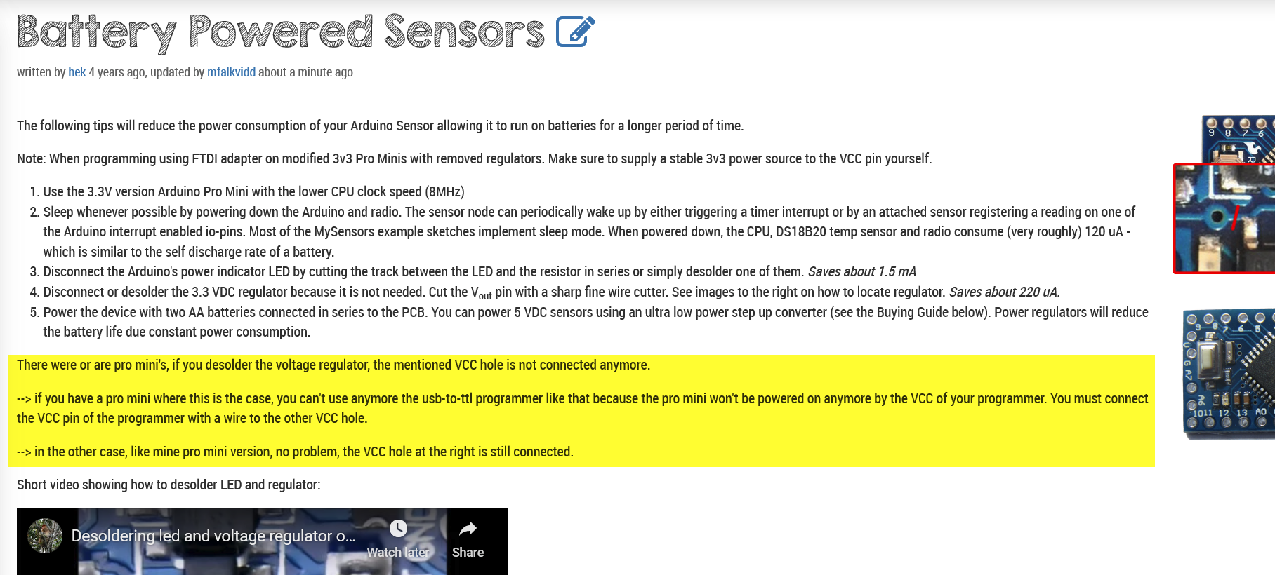
Now we do: there were or are pro mini's, if you desolder the voltage regulator, the mentioned VCC hole is not connected anymore.
--> if you have a pro mini where this is the case, you can't use anymore the usb-to-ttl programmer like that because the pro mini won't be powered on anymore by the VCC of your programmer. You must connect the VCC pin of the programmer with a wire to the other VCC hole.
--> in the other case, like mine pro mini version, no problem, the VCC hole at the right is still connected.The second point is all about the struggle to change/adapt/update existing site articles with updated/corrected/extended information :-)
I see that most site articles have the submenu 'Related Content'. In most articles this is empty. Can't we use that to link to forum topics with more information, I mean forum topics with a great deal of explanation or real world examples.
So that the reader has directly more information to read on the subject, without to be obliged to read hundreds of forum topics before finding the ones with adequate information.
For example I started with the pro mini, because mentioned in the site article, but today I'm aware that this was maybe not the way to go...
An example of such a forum topic is : https://forum.mysensors.org/topic/2067/my-slim-2aa-battery-node. -
@mfalkvidd
Ok, the first point is all about the image with the mention N/C
(see https://forum.mysensors.org/topic/4796/battery-powered-sensors/232)
We didn't know why this was set on the image.
Now we do: there were or are pro mini's, if you desolder the voltage regulator, the mentioned VCC hole is not connected anymore.
--> if you have a pro mini where this is the case, you can't use anymore the usb-to-ttl programmer like that because the pro mini won't be powered on anymore by the VCC of your programmer. You must connect the VCC pin of the programmer with a wire to the other VCC hole.
--> in the other case, like mine pro mini version, no problem, the VCC hole at the right is still connected.The second point is all about the struggle to change/adapt/update existing site articles with updated/corrected/extended information :-)
I see that most site articles have the submenu 'Related Content'. In most articles this is empty. Can't we use that to link to forum topics with more information, I mean forum topics with a great deal of explanation or real world examples.
So that the reader has directly more information to read on the subject, without to be obliged to read hundreds of forum topics before finding the ones with adequate information.
For example I started with the pro mini, because mentioned in the site article, but today I'm aware that this was maybe not the way to go...
An example of such a forum topic is : https://forum.mysensors.org/topic/2067/my-slim-2aa-battery-node.Thanks @evb. I have added the content:
As for the related content, I am not aware of any way to affect that part. To my knowledge, each page links to its own forum thread. For the battery page, it links to the forum thread we are currently posting in.
-
Meanwhile I found following forum topic : https://forum.mysensors.org/topic/2067/my-slim-2aa-battery-node. Thanks @m26872 :-)
@mfalkvidd, I insist ;-) , if modifying these 'official' site articles turns out to be so difficult, can't a new section not be added like for example 'User experiences' or 'Advanced use' or 'Real world examples' or ... ?
Now we are obliged to read through hours of forum topics, hoping to find more information somewhere.
On one hand, this is of course instructive, but on the other hand it also wastes a lot of time looking for answers.
If we already had a starting list of some topics from experienced users, the learning curve would already be smaller.I started my battery crusade months ago by ordering some Arduino Pro Mini's from our Chinese supplier AliExpress following the official site article.
Because I could not obtain the given consumption of current, I began to search further.
Today after hours of searching and reading on the forum, I realize that this choice was actually not the right one.
I probably had better ordered the custom PCB from @m26872 and used a barebone 328P, or a Moteino or a Canique or...As far as the current of my pro mini is concerned, I'm stuck at a minimum of 133µA.
- pro mini without power led and power regulator
- refused using the MiniCore packet to 1.8V BOD and 1MHz internal
- board : ATmega328
- clock : internal 1 MHz
- BOD : BOD 1.8V
- EEPROM : EEPROM retained
- Variant : 328P / 328PA
- Bootloader : Yes (UART0)
- only one open or closed contact on pin D3 with external pull-up of 1M ohm
- radio is a RFM69HW
- sketch is using the mysensors sleep function with interrupt wake up (MySensors lib version 2.3.2).
To test if it was the radio module not completely sleeping and causing this consumption, I tested the same on a other pro mini (no power led and no power regulator, same refusing), without any external hardware, using the LowPower sketch from https://andreasrohner.at/posts/Electronics/How-to-modify-an-Arduino-Pro-Mini-clone-for-low-power-consumption/
==>same measurement : 133µA
So the radio module is not the raison!So what is the cause of this higher consumption?
The quality of the Chinese clone boards?
Or is there still external hardware on the board consuming some current? The external crystal still present for example?On the pro mini, there is a led connected to the SCK pin. I think that will add an extra of +-1mA when the radio is active?
But it has nothing to do with the sleep current of 133µA... -
@evb said in 💬 Battery Powered Sensors:
As far as the current of my pro mini is concerned, I'm stuck at a minimum of 133µA.
So how low do you want to go? The original article mentions 120uA, so you seem to be pretty close to that value.
@Yveaux, after your comment, I did a search on '120' and you are right, it is even mentioned at the beginning of the article! :astonished:
I think I was to focused on the table of the Radio Power Consumption and on the forum topic https://forum.mysensors.org/topic/2067/my-slim-2aa-battery-node with a sleep consumption of:
The Sleep Mode Power Consumption
I measured the sleep mode current draw to be 1.5uA when it's set to interrupt wake up and 5.8uA when it's set to timer wake up.So the 133 µA is indeed very close to the 120µA mentioned!
So my node is functioning in the wanted consumption range, nothing wrong! :-)
Thanks. -
hek kindly explained to me how the related content works. Google generates it based on their magic. So that's why I was unable to find out how to affect it.
@mfalkvidd, thanks for searching this out :-)
So it is not really usable as a new section for linking adequate forum topics.Can we add then a new section called for example 'More (advanced) information' and put there more information for users wanting more (advanced) information? It can be extra text information or here for example a link to a advanced useful forum topic like I already mentioned.
What do you think about it?
My intention is to let others avoid the mistake I have made.
If we can provide some targeted links to topics that go deeper on the (basic) content of the article, then that is a win-win situation. The user gets his information and new ideas faster and the topic starter gets recognition for his work :-)
As a user and certainly a beginner, it is sometimes overwhelming to search the forum and to distinguish useful topics from unusable ones. -
Does enabled myDebug and some Serial.print statements (with serial port disconnected) affect power consumption of the node?
-
Does enabled myDebug and some Serial.print statements (with serial port disconnected) affect power consumption of the node?
-
If I remember correctly, writing to the serial port takes about 10s / baud rate for a single byte. That's a little unter 90µs at 115200 baud (common for Arduinos clocking 16 MHz at 5V) or about 1ms at 9600 baud (1MHz for 3V or less).
Imagine we are transmitting two messages per wake cycle and print another few custom lines to the serial port as well, that may result in about 500 bytes total. This would then add another 45ms on a fast clocking Arduino (115200 baud) or 0.5s (9600 baud) - plus likely some overhead - to the time the microcontroller spends in an active state.
According to the datasheet (p.312), an ATmega328P clocking at 1MHz consumes about 0.5mA in an active state at about 3V. So, from here on, you could calculate how drastically (or not) an additional ~0.1 - 0.7s of active time per wake cycle would impact the runtime of the battery.
Since it's possible to run a node for a year or much longer off a set of batteries if it doesn't send lots of messages every few minutes, I doubt you would be able to notice a difference between disabling debug prints or keeping them.
It is usually much more important to keep the current consumption during the power down phase as low as possible, than shedding off a few ms of active time.
-
@evb Hello. I am the maker of the Canique MK2 boards. I started just like you with the website from Andreas Rohner, desoldering the LED and desoldering the voltage regulator from such a chinese board until I realized this is the wrong way round.
As far as I recall, I've seen voltage regulators consume something in the order of 100uA when reverse powered. So that might be a hint.
The external crystal should not be drawing that much current. Using a 16MHz oscillator current can go as low as 4uA with watchdog enabled - in theory and on boards built with minimum consumption as a design goal.To your question regarding the SCK pin: yes, if it is connected to a LED every clock pulse on the SCK pin (when SPI is enabled) will make the LED draw current.
You also have these kinds of troubles (SPI drawing too much current when active or inactive) with chinese boards having a BME280 on them for example. If you have high quality standards, the stock chinese boards won't fit your needs.
-
Meanwhile I found following forum topic : https://forum.mysensors.org/topic/2067/my-slim-2aa-battery-node. Thanks @m26872 :-)
@mfalkvidd, I insist ;-) , if modifying these 'official' site articles turns out to be so difficult, can't a new section not be added like for example 'User experiences' or 'Advanced use' or 'Real world examples' or ... ?
Now we are obliged to read through hours of forum topics, hoping to find more information somewhere.
On one hand, this is of course instructive, but on the other hand it also wastes a lot of time looking for answers.
If we already had a starting list of some topics from experienced users, the learning curve would already be smaller.I started my battery crusade months ago by ordering some Arduino Pro Mini's from our Chinese supplier AliExpress following the official site article.
Because I could not obtain the given consumption of current, I began to search further.
Today after hours of searching and reading on the forum, I realize that this choice was actually not the right one.
I probably had better ordered the custom PCB from @m26872 and used a barebone 328P, or a Moteino or a Canique or...As far as the current of my pro mini is concerned, I'm stuck at a minimum of 133µA.
- pro mini without power led and power regulator
- refused using the MiniCore packet to 1.8V BOD and 1MHz internal
- board : ATmega328
- clock : internal 1 MHz
- BOD : BOD 1.8V
- EEPROM : EEPROM retained
- Variant : 328P / 328PA
- Bootloader : Yes (UART0)
- only one open or closed contact on pin D3 with external pull-up of 1M ohm
- radio is a RFM69HW
- sketch is using the mysensors sleep function with interrupt wake up (MySensors lib version 2.3.2).
To test if it was the radio module not completely sleeping and causing this consumption, I tested the same on a other pro mini (no power led and no power regulator, same refusing), without any external hardware, using the LowPower sketch from https://andreasrohner.at/posts/Electronics/How-to-modify-an-Arduino-Pro-Mini-clone-for-low-power-consumption/
==>same measurement : 133µA
So the radio module is not the raison!So what is the cause of this higher consumption?
The quality of the Chinese clone boards?
Or is there still external hardware on the board consuming some current? The external crystal still present for example?On the pro mini, there is a led connected to the SCK pin. I think that will add an extra of +-1mA when the radio is active?
But it has nothing to do with the sleep current of 133µA...@evb little info regarding the LED on the SCK pin.
Assuming it is a red LED with a forward voltage of 1.8V, considering the chip is powered with 3.3V and considering the 330 Ohm resistor in series with the LED, the additional current draw when SCK goes high should be about 4.5mA.