💬 Battery Powered Sensors


  • Admin

    This thread contains comments for the article "Battery Powered Sensors" posted on MySensors.org.


  • Hardware Contributor

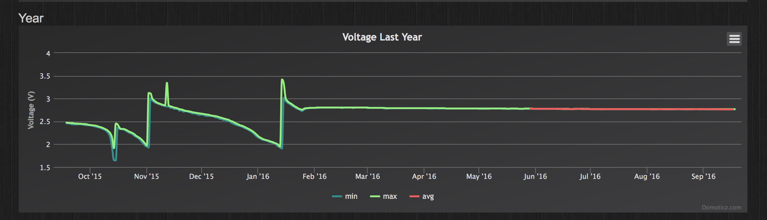
    Here is a view of a node running exactly 1year. The effect of a bad radio is seen here as the fast voltage drops. I had a very low charged battery to start with, replaced it with new batteries which also discharged fast, and replaced both batteries and the radio. Since mid january 2016 the node has been running as expected. My guess is that this combo will run for 2 years (given how it has been working the past 9 months).

    This node measures battery voltage, temperature and humidity and sends 3 messages about every 5 minutes.

    0_1474202873202_Screen Shot 2016-09-18 at 14.41.30.png

    And here is the battery measurement of the second node that went "online" the same day (18/sep/2015, with a good radio, and similarly used batteries from the start). This node sends very few messages (at least 1 every 24 hours, and when one of 3 contacts are opened). Most days it just sends 1 message.

    0_1474203476121_Screen Shot 2016-09-18 at 14.55.05.png

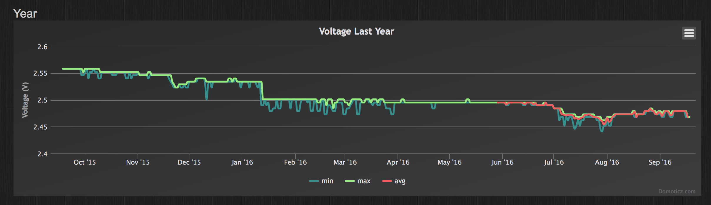
    So even with batteries already at a low level, you can make useful nodes using the MySensors setup 🙂


  • This post is deleted!


  • Sorry, where do you measure the power when it is in sleep mode? ie, where do you put your multimeter probes.


  • Mod

    @Nicklas-Starkel you put them in serial. So:
    battery+ to multimeter- (set to uA mode)
    Multimeter+ to vcc
    Battery- to gnd

    You need a very sensitive multimeter though. Most multimeters won't be able to measure low current reliably.


  • @mfalkvidd that's what I thought! I see that I'm getting 3.4V in the multimeter but my pro mini nor nano will start up (I have not removed the LEDs so they should light up).
    If I use more V (6.8V) I put in via RAW on the PRO mini, and I can see teh voltage, but the same thing, it's not starting up, hmmm I wonder what rookie mistake I'm doing!


  • Mod

    @Nicklas-Starkel sounds like you have the multimeter set to measure voltage instead of current. Which multimeter model are you using? Could you post a photo? There is usually a dial that can be turned to switch mode. Many multimeters also require moving one of the probes to a different connector (on the multimeter itself).


  • @mfalkvidd , it was too late at night for me.
    I had it at current but it didn't show anything. So without thinking I put it at voltage.
    And the problem with not showing anything when I had it at current was I had blown the internal multimeter fuse some days ago.
    Ehrmm.. yes. move along, nothing to see here 🙂


  • Mod

    @Nicklas-Starkel great that you figured out what was wrong


  • Hi, I built this circuit and arduino reads 1.11 V or 33%. I've new batteries and multimeter reads 3.10 volts. Do you know what could be wrong? I'm using 1M and 470k resistors on pin A0.


  • Hardware Contributor

    Hello,

    Did you put this command in the setup sketch ?

    analogReference(INTERNAL);


  • @tonnerre33, yes I've analogReference(INTERNAL); in setup()


  • Hardware Contributor

    It's normal to have 1.1V on A0 when you have 3.3V on your batteries.

    Where did you get the 1.11V value ? In the serial print or with your multimeter ?
    If you read the value with the serial print, which variable is it (sensorValue or batteryV) ?


  • @tonnerre33 in the serial print and MySensor MQTT gateway


  • @tonnerre33, I'm trying to build arduio that can run on 2 AA batteries. I'm using MySensors for library and building arduino circuit based on this https://openhomeautomation.net/arduino-battery/


  • Hardware Contributor

    Can you post the logs of your node and the skech used ?


  • Mod

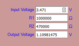
    @bjacobt https://www.mysensors.org/build/battery#measuring-and-reporting-battery-level describes how the battery voltage is calculated and the example sketch has code for doing the calculation. Looks like you've missed reading this part:

       // 1M, 470K divider across battery and using internal ADC ref of 1.1V
       // Sense point is bypassed with 0.1 uF cap to reduce noise at that point
       // ((1e6+470e3)/470e3)*1.1 = Vmax = 3.44 Volts
       // 3.44/1023 = Volts per bit = 0.003363075
    ...
    float batteryV  = sensorValue * 0.003363075;


  • @tonnerre33
    Here are the logs from Arduino Serial console

    Starting sensor (RNNNA-, 2.0.0)
    TSM:INIT
    TSM:RADIO:OK
    TSP:ASSIGNID:OK (ID=101)
    TSM:FPAR
    TSP:MSG:SEND 101-101-255-255 s=255,c=3,t=7,pt=0,l=0,sg=0,ft=0,st=bc:
    TSP:MSG:READ 0-0-101 s=255,c=3,t=8,pt=1,l=1,sg=0:0
    TSP:MSG:FPAR RES (ID=0, dist=0)
    TSP:MSG:PAR OK (ID=0, dist=1)
    TSM:FPAR:OK
    TSM:ID
    TSM:CHKID:OK (ID=101)
    TSM:UPL
    TSP:PING:SEND (dest=0)
    TSP:MSG:SEND 101-101-0-0 s=255,c=3,t=24,pt=1,l=1,sg=0,ft=0,st=ok:1
    TSP:MSG:READ 0-0-101 s=255,c=3,t=25,pt=1,l=1,sg=0:1
    TSP:MSG:PONG RECV (hops=1)
    TSP:CHKUPL:OK
    TSM:UPL:OK
    TSM:READY
    TSP:MSG:SEND 101-101-0-0 s=255,c=3,t=15,pt=6,l=2,sg=0,ft=0,st=ok:0100
    !TSP:MSG:SEND 101-101-0-0 s=255,c=0,t=17,pt=0,l=5,sg=0,ft=0,st=fail:2.0.0
    TSP:MSG:SEND 101-101-0-0 s=255,c=3,t=6,pt=1,l=1,sg=0,ft=1,st=ok:0
    TSP:MSG:READ 0-0-101 s=255,c=3,t=15,pt=6,l=2,sg=0:0100
    TSP:MSG:SEND 101-101-0-0 s=255,c=3,t=11,pt=0,l=13,sg=0,ft=0,st=ok:Battery Meter
    TSP:MSG:SEND 101-101-0-0 s=255,c=3,t=12,pt=0,l=3,sg=0,ft=0,st=ok:1.0
    Request registration...
    TSP:MSG:SEND 101-101-0-0 s=255,c=3,t=26,pt=1,l=1,sg=0,ft=0,st=ok:2
    TSP:MSG:READ 0-0-101 s=255,c=3,t=27,pt=1,l=1,sg=0:1
    Node registration=1
    Init complete, id=101, parent=0, distance=1, registration=1
    330
    Battery Voltage: 1.11 V
    Battery percent: 33 %
    TSP:MSG:SEND 101-101-0-0 s=255,c=3,t=0,pt=1,l=1,sg=0,ft=0,st=ok:33
    

    The sketch used is this:

    /**
     * The MySensors Arduino library handles the wireless radio link and protocol
     * between your home built sensors/actuators and HA controller of choice.
     * The sensors forms a self healing radio network with optional repeaters. Each
     * repeater and gateway builds a routing tables in EEPROM which keeps track of the
     * network topology allowing messages to be routed to nodes.
     *
     * Created by Henrik Ekblad <henrik.ekblad@mysensors.org>
     * Copyright (C) 2013-2015 Sensnology AB
     * Full contributor list: https://github.com/mysensors/Arduino/graphs/contributors
     *
     * Documentation: http://www.mysensors.org
     * Support Forum: http://forum.mysensors.org
     *
     * This program is free software; you can redistribute it and/or
     * modify it under the terms of the GNU General Public License
     * version 2 as published by the Free Software Foundation.
     *
     *******************************
     *
     * DESCRIPTION
     *
     * This is an example that demonstrates how to report the battery level for a sensor
     * Instructions for measuring battery capacity on A0 are available here:
     * http://www.mysensors.org/build/battery
     * 
     */
    
    
    #define MY_NODE_ID  101
    
    // Enable debug prints to serial monitor
    #define MY_DEBUG 
    
    // Enable and select radio type attached
    #define MY_RADIO_NRF24
    //#define MY_RADIO_RFM69
    
    #include <MySensors.h>


    int BATTERY_SENSE_PIN = A0;  // select the input pin for the battery sense point
    
    unsigned long SLEEP_TIME = 100000;  // sleep time between reads (seconds * 1000 milliseconds)
    int oldBatteryPcnt = 0;
    
    void setup()  
    {
       // use the 1.1 V internal reference
    #if defined(__AVR_ATmega2560__)
       analogReference(INTERNAL1V1);
    #else
       analogReference(INTERNAL);
    #endif
    }
    
    void presentation() {
       // Send the sketch version information to the gateway and Controller
       sendSketchInfo("Battery Meter", "1.0");
    }
    
    void loop()
    {
       // get the battery Voltage
       int sensorValue = analogRead(BATTERY_SENSE_PIN);
       #ifdef MY_DEBUG
       Serial.println(sensorValue);
       #endif
    
       // 1M, 470K divider across battery and using internal ADC ref of 1.1V
       // Sense point is bypassed with 0.1 uF cap to reduce noise at that point
       // ((1e6+470e3)/470e3)*1.1 = Vmax = 3.44 Volts
       // 3.44/1023 = Volts per bit = 0.003363075
    
       int batteryPcnt = sensorValue / 10;
    
       #ifdef MY_DEBUG
       float batteryV  = sensorValue * 0.003363075;
       Serial.print("Battery Voltage: ");
       Serial.print(batteryV);
       Serial.println(" V");
    
       Serial.print("Battery percent: ");
       Serial.print(batteryPcnt);
       Serial.println(" %");
       #endif
    
       if (oldBatteryPcnt != batteryPcnt) {
         // Power up radio after sleep
         sendBatteryLevel(batteryPcnt);
         oldBatteryPcnt = batteryPcnt;
       }
       sleep(SLEEP_TIME);
    }```
    
    What I see on the gateway is:


    mysGateway: TSF:MSG:READ,101-101-255,s=255,c=3,t=7,pt=0,l=0,sg=0:
    mysGateway: TSF:MSG:BC
    mysGateway: TSF:MSG:FPAR REQ,ID=101
    mysGateway: TSF:PNG:SEND,TO=0
    mysGateway: TSF:CKU:OK
    mysGateway: TSF:MSG:GWL OK
    mysGateway: TSF:MSG:SEND,0-0-101-101,s=255,c=3,t=8,pt=1,l=1,sg=0,ft=0,st=OK:0
    mysGateway: TSF:MSG:READ,101-101-0,s=255,c=3,t=24,pt=1,l=1,sg=0:1
    mysGateway: TSF:MSG:PINGED,ID=101,HP=1
    mysGateway: TSF:MSG:SEND,0-0-101-101,s=255,c=3,t=25,pt=1,l=1,sg=0,ft=0,st=OK:1
    mysGateway: TSF:MSG:READ,101-101-0,s=255,c=3,t=15,pt=6,l=2,sg=0:0100
    mysGateway: !TSF:MSG:SEND,0-0-101-101,s=255,c=3,t=15,pt=6,l=2,sg=0,ft=0,st=NACK:0100
    mysGateway: TSF:MSG:READ,101-101-0,s=255,c=3,t=6,pt=1,l=1,sg=0:0
    mysGateway: Sending message on topic: mysensors-out/101/255/3/0/6
    mysGateway: TSF:MSG:READ,101-101-255,s=255,c=3,t=7,pt=0,l=0,sg=0:
    mysGateway: TSF:MSG:BC
    mysGateway: TSF:MSG:FPAR REQ,ID=101
    mysGateway: TSF:CKU:OK,FCTRL
    mysGateway: TSF:MSG:GWL OK
    mysGateway: TSF:MSG:SEND,0-0-101-101,s=255,c=3,t=8,pt=1,l=1,sg=0,ft=0,st=OK:0
    mysGateway: TSF:MSG:READ,101-101-0,s=255,c=3,t=24,pt=1,l=1,sg=0:1
    mysGateway: TSF:MSG:PINGED,ID=101,HP=1
    mysGateway: TSF:MSG:SEND,0-0-101-101,s=255,c=3,t=25,pt=1,l=1,sg=0,ft=0,st=OK:1
    mysGateway: TSF:MSG:READ,101-101-0,s=255,c=3,t=15,pt=6,l=2,sg=0:0100
    mysGateway: !TSF:MSG:SEND,0-0-101-101,s=255,c=3,t=15,pt=6,l=2,sg=0,ft=0,st=NACK:0100
    mysGateway: TSF:MSG:READ,101-101-0,s=255,c=3,t=6,pt=1,l=1,sg=0:0
    mysGateway: Sending message on topic: mysensors-out/101/255/3/0/6
    mysGateway: TSF:MSG:READ,101-101-0,s=255,c=3,t=11,pt=0,l=13,sg=0:Battery Meter
    mysGateway: Sending message on topic: mysensors-out/101/255/3/0/11
    mysGateway: TSF:MSG:READ,101-101-0,s=255,c=3,t=12,pt=0,l=3,sg=0:1.0
    mysGateway: Sending message on topic: mysensors-out/101/255/3/0/12
    mysGateway: TSF:MSG:READ,101-101-0,s=255,c=3,t=26,pt=1,l=1,sg=0:2
    mysGateway: TSF:MSG:SEND,0-0-101-101,s=255,c=3,t=27,pt=1,l=1,sg=0,ft=0,st=OK:1
    mysGateway: TSF:MSG:READ,101-101-0,s=255,c=3,t=0,pt=1,l=1,sg=0:33
    mysGateway: Sending message on topic: mysensors-out/101/255/3/0/0```

    Thank for your help!
    Jacob


  • hi @mfalkvidd,

    Do you mind clarifying a bit, I've done sensorValue * 0.003363075

    analogRead(BATTERY_SENSE_PIN);
    

    Gives me 330, so
    330 * 0.003363075 = 1.10981475 volts

    Thank You!
    Jacob


  • Mod

    @bjacobt hmm. Yes, you are correct. The calculation seem a bit strange.
    Using this calculator I entered
    output 1.10981475 V
    R1 1000000
    R2 470000
    Which gives a battery voltage of 3.471V
    0_1478095026919_voltage.png

    Looks like the calculations in the sketch are wrong? Or at least confusing 🙂 I'm pretty lost.


  • Hardware Contributor

    analogRead(BATTERY_SENSE_PIN);
    

    must give you 1023 and not 330.
    For me it's a problem of value resistance or analogReference.

    Try to add this

    analogReference(INTERNAL);
    sensorValue = analogRead(BATTERY_SENSE_PIN);
      #ifdef MY_DEBUG
     Serial.print("Value A0 before force reference: ");
     Serial.print(sensorValue);
    #endif
    delay(10000);
    sensorValue = analogRead(BATTERY_SENSE_PIN);
      #ifdef MY_DEBUG
     Serial.print("Value A0 after force reference: ");
     Serial.print(sensorValue);
    #endif
    

    Just after this existing code :

       #ifdef MY_DEBUG
       Serial.println(sensorValue);
       #endif
    

    And plz send me the logs of the node 😉


  • @tonnerre33 Its still the same

    Starting sensor (RNNNA-, 2.0.0)
    TSM:INIT
    TSM:RADIO:OK
    TSP:ASSIGNID:OK (ID=101)
    TSM:FPAR
    TSP:MSG:SEND 101-101-255-255 s=255,c=3,t=7,pt=0,l=0,sg=0,ft=0,st=bc:
    TSP:MSG:READ 0-0-101 s=255,c=3,t=8,pt=1,l=1,sg=0:0
    TSP:MSG:FPAR RES (ID=0, dist=0)
    TSP:MSG:PAR OK (ID=0, dist=1)
    TSM:FPAR:OK
    TSM:ID
    TSM:CHKID:OK (ID=101)
    TSM:UPL
    TSP:PING:SEND (dest=0)
    TSP:MSG:SEND 101-101-0-0 s=255,c=3,t=24,pt=1,l=1,sg=0,ft=0,st=ok:1
    TSP:MSG:READ 0-0-101 s=255,c=3,t=25,pt=1,l=1,sg=0:1
    TSP:MSG:PONG RECV (hops=1)
    TSP:CHKUPL:OK
    TSM:UPL:OK
    TSM:READY
    TSP:MSG:SEND 101-101-0-0 s=255,c=3,t=15,pt=6,l=2,sg=0,ft=0,st=ok:0100
    TSP:MSG:SEND 101-101-0-0 s=255,c=0,t=17,pt=0,l=5,sg=0,ft=0,st=ok:2.0.0
    TSP:MSG:SEND 101-101-0-0 s=255,c=3,t=6,pt=1,l=1,sg=0,ft=0,st=ok:0
    TSP:MSG:READ 0-0-101 s=255,c=3,t=15,pt=6,l=2,sg=0:0100
    TSP:MSG:SEND 101-101-0-0 s=255,c=3,t=11,pt=0,l=13,sg=0,ft=0,st=ok:Battery Meter
    TSP:MSG:SEND 101-101-0-0 s=255,c=3,t=12,pt=0,l=3,sg=0,ft=0,st=ok:1.0
    Request registration...
    TSP:MSG:SEND 101-101-0-0 s=255,c=3,t=26,pt=1,l=1,sg=0,ft=0,st=ok:2
    TSP:MSG:READ 0-0-101 s=255,c=3,t=27,pt=1,l=1,sg=0:1
    Node registration=1
    Init complete, id=101, parent=0, distance=1, registration=1
    330
    Value A0 before force reference: 327
    Value A0 after force reference: 329
    Battery Voltage: 1.11 V
    Battery percent: 32 %
    TSP:MSG:SEND 101-101-0-0 s=255,c=3,t=0,pt=1,l=1,sg=0,ft=0,st=ok:32

    /**
     * The MySensors Arduino library handles the wireless radio link and protocol
     * between your home built sensors/actuators and HA controller of choice.
     * The sensors forms a self healing radio network with optional repeaters. Each
     * repeater and gateway builds a routing tables in EEPROM which keeps track of the
     * network topology allowing messages to be routed to nodes.
     *
     * Created by Henrik Ekblad <henrik.ekblad@mysensors.org>
     * Copyright (C) 2013-2015 Sensnology AB
     * Full contributor list: https://github.com/mysensors/Arduino/graphs/contributors
     *
     * Documentation: http://www.mysensors.org
     * Support Forum: http://forum.mysensors.org
     *
     * This program is free software; you can redistribute it and/or
     * modify it under the terms of the GNU General Public License
     * version 2 as published by the Free Software Foundation.
     *
     *******************************
     *
     * DESCRIPTION
     *
     * This is an example that demonstrates how to report the battery level for a sensor
     * Instructions for measuring battery capacity on A0 are available here:
     * http://www.mysensors.org/build/battery
     * 
     */
    
    
    #define MY_NODE_ID  101
    
    // Enable debug prints to serial monitor
    #define MY_DEBUG 
    
    // Enable and select radio type attached
    #define MY_RADIO_NRF24
    //#define MY_RADIO_RFM69
    
    #include <MySensors.h>


    int BATTERY_SENSE_PIN = A0;  // select the input pin for the battery sense point
    
    unsigned long SLEEP_TIME = 100000;  // sleep time between reads (seconds * 1000 milliseconds)
    int oldBatteryPcnt = 0;
    
    void setup()  
    {
       // use the 1.1 V internal reference
    #if defined(__AVR_ATmega2560__)
       analogReference(INTERNAL1V1);
    #else
       analogReference(INTERNAL);
    #endif
    }
    
    void presentation() {
       // Send the sketch version information to the gateway and Controller
       sendSketchInfo("Battery Meter", "1.0");
    }
    
    void loop()
    {
       // get the battery Voltage
       int sensorValue = analogRead(BATTERY_SENSE_PIN);
       #ifdef MY_DEBUG
       Serial.println(sensorValue);
       #endif
    
    analogReference(INTERNAL);
    sensorValue = analogRead(BATTERY_SENSE_PIN);
      #ifdef MY_DEBUG
     Serial.print("Value A0 before force reference: ");
     Serial.println(sensorValue);
    #endif
    delay(10000);
    sensorValue = analogRead(BATTERY_SENSE_PIN);
      #ifdef MY_DEBUG
     Serial.print("Value A0 after force reference: ");
     Serial.println(sensorValue);
    #endif
       
    
       // 1M, 470K divider across battery and using internal ADC ref of 1.1V
       // Sense point is bypassed with 0.1 uF cap to reduce noise at that point
       // ((1e6+470e3)/470e3)*1.1 = Vmax = 3.44 Volts
       // 3.44/1023 = Volts per bit = 0.003363075
    
       int batteryPcnt = sensorValue / 10;
    
       #ifdef MY_DEBUG
       float batteryV  = sensorValue * 0.003363075;
       Serial.print("Battery Voltage: ");
       Serial.print(batteryV);
       Serial.println(" V");
    
       Serial.print("Battery percent: ");
       Serial.print(batteryPcnt);
       Serial.println(" %");
       #endif
    
       if (oldBatteryPcnt != batteryPcnt) {
         // Power up radio after sleep
         sendBatteryLevel(batteryPcnt);
         oldBatteryPcnt = batteryPcnt;
       }
       sleep(SLEEP_TIME);
    }```

  • Hardware Contributor

    Ok it's not a problem with the analogReference, you can delete this part of code.
    Did you control your resistance value and did you do this schema ?
    alt text


  • Hi,
    I'm sorry what do you mean by "control your resistance value"

    this is my circuit,

    1M resistor to +V rail, 470K resistor to GND and middle point to A0.

    0_1478097209731_IMG_1543.JPG ,


  • Hardware Contributor

    Ok try to remove the jumper between V+ and AREF


  • @tonnerre33 That was it!

    I'm getting Battery Voltage: 3.10 V
    Battery percent: 92 %

    Thank you so much 🙂

    Starting sensor (RNNNA-, 2.0.0)
    TSM:INIT
    TSM:RADIO:OK
    TSP:ASSIGNID:OK (ID=101)
    TSM:FPAR
    TSP:MSG:SEND 101-101-255-255 s=255,c=3,t=7,pt=0,l=0,sg=0,ft=0,st=bc:
    TSP:MSG:READ 0-0-101 s=255,c=3,t=8,pt=1,l=1,sg=0:0
    TSP:MSG:FPAR RES (ID=0, dist=0)
    TSP:MSG:PAR OK (ID=0, dist=1)
    TSM:FPAR:OK
    TSM:ID
    TSM:CHKID:OK (ID=101)
    TSM:UPL
    TSP:PING:SEND (dest=0)
    TSP:MSG:SEND 101-101-0-0 s=255,c=3,t=24,pt=1,l=1,sg=0,ft=0,st=ok:1
    TSP:MSG:READ 0-0-101 s=255,c=3,t=25,pt=1,l=1,sg=0:1
    TSP:MSG:PONG RECV (hops=1)
    TSP:CHKUPL:OK
    TSM:UPL:OK
    TSM:READY
    TSP:MSG:SEND 101-101-0-0 s=255,c=3,t=15,pt=6,l=2,sg=0,ft=0,st=ok:0100
    !TSP:MSG:SEND 101-101-0-0 s=255,c=0,t=17,pt=0,l=5,sg=0,ft=0,st=fail:2.0.0
    TSP:MSG:SEND 101-101-0-0 s=255,c=3,t=6,pt=1,l=1,sg=0,ft=1,st=ok:0
    TSP:MSG:SEND 101-101-0-0 s=255,c=3,t=11,pt=0,l=13,sg=0,ft=0,st=ok:Battery Meter
    TSP:MSG:SEND 101-101-0-0 s=255,c=3,t=12,pt=0,l=3,sg=0,ft=0,st=ok:1.0
    Request registration...
    TSP:MSG:SEND 101-101-0-0 s=255,c=3,t=26,pt=1,l=1,sg=0,ft=0,st=ok:2
    TSP:MSG:READ 0-0-101 s=255,c=3,t=27,pt=1,l=1,sg=0:1
    Node registration=1
    Init complete, id=101, parent=0, distance=1, registration=1
    922
    Value A0 before force reference: 924
    Value A0 after force reference: 923
    Battery Voltage: 3.10 V
    Battery percent: 92 %
    TSP:MSG:SEND 101-101-0-0 s=255,c=3,t=0,pt=1,l=1,sg=0,ft=0,st=ok:92


  • can Li 18650 3.7 batteries be used as they are rechargeable ? knowing the max voltage at full might reach 4.1-4.2v ? maybe keeping the voltage regulator ?


  • Mod

    @Meshx86 yes they can be used but as you've already identified the nrf (and maybe other components) will need to be protected from the high voltage when the battery is full.

    The self-discharge rate of li-ion is higher than alkaline batteries which might affect how long the node can run before it needs charging.


  • Hi,
    I just built the circuit which is explained in the thread with a Pro Mini 3.3 8 mHz
    So far so good, I can read the voltage of the battery etc but my problem is, it consumes about 1.2 mA while in sleep, this is about factor 10 of the findings from the thread.
    I just copied the code 1:1
    Any glue what could be wrong or what get others with that setup? The Arduino is not modified at all.

    Thanks
    SJ


  • @parachutesj you have to modify the pro mini. Remove the power led according to instructions!


  • @Nicklas-Starkel thank you. If one could read...
    I read the description again and thought that it should be 120uA stock and when removing LED and regulator it will even go down further but thinking about it, how should at base 120 uA and removing LED save additional 1.5mA???? LOL, sorry was a long day.

    My Fluke reads 0.044 mA in sleep now (without LED). Sweet!


  • Another battery related question that I really do not understand.
    Are there different versions on how to read battery consumption?

    I see some sketches uses:

    long readVcc() {
      long result;
      // Read 1.1V reference against AVcc
      ADMUX = _BV(REFS0) | _BV(MUX3) | _BV(MUX2) | _BV(MUX1);
      delay(2); // Wait for Vref to settle
      noInterrupts ();
      // start the conversion
      ADCSRA |= _BV (ADSC) | _BV (ADIE);
      set_sleep_mode (SLEEP_MODE_ADC);    // sleep during sample
      interrupts ();
      sleep_mode (); 
      // reading should be done, but better make sure
      // maybe the timer interrupt fired 
      while (bit_is_set(ADCSRA,ADSC));
      result = ADCL;
      result |= ADCH<<8;
      result = 1126400L / result; // Back-calculate AVcc in mV```
    

    However some (like the original one in this thread) uses:

     int sensorValue = analogRead(BATTERY_SENSE_PIN);
    

    Is it due to different libraries or maybe it is the same but just programming wise different?


  • If you are using the first sketch you dont have to use a seperate pin to measure the input voltage. There are also no resistors.

    You can run this on a bare ATmega with minimal hardware.


  • @gloob thanks!
    One would think running with no resistors and not using a separate PIN would be better.

    @hek or @mfalkvidd , any comments as to why the original sketch is preferred over the other 'way' in this article?


  • Admin


  • @hek , I've read that post several times 🙂
    Since it was so outdated (2 years) I naturally assumed the 'battery powering article' was a newer way to do it (especially since mys2.0).
    Also, the post you linked to is attributed if you use no voltage regulator.
    And in the article this is also one of the things you are recommended to remove, hence making it even more confusing as to why the article describes another way than the post.


  • i just want to get this once and for all, so others coming by gets it directly instead of going through all the 2 threads posts, please correct me if i am wrong:

    1- using the voltage divider is needed if there is a voltage regulator / booster where where VBatt != Vcc.
    2- using the voltage regulator is not needed if the voltage regulator is removed / no booster is used (powering directly from 2 x AA batteries) where VBatt == Vcc.

    *I've noticed the 2nd method requires inputting battrie's DMM measured values vs arduino ones for correction, is this a down side if you need to change the battery later on ? or is it just programmed once ? and does the 1st method rquirs these corrections too ?

    Cheers


  • Hardware Contributor

    @Meshx86
    actually, you need a voltage divider if the voltage to be measured is above the maximum allowed by the processor at the speed you are running it.

    If Vcc is 5V, then any voltage above 5V should be measured via a voltage divider.
    If Vcc is 3.3V same principle, but you could get away with measuring 5V directly (would not kill the processor), but your values may be off.


  • @GertSanders following the instructions of this post suggest using Alkaline batteries (apparently Li-ion aren't a good idea for sensor nodes ?! plus they are expensive), the optimal solution would be using 2 x AA batteries as some ans this post suggested.

    I believe there is no way 2 x AA batteries in series would measure anywhere near 3.3v, the max i measured with brand new batteries was 3.2v.

    my major concern is:
    would i still need to the do the voltage corrections when using the voltage divider ? if so, does that need to be reprogrammed every time you replace the battery ?

    sorry to bring this again @Yveaux @axillent


  • Hardware Contributor

    @Meshx86
    No problem to ask. I use the intern measurement method, which uses the internal 1.1V reference of the atmega328, so even if the Vcc value changes from 3.2V -> 2.6V, the reference will always be 1.1V, and the internal method allows you to calculate the actual measured battery voltage based on a difference with the reference, even with a declining value on Vcc (if powered by the same batteries).


  • @GertSanders sorry mate, am more of a software guy..

    according to the lib i've seen and @Yveaux's example for the internal method, at the begining you need to define a corrective value :

    const float VccCorrection = 1.0/1.0;  // Measured Vcc by multimeter divided by reported Vcc
    
    Vcc vcc(VccCorrection);
    

    is this necessary for an accurate reading ? and is the corrective value need to be just entered once (like a calibration per arduino) or need to be reconfigured every time you replace a battery ?


  • Good article/site on why Alkaline is the best way to go for Mysensors nodes 🙂
    http://batteryuniversity.com/learn/article/elevating_self_discharge


  • Hardware Contributor

    @Meshx86
    The corrective value is needed every time you change a battery, AND if you need high accuracy.
    On my battery based nodes I do not have a need for absolute accuracy, I just need to see the trend of the Vcc value.
    Changing the battery happens every 12-24 months (depends on the use), so I'm not very interested in absolute accuracy. If you need real accurate measuring, I would suggest a real Analog-To_Digital chip.


  • @GertSanders thanks , i think accuracy isn't a deal breaker, i believe everyone's concern is to just know when the batteries need to be replaced (hopefully that can be done without specifying the voltage correction).


  • Mod

    @Meshx86 ok, being quoted so many times I can also add my 5 cents 😄
    The correction factor is optional. You can use it to improve the measured voltage, as the internal voltage reference is only accurate up to so many percentage (have to look up the number). It is unique to the arduino used.
    This factor should however not depend on the batteries, possibly on environmental factors (e.g. Temperature)


  • @Yveaux one last, i promise 😛

    if max battery voltage is actually 3.2v, does that mean that the battery percentage would show 100% for quite sometime before it starts dropping below 3.0v (assuming vmax is set to 3.0) ? or would it increase the inaccuracy gap ?


  • Mod

    @Meshx86 the function Read_Perc() takes a boolean as 3rd parameter. Default it's true, which means the result is clipped to 0..100% range.
    So, if maximum is set to 3v, and you are currently above it, it will report 100% until you drop below 3v.


  • Hero Member

    @Nicklas-Starkel The article mostly talks about rechargeable batteries. I prefer non rechargeable Lithium batteries (like coin cells) for their energy density and very low self discharge.
    My major concern with (cheap) alkaline batteries is their leakage of aggressive chemicals. I had to trash my first nodes because of this 😒


  • @AWI in the first part it states:
    "Primary cells such as lithium-metal and alkaline retain the stored energy best, and can be kept in storage for several years."
    So you are correct and between Alkaline and Lithium-metal maybe the latter would be best. 🙂
    I have no experience with coin cells and will do some testing with them as soon as I can.
    Since this is the battery article, would you please tell me what you use and how you use it. What you expected and if the batteries lived up to your expectations. Would be cool to know as you've had more experience then me (and many like me)!


  • Hardware Contributor

    @AWI I'm agree with you but coin cells have less capacity. The difference of the self discharge between coin cells and alkaline is not important (1% vs 2%), but the capacity and size are.

    Here is a link with the Battery self-discharge rates :
    http://www.gammon.com.au/power


  • Hero Member

    @Nicklas-Starkel I mostly use a 'large' version lithium cell i.e. Cr123. These were used large in compact camera's and have a huge capacity and very little self discharge. My best example is the sensor in the fridge which measure temp and humidity every 10 secs and sends with nrf24l01 (MySensors of course). This one runs for almost two years now and has a stable 3.02V since the second month.

    The coin cells need special care a these have a high 'internal resistance'. You need to be careful with designing the sketch so that the load is as short and light as possible.

    There are some of my postings on this site which elaborate on the subject. (I'm on a mobile phone right now...)


  • @AWI OMG there is so many options when you look at it!
    I think it all boils down to design (size) or money.
    Normal AA roughly 0.3EUR/pc are quite large but OK power but cheap
    CR123 roughly 2.5EUR/pc are quite small and OK power but expensive
    Coin cell roughly 1EUR/pc and they are the smallest but not packing a good punch while being semi cheap/expensive.

    Obviously I have to build one node with each and put them in flowerpots around the flat to see in in action 🙂

    And to top it off, I know there is a company in USA that has created a new battery that will double 'Ah' in same size batteries. They should launch this month i think, but think they will go for cellphone makers in the beginning.


  • I am not getting it...

    I have a 3.3V Pro Mini, it is connected to my table power supply and want it to be powered by a coin cell later. To test the VCC lib, I set

    const float VccExpected   = 3.21;
    

    What do I need to put here?

    const float VccCorrection = 3.21/3.21;
    

    It always returns BatteryPercentage of 2 or 3% seems the function is not calculating right. Anyhow I saw there is another function to call Read_Volts()

    float volts = (float)vcc.Read_Volts();
    int myPerc = volts *100 / VccExpected; 
    

    So "myPerc" returns a value of 98% which seems feasible, also when reducing Voltage it drops.
    But still, not getting the values with the build in function read_Perc()


  • I'm building my home automation with a few Whisper Nodes (https://talk2.wisen.com.au/product-talk2-whisper-node-avr/) and I just got them working with the MySensor code. I'm running most of my projects with two AA but I just setup one with a CR2032 transmitting my attic temperature every 5 minutes to see how it goes. One thing I discovered is that the board comes two "built-in" resistor divider to monitor the battery and power supply voltage, which is pretty handy... also they have added a Mosfet on the battery voltage divider, I guess to eliminate the constant current leak consumed by the voltage divider, am I right?! (https://bitbucket.org/talk2/whisper-node-avr/overview#markdown-header-voltage-monitor)


  • Hardware Contributor

    @bjacobt

    It seems you are missing the capacitors connecting each side of the crystal to ground. Those should be between 15 and 25pf (depends on the crystal), normally ceramic type.


  • @GertSanders

    How are you sending the voltage?

    Sensor = S_MULTIMETER and value = V_VOLTAGE in a normal message?

    Thx!


  • Hardware Contributor

    @chaeron
    Correct 🙂


  • @GertSanders

    Thanks! I'll use that approach for all my house sensors, since right now all I send is battery percentage..

    ...at least until/if they add support for a I_Battery_Voltage internal value. 😈


  • Realy n00b in electronics here but do you need to use those exact values of the resistors when hooking this up?


  • Mod

    @meanmrgreen are you reffering to the 470K+1M resistors? (This is a long thread)
    If so, they can be any size but the code will need to be adjusted if the ratio between the resistors is changed.

    Also, less resistance will drain the battery faster.


  • Yes i do.
    This is like going back to school... but fun!


  • can someone explains why using analogReference(INTERNAL) ?

    for the moment i only have 5V nano suplyed by a 7.4V lipo (i know, this is not a good choice, but i just have this right now) so with that hardware, 1.1V seems too low.
    I mean that resistance ratio to reach 1.1V max smells a very inacurate result; isn't it?


  • Hardware Contributor

    @giovaFr Hello, try to replace 470k(R2) by a 180k 😉

    for obtain this value i did : R2 = R1 / ( Vbatmax - Vref); R2 = 1.1^6 / (7.5 - 1.1) = 172k, i taked a normalized value = 180k.


  • I think i've finnaly understood :
    1.1V is not a reference like an offset it is a reference as a max readable voltage
    Analog Input will always return values between 0 and 1023
    5V / 1023 bits = 0.0048 V per bit
    1.1V /1023 bits = 0.001075 V per bit
    so with 1.1V we are allmost 5 times more accurate. Moreover it seems that 1.1V will stay stable even if battery voltage becomes low. (so understand now why using it)
    And that's what mfalkvidd explained : if we type in code : analogReference(INTERNAL); then voltage must never exceed 1.1V on A0 (it is different on an arduino Mega)

    Now to choose R1 and R2 here what i've made :
    A0maxV = VbattMax * (R2 / (R1+R2)
    for me it means
    1.1V = 8.4V * (R2 / (10^6 Ohms + R2)
    so i use R2 around 150k Ohms

    A0voltage = A0value * 0.001075
    A0Voltage = VBatt * (R2 /(R1+R2))
    A0Voltage = VBatt * rRatio
    VBatt = A0Voltage / rRatio = (A0Value *0.001075 ) /rRatio

    So here the magic formula:
    VBatt = (A0Value *0.001075 ) /rRatio

    Let me know if i'm wrong somewhere.


  • Hardware Contributor

    @giovaFr said in 💬 Battery Powered Sensors:

    A0maxV = VbattMax * (R1 / (R1+R2)

    Are you sure about that ? I think is A0maxV = VbattMax * (R2 / (R1+R2)

    R2 = 150k Ohms for 8.4V with R1 always at 1M Ohms


  • oops you are right i mixed both 🙂

    i fixed my error, thanks


  • If I power my 3.3V miniPro through VCC, do I still need to remove/cut the voltage regulator?
    I thought the current moved from vvc-in/raw through the regulator and then to the MCU and VCC 😕 .
    My battery powered nodes are dying and I suspect I need to change BOD and eventually something more (LED gone )..


  • Hardware Contributor

    @Efflon

    VCC pin is directly connected to the MCU.

    The RAW or IN pin is connected to the regulator input. Th eregulator output is connected to VCC pin and thus to the MCU power input pin.

    On a 3V3 promini you can give between 3V3 and 12V (on most promini's, some can handle up to 16V) on the RAW or IN pin. The regulator on the promini will bring that down to 3V3 (which you will be able to measure on the VCC pin).

    By giving 3V3 on the VCC pin, some power is lost via the output pin of the regulator (through the regulator) towards the GND pin of the regulator. This should be minimal, but on bad regulators it can be enough to drain a battery in weeks. So yes, I would cut the regulator output line when giving power via VCC.

    Cutting the line of the powerLED (on either side of it, doesn't matter) will make sure that the LED does not drain the battery either. This LED can pull between 5 -15mA depending on the protection resistor that sits in series with it.

    So VCC pin and RAW pin are NOT the same.


  • @GertSanders Thanks for you explanation. I thought vvc on the short end next to rx was going through the voltage regulator just as RAW. Anyhow I have already de-soldered the LED's and are powering through vcc next to A3. Apparently my voltage regulators are bad so I'll cut the lines and give it a try and hope power consumption stays low.


  • I've used the Vcc library to read the battery level without voltage divider or any other external components. Is this not a reliable way to measure?


  • I'll answer myself - no, the Vcc lib is not realiable 🙂 I had a sensor that died yesterday and it reported 100% battery until the end...


  • Hero Member

    @maghac The Vcc library is reliable. It uses the internal 1.1 v reference of the MCU to measure the voltage on the Vcc pin. If your sensor keeps reporting 100% I guess you either power the arduino through a regulator (or the raw pin) or missed something in the Vcc initialisation/ calibration.


  • @AWI It's possible that I missed something in the code. I am powering the arduino directly on VCC though and I'm not using a regulator.

    Will have another look tonight.


  • Do you think that the use of a piezo electric switch is possible ?
    I found one that deliver 24v and 0,2A... The goal would be to create wireless switch...


  • Hero Member

    @aclertant Interesting idea... Energy harvesting with piezo-electric components is certainly possible. From MySensors point of view the energy (very very little) has to be stored and boosted to power the radio and mcu for message processing. There are a few examples of "harvesting" remotes (i.e. Philips HUE) but I am not sure if these use a piezo element.


  • I removed the both the LED and the Voltage Regulator of an Arduino pro min 3.3v . The simple sketch on it's own works fine. However when I connect an NRF24L01 it does not communicate back to the gateway.. 😞


  • Mod

    @aclertant
    If you look at enocean products there are already commercial energy harversting switches in case you don't find a way to make it.


  • @gohan yes it's exactly what I'd like to do 😉

    I should forget to use an arduino in fact... just send one command using... a pic ? or something else...

    The enocean switch is really cool, but quiet expensive 😞


  • Mod

    Like all commercial products they cost because they have been developed, tested and produced. So it's up to you if you want to spend time tinkering or go with an already working solution 🙂


  • @gohan @AWI
    we need something like this but for NRF24L01 module.
    https://github.com/SmingHub/Sming
    Do you think that possibly exist or there is a huge problem ? Like no eeprom or something like that ?


  • Mod

    You see, enocean protocol has been developed from the start to be used with devices that use energy harvesting, so you can't think to use general purpose HW (like esp8266, FRF24, Arduino boards) that is not optimized very low power consumption (look at all the mods required to make a mini pro last months on battery with a reed switch and a nrf24 module); with piezo-electric components the amount of energy is really really tiny so you need super optimized HW to work with that.
    The link you posted is about something that works on a ESP8266 but that works over wifi, that is for sure not the best energy efficient system.


  • Hardware Contributor

    There is a much more efficient way (and cost-less) to measure VBATT :
    https://provideyourown.com/2012/secret-arduino-voltmeter-measure-battery-voltage/
    It doesn't need any external resistor, so there will be no current flowing even when the Atmega is asleep.


  • Hero Member

    @napo7 This has been mentioned in this topic. @Yveaux Vcc library is the easiest way to handle this.


  • Hardware Contributor

    @AWI Ahh Sorry ! Didn't seen the comment !
    I thought it was never mentioned since the how-to still refers to resistor divider method (which is, IMO a bad method since it will draw current...)
    I'll have a look at Yveaux's lib.


  • I have used resistor ( 470K+1M ) to measure the voltage on a 5 minute interval. The Soil sensor is out in the garden where the container housing the arduino pro min gets exposed to sun. The voltage reading is high during 1 PM to 4 PM, when its under the sun. I am not sure if this is because of the heat.

    0_1488370532353_Voltage Graph.JPG

    The code is given below. Please note I multiply my actual voltage with calibration variable. however during the high voltage time the calibration variable does not seem to work.

    • Battery powers the soil sensor.
    • The voltage regulator has been removed.
    • MCU powered using vcc pin.
    //#define MY_DEBUG
    #define MY_RF24_PA_LEVEL RF24_PA_LOW
    #define MY_BAUD_RATE 38400
    #define MY_RADIO_NRF24
    #define VIEW_READING
    
    #include <MySensors.h>
    #include <SPI.h>
    #include <math.h>
    
    
    #define round(x) ((x)>=0?(long)((x)+0.5):(long)((x)-0.5))
    #define N_ELEMENTS(array) (sizeof(array)/sizeof((array)[0]))
    #define NUM_READS 10
    #define CHILD_ID_MOISTURE 0
    #define CHILD_ID_BATTERY 1
    #define SLEEP_TIME 300000//10000 // Sleep time between reads (in milliseconds), was 10000
    #define STABILIZATION_TIME 500 // Let the sensor stabilize before reading default BOD settings
    #define VOLTAGE_PIN A0
    
    
    int index;
    long buffer[NUM_READS];
    const long Known_Resistor = 4700;
    
    /// @brief Structure to be used in percentage and resistance values matrix to be filtered (have to be in pairs)
    typedef struct {
      int moisture; //!< Moisture
      long resistance; //!< Resistance
    } values;
    
    
    MyMessage soil_msg(CHILD_ID_MOISTURE, V_LEVEL);
    MyMessage voltage_msg(CHILD_ID_BATTERY, V_VOLTAGE);
    
    
    void presentation() {
      sendSketchInfo("Soil Moisture", "2.0");
      present(CHILD_ID_MOISTURE, S_MOISTURE);
      present(CHILD_ID_BATTERY, S_MULTIMETER);
    }
    
    
    void setup() {
      pinMode(6, OUTPUT);
      pinMode(7, OUTPUT);
      digitalWrite(6, LOW);
      digitalWrite(7, LOW);
    }


    void loop() {
      //float dryLevel = readNoMoisture();
      long moistureLevel = readAggSoilMoisture();
    
      //float coeff = 100.00 / float(dryLevel);
      float voltage = readVoltage() * 1.57368; 
    
      float batteryPcnt = voltage / 3.3 * 100;
    
    #ifdef VIEW_READING
      Serial.print("--Voltage:"); Serial.println(voltage);
      Serial.print("--Battery %:"); Serial.println(batteryPcnt);
      Serial.print("--Soil Sensor value:"); Serial.println(moistureLevel );
    #endif
    
      send(soil_msg.set(moistureLevel, 1));
      sendBatteryLevel(batteryPcnt);
      send(voltage_msg.set(voltage, 3), 1);


      sleep(SLEEP_TIME);
    }
    
    float readVoltage() {
      analogReference(INTERNAL);
      fakeRead(VOLTAGE_PIN);
      int sensorValue = analogRead(VOLTAGE_PIN);
      float voltage = sensorValue * 0.003363075;
      analogReference(DEFAULT);
      fakeRead(VOLTAGE_PIN);
      return voltage;
    
    }
    
    void fakeRead(int pin) {
      for (int counter = 0; counter < 5; counter++) {
        analogRead(pin);
        delay(STABILIZATION_TIME);
      }
    }
    
    
    // Averaging algorithm
    void addReading(long resistance)
    {
      buffer[index] = resistance;
      index++;
      if (index >= NUM_READS) {
        index = 0;
      }
    }
    
    long average()
    {
      long sum = 0;
      for (int i = 0; i < NUM_READS; i++) {
        sum += buffer[i];
      }
      return (long)(sum / NUM_READS);
    }
    
    int readAggSoilMoisture()
    {
    
      measureRawSoilMoisture(6, 7, A1);
      long read1 = average();
    
      measureRawSoilMoisture(7, 6, A2);
      long read2 = average();
      long sensor1 = (read1 + read2) / 2;
      return int( ((sensor1 / (float)Known_Resistor) * 100.00));
    }


    void measureRawSoilMoisture (int phase_b, int phase_a, int analog_input)
    {
      // read sensor, filter, and calculate resistance value
      // Noise filter: median filter
    
      for (int i = 0; i < NUM_READS; i++) {
    
        // Read 1 pair of voltage values
        digitalWrite(phase_a, HIGH);                 // set the voltage supply on
        delayMicroseconds(25);
        int supplyVoltage = analogRead(analog_input);   // read the supply voltage
        delayMicroseconds(25);
        digitalWrite(phase_a, LOW);                  // set the voltage supply off
        delay(1);
    
        digitalWrite(phase_b, HIGH);                 // set the voltage supply on
        delayMicroseconds(25);
        int sensorVoltage = analogRead(analog_input);   // read the sensor voltage
        delayMicroseconds(25);
        digitalWrite(phase_b, LOW);                  // set the voltage supply off
    
        // Calculate resistance
        // the 0.5 add-term is used to round to the nearest integer
        // Tip: no need to transform 0-1023 voltage value to 0-5 range, due to following fraction
        long resistance = abs(Known_Resistor * (supplyVoltage - sensorVoltage ) / sensorVoltage) ;
    
      
        delay(1);
        delay(STABILIZATION_TIME);
        addReading(resistance);
     
      }
    
    }


  • Using voltage divider still might be necessary if you don't have battery directly connected to the MCU VCC, for example using step-up/down regulator to power the MCU. In this case you still can use a voltage divider and have a P+N Mosfet to control the current going through the voltage divider, so no leak to ground.

    In practical terms you basically use another GPIO to enable or disable it the Mosfet when needed. I saw that on the Whisper Node board I'm using and seems to be effective (reference: https://bitbucket.org/talk2/whisper-node-avr#markdown-header-voltage-monitor)... In any case using high value resistors (over 100K) will reduce any current draw. Finally a small capacitor can be used to stabilize the voltage.


  • I have a DHT11 + NRF24L01 + Pro Mini 3.3v 8Mhz
    All is working fine when on usb cable.. but it fails when connected to 2x 1.5 AA batteries..
    what could be wrong ?


  • Mod

    Dht 11 operating voltage is 3.3 to 5v, so 2 AA batteries are not enough. Better look at other more reliable sensors that can operate at lower voltages


  • I did a test with a variable power supply , and I can confirm that the pro mini does weird stuff at smaller then 3v, but it works at 3.3v.. I have now also ordered those 3.3v up-boosters (because I already bought the battery mounts) mentioned here.


  • What would be the best approach if I wanted a battery powered node using a 5V sensor? I want to build a secret knock sensor but I want it to be battery powered.

    I was thinking about using 3xAA batteries (3x1.6 would be 4.8V max) and a 5V step-up converter and then power the sensor and the arduino (on the raw pin, since it's a 3.3V arduino). The radio would be powered from the VCC on the arduino.


  • Mod

    I think that isn't going to be a very efficient way. Are you sure there isn't any 3.3V sensor you could use?


  • @maghac

    Consider this option:
    Use 2 AA batteries.
    Change the BOD on the arduino to something lower than the 2.8V default.
    Power everything from the batteries except the sensor.
    Use the 5V step-up converter only for the sensor.


  • @ileneken3 Good idea, i think I'll design it that way. I also had a closer look on eBay and found another sensor that runs on 3.3v.


  • "Disconnect or desolder the 3.3 VDC regulator because it is not needed." => Why it isn't needed? I assume it is needed when connecting a sensor that requires 3.3V (e.g. HTU21d or even the RFM69)? I assume the assumption made here is that you're using 2 AA 1.5V batteries? I'm using 3 LR44 (3x1.55V) so I suppose I still need the regulator.


  • Mod

    @mpp the line below the one you are quoting says "Power the device with two AA batteries connected in series". So yes, your assumption that 2 AA batteries is used is correct.


  • Hi, i've got a barebones arduino circuit set up with a dht22 sensor. It's powered off 2 aa batteries. All works well with the two batteries even when they are running at about 3.0 volts combined (it would probably run at lower voltages but batteries haven't gone down that far yet). If i power directly from usb with my ftdi interface all works. However, when i add the 3.3v step up, the radio doesn't get a response from the nrf gateway anymore. I have a 4.7u capacitor on the nrf. The gateway is receiving some data but not all as i can see "mygateway1-out/0/255/0/0/18 2.1.1" in my mqtt broker every couple of seconds but the mysensors client never seems to get fully initialised. I've tried two or three of the step ups and checked the voltage with a multimeter and i'm getting circa 3.3v. One thing i did notice is that when i swapped in one of my 3 dht22's it worked initially but then stopped, the other two wouldn't (all work without the step up). I think this is a bit of a red herring but putting in here for information. Any thoughts?


  • share your schematic. from what you are describing it seems like the step up converter is not able to provide enough current.


  • Mod

    could be also noise generated from the booster, in fact you could run the NRF24 directly from battery since it can still work down to 1.9V


  • but the dht22 would not work, it requires at least 3.3v (however i succesuffly used it with 3V). I think that NRF has some decoupling capacitors onboard, so unless the boost converter design is not totaly wrong it shouldn't be a problem. schematic would be helpful.


  • @rozpruwacz 0_1498042165035_Mini Arduino Sensor W FTDI Double Sided Ordered_bb.jpg

    Here is my breadboard design, i'm afraid the schematic in fritzing isn't really in a state to post here. It's unreadable. The resistors shown in the diagram wouldn't have the correct values i used. The values i used are from the arduino site for creating an arduino. The ones shown are used for the sake of creating a pcb. The DHT22 goes on the 4 pin header, the NRF goes on the 8 pin header.


Log in to reply
 

Suggested Topics

0
Online

11.2k
Users

11.1k
Topics

112.5k
Posts