💬 Battery Powered Sensors
-
You see, enocean protocol has been developed from the start to be used with devices that use energy harvesting, so you can't think to use general purpose HW (like esp8266, FRF24, Arduino boards) that is not optimized very low power consumption (look at all the mods required to make a mini pro last months on battery with a reed switch and a nrf24 module); with piezo-electric components the amount of energy is really really tiny so you need super optimized HW to work with that.
The link you posted is about something that works on a ESP8266 but that works over wifi, that is for sure not the best energy efficient system. -
There is a much more efficient way (and cost-less) to measure VBATT :
https://provideyourown.com/2012/secret-arduino-voltmeter-measure-battery-voltage/
It doesn't need any external resistor, so there will be no current flowing even when the Atmega is asleep. -
There is a much more efficient way (and cost-less) to measure VBATT :
https://provideyourown.com/2012/secret-arduino-voltmeter-measure-battery-voltage/
It doesn't need any external resistor, so there will be no current flowing even when the Atmega is asleep. -
@AWI Ahh Sorry ! Didn't seen the comment !
I thought it was never mentioned since the how-to still refers to resistor divider method (which is, IMO a bad method since it will draw current...)
I'll have a look at Yveaux's lib. -
I have used resistor ( 470K+1M ) to measure the voltage on a 5 minute interval. The Soil sensor is out in the garden where the container housing the arduino pro min gets exposed to sun. The voltage reading is high during 1 PM to 4 PM, when its under the sun. I am not sure if this is because of the heat.
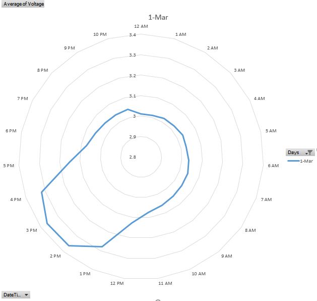
The code is given below. Please note I multiply my actual voltage with calibration variable. however during the high voltage time the calibration variable does not seem to work.
- Battery powers the soil sensor.
- The voltage regulator has been removed.
- MCU powered using vcc pin.
//#define MY_DEBUG #define MY_RF24_PA_LEVEL RF24_PA_LOW #define MY_BAUD_RATE 38400 #define MY_RADIO_NRF24 #define VIEW_READING #include <MySensors.h> #include <SPI.h> #include <math.h> #define round(x) ((x)>=0?(long)((x)+0.5):(long)((x)-0.5)) #define N_ELEMENTS(array) (sizeof(array)/sizeof((array)[0])) #define NUM_READS 10 #define CHILD_ID_MOISTURE 0 #define CHILD_ID_BATTERY 1 #define SLEEP_TIME 300000//10000 // Sleep time between reads (in milliseconds), was 10000 #define STABILIZATION_TIME 500 // Let the sensor stabilize before reading default BOD settings #define VOLTAGE_PIN A0 int index; long buffer[NUM_READS]; const long Known_Resistor = 4700; /// @brief Structure to be used in percentage and resistance values matrix to be filtered (have to be in pairs) typedef struct { int moisture; //!< Moisture long resistance; //!< Resistance } values; MyMessage soil_msg(CHILD_ID_MOISTURE, V_LEVEL); MyMessage voltage_msg(CHILD_ID_BATTERY, V_VOLTAGE); void presentation() { sendSketchInfo("Soil Moisture", "2.0"); present(CHILD_ID_MOISTURE, S_MOISTURE); present(CHILD_ID_BATTERY, S_MULTIMETER); } void setup() { pinMode(6, OUTPUT); pinMode(7, OUTPUT); digitalWrite(6, LOW); digitalWrite(7, LOW); } void loop() { //float dryLevel = readNoMoisture(); long moistureLevel = readAggSoilMoisture(); //float coeff = 100.00 / float(dryLevel); float voltage = readVoltage() * 1.57368; float batteryPcnt = voltage / 3.3 * 100; #ifdef VIEW_READING Serial.print("--Voltage:"); Serial.println(voltage); Serial.print("--Battery %:"); Serial.println(batteryPcnt); Serial.print("--Soil Sensor value:"); Serial.println(moistureLevel ); #endif send(soil_msg.set(moistureLevel, 1)); sendBatteryLevel(batteryPcnt); send(voltage_msg.set(voltage, 3), 1); sleep(SLEEP_TIME); } float readVoltage() { analogReference(INTERNAL); fakeRead(VOLTAGE_PIN); int sensorValue = analogRead(VOLTAGE_PIN); float voltage = sensorValue * 0.003363075; analogReference(DEFAULT); fakeRead(VOLTAGE_PIN); return voltage; } void fakeRead(int pin) { for (int counter = 0; counter < 5; counter++) { analogRead(pin); delay(STABILIZATION_TIME); } } // Averaging algorithm void addReading(long resistance) { buffer[index] = resistance; index++; if (index >= NUM_READS) { index = 0; } } long average() { long sum = 0; for (int i = 0; i < NUM_READS; i++) { sum += buffer[i]; } return (long)(sum / NUM_READS); } int readAggSoilMoisture() { measureRawSoilMoisture(6, 7, A1); long read1 = average(); measureRawSoilMoisture(7, 6, A2); long read2 = average(); long sensor1 = (read1 + read2) / 2; return int( ((sensor1 / (float)Known_Resistor) * 100.00)); } void measureRawSoilMoisture (int phase_b, int phase_a, int analog_input) { // read sensor, filter, and calculate resistance value // Noise filter: median filter for (int i = 0; i < NUM_READS; i++) { // Read 1 pair of voltage values digitalWrite(phase_a, HIGH); // set the voltage supply on delayMicroseconds(25); int supplyVoltage = analogRead(analog_input); // read the supply voltage delayMicroseconds(25); digitalWrite(phase_a, LOW); // set the voltage supply off delay(1); digitalWrite(phase_b, HIGH); // set the voltage supply on delayMicroseconds(25); int sensorVoltage = analogRead(analog_input); // read the sensor voltage delayMicroseconds(25); digitalWrite(phase_b, LOW); // set the voltage supply off // Calculate resistance // the 0.5 add-term is used to round to the nearest integer // Tip: no need to transform 0-1023 voltage value to 0-5 range, due to following fraction long resistance = abs(Known_Resistor * (supplyVoltage - sensorVoltage ) / sensorVoltage) ; delay(1); delay(STABILIZATION_TIME); addReading(resistance); } } -
Using voltage divider still might be necessary if you don't have battery directly connected to the MCU VCC, for example using step-up/down regulator to power the MCU. In this case you still can use a voltage divider and have a P+N Mosfet to control the current going through the voltage divider, so no leak to ground.
In practical terms you basically use another GPIO to enable or disable it the Mosfet when needed. I saw that on the Whisper Node board I'm using and seems to be effective (reference: https://bitbucket.org/talk2/whisper-node-avr#markdown-header-voltage-monitor)... In any case using high value resistors (over 100K) will reduce any current draw. Finally a small capacitor can be used to stabilize the voltage.
-
I have a DHT11 + NRF24L01 + Pro Mini 3.3v 8Mhz
All is working fine when on usb cable.. but it fails when connected to 2x 1.5 AA batteries..
what could be wrong ? -
I did a test with a variable power supply , and I can confirm that the pro mini does weird stuff at smaller then 3v, but it works at 3.3v.. I have now also ordered those 3.3v up-boosters (because I already bought the battery mounts) mentioned here.
-
What would be the best approach if I wanted a battery powered node using a 5V sensor? I want to build a secret knock sensor but I want it to be battery powered.
I was thinking about using 3xAA batteries (3x1.6 would be 4.8V max) and a 5V step-up converter and then power the sensor and the arduino (on the raw pin, since it's a 3.3V arduino). The radio would be powered from the VCC on the arduino.
-
Consider this option:
Use 2 AA batteries.
Change the BOD on the arduino to something lower than the 2.8V default.
Power everything from the batteries except the sensor.
Use the 5V step-up converter only for the sensor.@ileneken3 Good idea, i think I'll design it that way. I also had a closer look on eBay and found another sensor that runs on 3.3v.
-
"Disconnect or desolder the 3.3 VDC regulator because it is not needed." => Why it isn't needed? I assume it is needed when connecting a sensor that requires 3.3V (e.g. HTU21d or even the RFM69)? I assume the assumption made here is that you're using 2 AA 1.5V batteries? I'm using 3 LR44 (3x1.55V) so I suppose I still need the regulator.
MyController with USB powered WeMos D1/mini ESP8266 MQTT Gateways and battery powered Arduino Pro Mini using the RFM69 radio
-
"Disconnect or desolder the 3.3 VDC regulator because it is not needed." => Why it isn't needed? I assume it is needed when connecting a sensor that requires 3.3V (e.g. HTU21d or even the RFM69)? I assume the assumption made here is that you're using 2 AA 1.5V batteries? I'm using 3 LR44 (3x1.55V) so I suppose I still need the regulator.
-
Hi, i've got a barebones arduino circuit set up with a dht22 sensor. It's powered off 2 aa batteries. All works well with the two batteries even when they are running at about 3.0 volts combined (it would probably run at lower voltages but batteries haven't gone down that far yet). If i power directly from usb with my ftdi interface all works. However, when i add the 3.3v step up, the radio doesn't get a response from the nrf gateway anymore. I have a 4.7u capacitor on the nrf. The gateway is receiving some data but not all as i can see "mygateway1-out/0/255/0/0/18 2.1.1" in my mqtt broker every couple of seconds but the mysensors client never seems to get fully initialised. I've tried two or three of the step ups and checked the voltage with a multimeter and i'm getting circa 3.3v. One thing i did notice is that when i swapped in one of my 3 dht22's it worked initially but then stopped, the other two wouldn't (all work without the step up). I think this is a bit of a red herring but putting in here for information. Any thoughts?
-
share your schematic. from what you are describing it seems like the step up converter is not able to provide enough current.
-
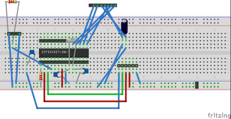
but the dht22 would not work, it requires at least 3.3v (however i succesuffly used it with 3V). I think that NRF has some decoupling capacitors onboard, so unless the boost converter design is not totaly wrong it shouldn't be a problem. schematic would be helpful.
-
but the dht22 would not work, it requires at least 3.3v (however i succesuffly used it with 3V). I think that NRF has some decoupling capacitors onboard, so unless the boost converter design is not totaly wrong it shouldn't be a problem. schematic would be helpful.
Here is my breadboard design, i'm afraid the schematic in fritzing isn't really in a state to post here. It's unreadable. The resistors shown in the diagram wouldn't have the correct values i used. The values i used are from the arduino site for creating an arduino. The ones shown are used for the sake of creating a pcb. The DHT22 goes on the 4 pin header, the NRF goes on the 8 pin header.