💬 Relay
-
Hi Everyone,
maybe the below will help people facing random incorrect behaviors.
In sample from december 2016 /mysensors/MySensors/examples/RelayActuator/RelayActuator.ino, there is something which could be seen as a bug.In my case, I have used that sample to control a lot of relais. I noticed some rare but really annoying errors. From time to time a relay got switched incorrectly.
Annoying and strange as coding was pretty straightforward. All relais are coded to act in pulse mode.digitalWrite(message.sensor-1+RELAY_1, RELAY_OFF); wait(1000); digitalWrite(message.sensor-1+RELAY_1, RELAY_ON);And this is the reason of the bug.
Explanation.
During that second of wait, a lot of things may occurs. Due to the 'message' declaration, it is possible that the 'message' is getting changed.
Typically a ping may come and as result the 'message' is not anymore the same.For that reason I would suggest the code to be changed a little bit.
void receive(const MyMessage &message_orig)
{
  MyMessage message;
  message = message_orig;
This way, the function works with a local copy and you are sure nothing can change during the processing.
Anyway, thanks for the sample it was nevertheless very helpful
-
@gohan This is not in the original coding. I needed something like a wait in order to make a relay pulse.
The wait increases the risk or the frequency of the trouble. Removing it does not solves the issue.
Processing of the function will always take time. And the message can still changes before reaching the end like it is show in the second trace. -
@gohan This is not in the original coding. I needed something like a wait in order to make a relay pulse.
The wait increases the risk or the frequency of the trouble. Removing it does not solves the issue.
Processing of the function will always take time. And the message can still changes before reaching the end like it is show in the second trace.You should treat the message like an ISR... get in and out so that you don't have another message colliding while you are in the function.
Get rid of that wait(). I couldn't find the source for that function but you could try to just use delay() to block while you hold the relay.
otherwise just set a flag to handle the relay event in loop() or use a Timer/callback like the MsTimer2 Library
example:
#include <MsTimer2.h> const byte onButton = 5; void setup() { Serial.begin(9600); pinMode(13, OUTPUT); pinMode(onButton, INPUT_PULLUP); } void loop() { if(onButtonPressed()) { flashLedThirteen(5000); } } bool onButtonPressed(void) { static unsigned long lastMillis = 0; static byte lastPress = HIGH; byte currentPress = digitalRead(onButton); if(currentPress != lastPress) { if(millis() - lastMillis < 200) return false; lastPress = currentPress; if(currentPress == LOW) { Serial.println(" button press detected!"); lastMillis = millis(); return true; } } return false; } void flashLedThirteen(int ledTime) { digitalWrite(13, HIGH); Serial.println("LED ON"); // sets a new timer callback function MsTimer2::set(ledTime, [] { // the square brackets define the start of the anonymous callback function which is executed after 5000 milliseconds in this example digitalWrite(13, LOW); Serial.println("Timer expired..."); Serial.println("LED OFF"); MsTimer2::stop(); }); // the curly brace defines the end of the anonymous callback function MsTimer2::start(); } -
You should treat the message like an ISR... get in and out so that you don't have another message colliding while you are in the function.
Get rid of that wait(). I couldn't find the source for that function but you could try to just use delay() to block while you hold the relay.
otherwise just set a flag to handle the relay event in loop() or use a Timer/callback like the MsTimer2 Library
example:
#include <MsTimer2.h> const byte onButton = 5; void setup() { Serial.begin(9600); pinMode(13, OUTPUT); pinMode(onButton, INPUT_PULLUP); } void loop() { if(onButtonPressed()) { flashLedThirteen(5000); } } bool onButtonPressed(void) { static unsigned long lastMillis = 0; static byte lastPress = HIGH; byte currentPress = digitalRead(onButton); if(currentPress != lastPress) { if(millis() - lastMillis < 200) return false; lastPress = currentPress; if(currentPress == LOW) { Serial.println(" button press detected!"); lastMillis = millis(); return true; } } return false; } void flashLedThirteen(int ledTime) { digitalWrite(13, HIGH); Serial.println("LED ON"); // sets a new timer callback function MsTimer2::set(ledTime, [] { // the square brackets define the start of the anonymous callback function which is executed after 5000 milliseconds in this example digitalWrite(13, LOW); Serial.println("Timer expired..."); Serial.println("LED OFF"); MsTimer2::stop(); }); // the curly brace defines the end of the anonymous callback function MsTimer2::start(); }@BulldogLowell said in 💬 Relay:
MsTimer2::
Thanks for the MSTimer, I was not aware of it.
And yes, definitively, having a wait() is probably the worst I could have written. Active wait cannot stay.
My intention, in the stuff I develop, was to remove it asap and probably by handling the wait time in the loop with flags.Maybe I was not clear enough about my intention when I opened this thread. I have no issue with what I develop. I already had several ways to solves this. And now, I have a new one with MSTimer. Again thanks.
I only wanted to raise the fact void receive(const MyMessage &message) may lead to trouble as 'message' content may change during processing of that function.
And if, like many, you are not skilled enough to code/debug.., you will face erratic issues and real difficulty to understand what is going wrong. -
@BulldogLowell said in 💬 Relay:
MsTimer2::
Thanks for the MSTimer, I was not aware of it.
And yes, definitively, having a wait() is probably the worst I could have written. Active wait cannot stay.
My intention, in the stuff I develop, was to remove it asap and probably by handling the wait time in the loop with flags.Maybe I was not clear enough about my intention when I opened this thread. I have no issue with what I develop. I already had several ways to solves this. And now, I have a new one with MSTimer. Again thanks.
I only wanted to raise the fact void receive(const MyMessage &message) may lead to trouble as 'message' content may change during processing of that function.
And if, like many, you are not skilled enough to code/debug.., you will face erratic issues and real difficulty to understand what is going wrong.I only wanted to raise the fact void receive(const MyMessage &message) may lead to trouble as 'message' content may change during processing of that function.
As I already explained... message cannot change during the function, because of constness.
The message handler is being called again from within itself (i.e. from wait()). You would then processing any new messages on that call. It looks as if the function may not be designed to perform recursively as you are trying to do in your code, so that would explain your unexpected/undefined results.
So yes, block during the relay's holding state or use another non-blocking method (i.e. flag or timer/callback) as you mentioned. Fully process each message before allowing the library to handle subsequent message calls.
;)
-
I only wanted to raise the fact void receive(const MyMessage &message) may lead to trouble as 'message' content may change during processing of that function.
As I already explained... message cannot change during the function, because of constness.
The message handler is being called again from within itself (i.e. from wait()). You would then processing any new messages on that call. It looks as if the function may not be designed to perform recursively as you are trying to do in your code, so that would explain your unexpected/undefined results.
So yes, block during the relay's holding state or use another non-blocking method (i.e. flag or timer/callback) as you mentioned. Fully process each message before allowing the library to handle subsequent message calls.
;)
I was looking for a solution for a low consumption relay and i was adviced in this thread to use a latching relay.
However since i just need to switch on or off a 12V Vcc (from Li ion battery) to trigger a solenoid valve, i'm wondering whether i need a relay for that :
looking at the schematic from post #2 in https://forum.arduino.cc/index.php?topic=436555.0 may be i coud just have my solenoid valve directly in place of the relay in the schematic. In other words , i just need a transistor and not a real relay ... just because my application is a low voltage (12V to apply directly to the Vcc in the schematic) rather than 230V one: can someone confirm ? There is a diode in the schematic : what is it needed for ?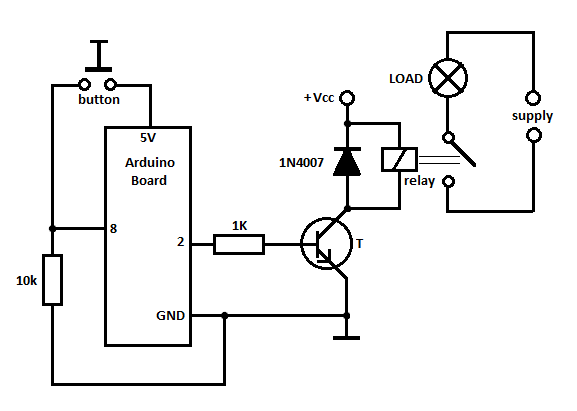
-
I was looking for a solution for a low consumption relay and i was adviced in this thread to use a latching relay.
However since i just need to switch on or off a 12V Vcc (from Li ion battery) to trigger a solenoid valve, i'm wondering whether i need a relay for that :
looking at the schematic from post #2 in https://forum.arduino.cc/index.php?topic=436555.0 may be i coud just have my solenoid valve directly in place of the relay in the schematic. In other words , i just need a transistor and not a real relay ... just because my application is a low voltage (12V to apply directly to the Vcc in the schematic) rather than 230V one: can someone confirm ? There is a diode in the schematic : what is it needed for ?Since an inductor (im many cases a relay coil) cannot change it's current instantly, the flyback diode provides a path for the current when the coil is switched off. Otherwise, a voltage spike will occur causing arcing on switch contacts or possibly destroying switching transistors.
-
treat yor solenoid as it was a relay, the difference is that relay switches flow of current, and solenoid valve switches flow of water. so You have to use the same schematic, but put your valve where the relay is. But if You want power it from a battery, choose a latching solenoid valve instead of regular solenoid valve - and that requeires different schematic.
@rozpruwacz
thanks, but do you mean that the schematic simply would not work for the regular valve or that it would work but not be low power cinsumption design anymore ?
I have a regular solenoid valve but in my application the valve is normally closed and it will be only exceptionnally opened and for a short time when the 12V is applied, so i guess that i can live with it ...
As for the transistor in the schematic, except it seems to be a NPN , i don't know if i need a particular one for it . probably i can just buy a 2N3904 , or is there a better choice? -
the schematic you posted is not using latching relay/valve. it doesn't matter if it is relay or valve. both works the same and consume power when in ON state. If you plan to use it in a way that the valve will be ON for very short periods than it is not important if it is latching or not.
when choosing a transistor for such use, You have to look at its datasheet into "absolute maximum ratings" section and check if it will handle the voltages you will apply to it. 2N3904 looks like it will handle 12V without a problem.
-
the schematic you posted is not using latching relay/valve. it doesn't matter if it is relay or valve. both works the same and consume power when in ON state. If you plan to use it in a way that the valve will be ON for very short periods than it is not important if it is latching or not.
when choosing a transistor for such use, You have to look at its datasheet into "absolute maximum ratings" section and check if it will handle the voltages you will apply to it. 2N3904 looks like it will handle 12V without a problem.
@rozpruwacz
thanks , i will use 2N2222 because the valve needs between 200 and 400 mA.
I'v read the 2N3904 is OK for < 100 mA -
It works very well with the transistor and schematic posted above. I think the valve is a latching valve because it only discharges the battery when there is a transition. The only remaining problem is that the 5V arduino alone is too much power consuming. So i'm wondering if the transistor could as well work with a 3.3V arduino, that is when the signal level on the transistor Base is 3.3V rather than 5 V ... then i also could remove the arduino led but i'll need to keep the arduino regulator because my 3.7V cell voltage is too much greater than 3.3V
-
It works very well with the transistor and schematic posted above. I think the valve is a latching valve because it only discharges the battery when there is a transition. The only remaining problem is that the 5V arduino alone is too much power consuming. So i'm wondering if the transistor could as well work with a 3.3V arduino, that is when the signal level on the transistor Base is 3.3V rather than 5 V ... then i also could remove the arduino led but i'll need to keep the arduino regulator because my 3.7V cell voltage is too much greater than 3.3V
@fhenryco Actually the internal resistor of the solenoid is 27 Ohm while the resistance between C and E of the transistor in the passing state is 35 Ohm ... so it remains less than Vcc/2 for my solenoid which needs 12V ... so i need to tune my boost module at the max ==> more than 30V ... that does not seem ideal, may be i shoud choose another transistor with less internal resistor, but i have little experience with transistors : studied them a long time ago , so if someone can suggest something smart, ready to buy it ...
-
Can I suggest a change to this page?
As it stands the wiring diagram only applies to sketch 1 (without switch). It could get confusing as the 2 sketches use different pins for the relay and there is no need for this.
I propose that the wiring diagram be changed for the relay to be attached to pin 4.
The first sketch needs the relay pin to change from pin 3 to pin 4.That's it. Then the diagram and sketches will work whichever way the builder wants to do it.
-
-
@mfalkvidd when updating the example sketch you could maybe consider my version of the relay sketch which offers some nice additions: https://forum.mysensors.org/topic/6638/multiple-relays-motion-sketch-fully-customizable-optional-timer-manual-override
-
@mfalkvidd when updating the example sketch you could maybe consider my version of the relay sketch which offers some nice additions: https://forum.mysensors.org/topic/6638/multiple-relays-motion-sketch-fully-customizable-optional-timer-manual-override
@HenryWhite my mind is divided when it comes to that type of sketch. Yes, it has a lot of functionality. Yes, it is probably what people need anyway. But the examples are meant to be used by someone who is just getting into diy home automation. Someone new should be able to understand as much of the sketch as possible. There should be as little as possible to trubleshoot. If the sketch is complex, most people's initial reaction will be that there is something wrong with the code, when in reality almost all newbie problems are power or wiring-related. Keeping the sketch simple helps, at lest a bit.