Skip to content
  • MySensors
  • OpenHardware.io
  • Categories
  • Recent
  • Tags
  • Popular
Skins
  • Light
  • Brite
  • Cerulean
  • Cosmo
  • Flatly
  • Journal
  • Litera
  • Lumen
  • Lux
  • Materia
  • Minty
  • Morph
  • Pulse
  • Sandstone
  • Simplex
  • Sketchy
  • Spacelab
  • United
  • Yeti
  • Zephyr
  • Dark
  • Cyborg
  • Darkly
  • Quartz
  • Slate
  • Solar
  • Superhero
  • Vapor

  • Default (No Skin)
  • No Skin
Collapse
Brand Logo
  1. Home
  2. OpenHardware.io
  3. 💬 Ikea Molgan Hack

💬 Ikea Molgan Hack

Scheduled Pinned Locked Moved OpenHardware.io
motionmolganhackpirmysensorsikea
90 Posts 16 Posters 27.4k Views 15 Watching
  • Oldest to Newest
  • Newest to Oldest
  • Most Votes
Reply
  • Reply as topic
Log in to reply
This topic has been deleted. Only users with topic management privileges can see it.
  • GertSandersG Offline
    GertSandersG Offline
    GertSanders
    Hardware Contributor
    wrote on last edited by
    #14

    This one made it on the Adafruit blog:

    https://blog.adafruit.com/2016/11/30/add-nrf2401-arduino-functionality-to-hacked-ikea-molgan-led-lamp-ikeausa/

    Great Success Yveaux !!!

    YveauxY 1 Reply Last reply
    1
    • GertSandersG GertSanders

      This one made it on the Adafruit blog:

      https://blog.adafruit.com/2016/11/30/add-nrf2401-arduino-functionality-to-hacked-ikea-molgan-led-lamp-ikeausa/

      Great Success Yveaux !!!

      YveauxY Offline
      YveauxY Offline
      Yveaux
      Mod
      wrote on last edited by
      #15

      @GertSanders Awesome! Thanks for the tip man!

      http://yveaux.blogspot.nl

      S 1 Reply Last reply
      0
      • L Offline
        L Offline
        LastSamurai
        Hardware Contributor
        wrote on last edited by
        #16

        I finished my first hacked molgan 2 days ago and it's detecting motion really well (and looks so much better than my custom builds).
        So overall I love it but it also seems to have one problem: batteries...

        I started it about 48h ago and the first reading was 2.119V but within some hours it dropped to 2.072V, though today it climbed back up to 2.096V. Thats still 23mV in ~2 days though.
        Is this just the discharge curve and some imprecise readings? @Yveaux Whats the consumption of your modules?

        YveauxY 1 Reply Last reply
        0
        • L LastSamurai

          I finished my first hacked molgan 2 days ago and it's detecting motion really well (and looks so much better than my custom builds).
          So overall I love it but it also seems to have one problem: batteries...

          I started it about 48h ago and the first reading was 2.119V but within some hours it dropped to 2.072V, though today it climbed back up to 2.096V. Thats still 23mV in ~2 days though.
          Is this just the discharge curve and some imprecise readings? @Yveaux Whats the consumption of your modules?

          YveauxY Offline
          YveauxY Offline
          Yveaux
          Mod
          wrote on last edited by
          #17

          @LastSamurai I don't have the exact figures at hand, but I had a look at the reported battery consumption of one of them. It dropped from 81% in August to 70% today.
          I'd just let it run for a while and see how it goes.

          http://yveaux.blogspot.nl

          1 Reply Last reply
          1
          • L Offline
            L Offline
            LastSamurai
            Hardware Contributor
            wrote on last edited by
            #18

            So yesterday my molgan started to constantly trigger, which I think might indicate that the voltage is too low. It has dropped down to 1950mV. I will try it with new batteries later today, but the power consumption still seems to be way too high compared to yours @Yveaux.
            I have removed R17 to disable all leds and I have changed the fuses and used your sketch. Any idea what might have gone wrong?

            YveauxY 1 Reply Last reply
            0
            • L LastSamurai

              So yesterday my molgan started to constantly trigger, which I think might indicate that the voltage is too low. It has dropped down to 1950mV. I will try it with new batteries later today, but the power consumption still seems to be way too high compared to yours @Yveaux.
              I have removed R17 to disable all leds and I have changed the fuses and used your sketch. Any idea what might have gone wrong?

              YveauxY Offline
              YveauxY Offline
              Yveaux
              Mod
              wrote on last edited by
              #19

              @LastSamurai can you measure the consumption of individual parts? E.g. The Molgan hardware, the arduino and the radio?

              http://yveaux.blogspot.nl

              L 1 Reply Last reply
              0
              • YveauxY Yveaux

                @LastSamurai can you measure the consumption of individual parts? E.g. The Molgan hardware, the arduino and the radio?

                L Offline
                L Offline
                LastSamurai
                Hardware Contributor
                wrote on last edited by
                #20

                @Yveaux Ok I will try to do that. I did try other (new) batteries though and got the same values (about 2V strangely). Then it started to continuously trigger. I described the problem here.
                It's so frustrating, but something seems to be wrong with my whole network I guess....

                YveauxY 1 Reply Last reply
                0
                • L LastSamurai

                  @Yveaux Ok I will try to do that. I did try other (new) batteries though and got the same values (about 2V strangely). Then it started to continuously trigger. I described the problem here.
                  It's so frustrating, but something seems to be wrong with my whole network I guess....

                  YveauxY Offline
                  YveauxY Offline
                  Yveaux
                  Mod
                  wrote on last edited by
                  #21

                  @LastSamurai how did you measure 2V? Measured with a DMM 2XAAA fresh alkaline batteries should be more in the 3V range. This makes a big difference, as at around 2V the Pir starts to behave weird, as you already experienced.

                  http://yveaux.blogspot.nl

                  L 1 Reply Last reply
                  0
                  • YveauxY Yveaux

                    @LastSamurai how did you measure 2V? Measured with a DMM 2XAAA fresh alkaline batteries should be more in the 3V range. This makes a big difference, as at around 2V the Pir starts to behave weird, as you already experienced.

                    L Offline
                    L Offline
                    LastSamurai
                    Hardware Contributor
                    wrote on last edited by
                    #22

                    @Yveaux I used the vcc library to let the atmega328 measure the voltage and send it as a sensor value to my controller. I guess I will have to investigate that too. Measuring the batteries outside the case with a multimeter I got 1.5V for each one (without any load though).

                    1 Reply Last reply
                    0
                    • L Offline
                      L Offline
                      LastSamurai
                      Hardware Contributor
                      wrote on last edited by LastSamurai
                      #23

                      PS I just measured with the multimeter and the measurements are strange. The board voltage is at about 2.9V (so more like expected) and reaches the atmega as well as the NRF. Overall voltage is at about 4.8V.
                      The trigger pad seems to be constantly high though (~2.7V) and the node doesn't seem to show up at the gateway anymore. I guess some serial debugging is needed now. Perhaps some component has died... falsy NRF modules would perhaps explain the errors with my nodes :(

                      PPS now the sensor is sending again (strange). The trigger pad is still constantly high though. I guess I will have to desolder the pcb again to have a look at the PIR pcb. Perhaps somethings wrong there...

                      1 Reply Last reply
                      0
                      • L Offline
                        L Offline
                        LastSamurai
                        Hardware Contributor
                        wrote on last edited by
                        #24

                        So I took some measurements and and the molgan pcb on its own works just fine. The mysensors pcb with a stable 3.3V power source worked too. When I wanted to measure the power consumption I realized that a fuse in my multimeter was defect... so I am still waiting for a replacement. Will post an update once its here.

                        1 Reply Last reply
                        0
                        • L Offline
                          L Offline
                          LastSamurai
                          Hardware Contributor
                          wrote on last edited by
                          #25

                          Sorry for the spam here but I have the fuse now and have just been measuring the pcbs.

                          • Molgan PIR pcb: 17mA triggered, 7mA otherwise
                          • mysensors PCB: 18mA sending, 6uA sleeping

                          The second one looks fine to me but the molgan pcb draws way to much power for battery usage, right?! @Yveaux did you measure the power consumption of yours? I just realized that I did not change the resistor that controls the trigger time. I thought 30s are fine but that makes it draw more power too...

                          I will also start to test with the second molgan I bought. Really want this to work ;)

                          YveauxY 1 Reply Last reply
                          0
                          • L LastSamurai

                            Sorry for the spam here but I have the fuse now and have just been measuring the pcbs.

                            • Molgan PIR pcb: 17mA triggered, 7mA otherwise
                            • mysensors PCB: 18mA sending, 6uA sleeping

                            The second one looks fine to me but the molgan pcb draws way to much power for battery usage, right?! @Yveaux did you measure the power consumption of yours? I just realized that I did not change the resistor that controls the trigger time. I thought 30s are fine but that makes it draw more power too...

                            I will also start to test with the second molgan I bought. Really want this to work ;)

                            YveauxY Offline
                            YveauxY Offline
                            Yveaux
                            Mod
                            wrote on last edited by
                            #26

                            @LastSamurai said in 💬 Ikea Molgan Hack:

                            Sorry for the spam here but I have the fuse now and have just been measuring the pcbs.

                            No worries, that's what this thread is for, right? ;-)

                            The second one looks fine to me but the molgan pcb draws way to much power for battery usage, right?! @Yveaux did you measure the power consumption of yours?

                            I did measure it (when I found out the power usage was less with the regulator, than without) but I can't seem to find the results anymore...
                            @dynamite mentioned in this thread "The powerconsumption of the PIR when not triggered is approx. 60 uA and when triggered 160 uA.".

                            I just realized that I did not change the resistor that controls the trigger time. I thought 30s are fine but that makes it draw more power too...

                            Only marginally I guess, unless it triggers all the time.

                            I will also start to test with the second molgan I bought. Really want this to work ;)

                            Please do so, at least for comparison.

                            http://yveaux.blogspot.nl

                            1 Reply Last reply
                            0
                            • L Offline
                              L Offline
                              LastSamurai
                              Hardware Contributor
                              wrote on last edited by
                              #27

                              I measured with the new molgan and got nearly the same results. Perhaps my cheap multimeter isn't accurate enough though.
                              I moved the mysensor pcb to the new molgan pcb and tried this out. Strange result: at first it only send the initial messages but no triggers. After some minutes the opposite happened: it started to randomly trigger (or at least send them). Then after some more time the random triggers stopped and now its working as intended.
                              Perhaps it just the setup time of the PIR or the warmer air coming from a heater nearby... I will keep an eye on it the next days.

                              1 Reply Last reply
                              0
                              • L Offline
                                L Offline
                                LastSamurai
                                Hardware Contributor
                                wrote on last edited by
                                #28

                                Ok I did some more testing and the error seems to be pretty random. Sometimes the PIR works as intended for some time, sometimes it just keeps triggering constantly. I am pretty sure sleeping/waking up or sending the message is somehow influencing the PIR (don't know what else it could be).
                                Does anyone have an idea how to fix this (some wait() code or some cap somewhere perhaps)?

                                1 Reply Last reply
                                0
                                • scalzS Offline
                                  scalzS Offline
                                  scalz
                                  Hardware Contributor
                                  wrote on last edited by scalz
                                  #29

                                  i've not looked at the molgan..but for fixing this:

                                  • if capa to place, that would be directly to the PIR sensor VCC pin (100uf), ideally close to it.
                                  • or by software : ignoring false triggers, or disable the irq when it's not needed, or slow down a little bit clock during these false trigger.
                                  1 Reply Last reply
                                  1
                                  • gohanG Offline
                                    gohanG Offline
                                    gohan
                                    Mod
                                    wrote on last edited by gohan
                                    #30

                                    Agreed on the capacitor on the vcc, I had some random triggers on a pir sensor and they were gone when I added a cap to the 5v pin

                                    1 Reply Last reply
                                    1
                                    • L Offline
                                      L Offline
                                      LastSamurai
                                      Hardware Contributor
                                      wrote on last edited by
                                      #31

                                      @scalz and @gohan thank you very much! I added a 47uF electrolytic cap which helped a little. Afterwards I also added another 22nF ceramic cap. After that it seems to working just fine (for about 2 days now).
                                      @Yveaux perhaps you could create a new version including some caps to fix this problem for anyone? I am still glad to finally be able to use this good looking cheap sensor. Thanks again for your work

                                      YveauxY 1 Reply Last reply
                                      0
                                      • L LastSamurai

                                        @scalz and @gohan thank you very much! I added a 47uF electrolytic cap which helped a little. Afterwards I also added another 22nF ceramic cap. After that it seems to working just fine (for about 2 days now).
                                        @Yveaux perhaps you could create a new version including some caps to fix this problem for anyone? I am still glad to finally be able to use this good looking cheap sensor. Thanks again for your work

                                        YveauxY Offline
                                        YveauxY Offline
                                        Yveaux
                                        Mod
                                        wrote on last edited by
                                        #32

                                        @LastSamurai Great to hear it runs stable so far!
                                        As I understood the capacitor is placed on the Molgan PCB, and that's a PCB I cannot redesign...
                                        Where execactly did you plave the capacitor? Could you post a picture, so I can add it as a hint to the build guide.

                                        http://yveaux.blogspot.nl

                                        1 Reply Last reply
                                        0
                                        • L Offline
                                          L Offline
                                          LastSamurai
                                          Hardware Contributor
                                          wrote on last edited by
                                          #33

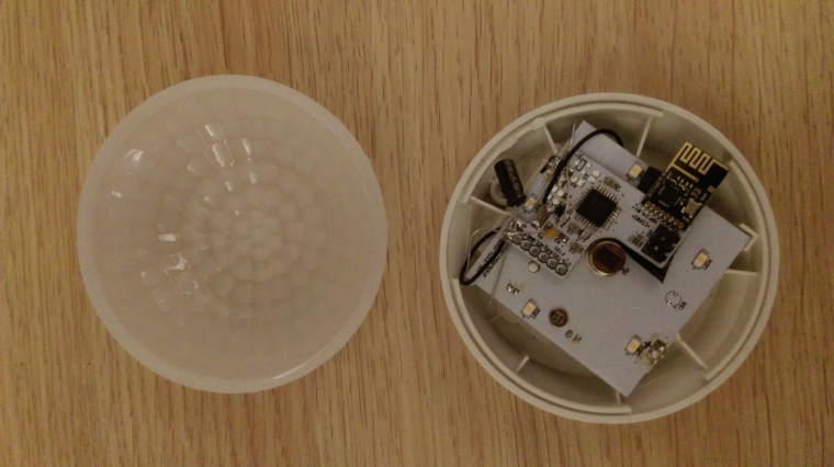
                                          As the Molgan PCB works fine without the addon PCB it has to be its "fault" so I guess it makes sense to add them there. I placed the caps between GND and VCC of your pcb (which is linked to the molgan pcb). I also noticed that your pcb doesn't have any caps at the radio (right?). Normally you would add a 47uF caps there. Might that be part of the problem?

                                          Here is a quick picture. I can take a better one later.
                                          0_1488219882399_caps.jpg

                                          YveauxY 1 Reply Last reply
                                          0
                                          Reply
                                          • Reply as topic
                                          Log in to reply
                                          • Oldest to Newest
                                          • Newest to Oldest
                                          • Most Votes


                                          18

                                          Online

                                          11.7k

                                          Users

                                          11.2k

                                          Topics

                                          113.1k

                                          Posts


                                          Copyright 2025 TBD   |   Forum Guidelines   |   Privacy Policy   |   Terms of Service
                                          • Login

                                          • Don't have an account? Register

                                          • Login or register to search.
                                          • First post
                                            Last post
                                          0
                                          • MySensors
                                          • OpenHardware.io
                                          • Categories
                                          • Recent
                                          • Tags
                                          • Popular