Skip to content
  • MySensors
  • OpenHardware.io
  • Categories
  • Recent
  • Tags
  • Popular
Skins
  • Light
  • Brite
  • Cerulean
  • Cosmo
  • Flatly
  • Journal
  • Litera
  • Lumen
  • Lux
  • Materia
  • Minty
  • Morph
  • Pulse
  • Sandstone
  • Simplex
  • Sketchy
  • Spacelab
  • United
  • Yeti
  • Zephyr
  • Dark
  • Cyborg
  • Darkly
  • Quartz
  • Slate
  • Solar
  • Superhero
  • Vapor

  • Default (No Skin)
  • No Skin
Collapse
Brand Logo
  1. Home
  2. My Project
  3. Powering mote 24/7 using only a supercap and solar

Powering mote 24/7 using only a supercap and solar

Scheduled Pinned Locked Moved My Project
239 Posts 10 Posters 122.5k Views 14 Watching
  • Oldest to Newest
  • Newest to Oldest
  • Most Votes
Reply
  • Reply as topic
Log in to reply
This topic has been deleted. Only users with topic management privileges can see it.
  • S Offline
    S Offline
    scalz
    Hardware Contributor
    wrote on last edited by scalz
    #37

    @NeverDie
    oh, no competition... or let me win please :laughing: I'm joking. that said i'm not sure, but I think i see Wally on your board ;)
    I'm back in an hour for sharing. i need to assemble few boards for myself :)

    N 1 Reply Last reply
    0
    • S scalz

      @NeverDie
      oh, no competition... or let me win please :laughing: I'm joking. that said i'm not sure, but I think i see Wally on your board ;)
      I'm back in an hour for sharing. i need to assemble few boards for myself :)

      N Offline
      N Offline
      NeverDie
      Hero Member
      wrote on last edited by NeverDie
      #38

      @scalz said:

      i'm not sure, but I think i see Wally on your board ;)

      LOL. You probably need better ventilation when you're soldering. The fumes are getting to you. :laughing:

      N S 2 Replies Last reply
      0
      • N NeverDie

        @scalz said:

        i'm not sure, but I think i see Wally on your board ;)

        LOL. You probably need better ventilation when you're soldering. The fumes are getting to you. :laughing:

        N Offline
        N Offline
        NeverDie
        Hero Member
        wrote on last edited by NeverDie
        #39

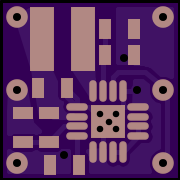
        Interestingly, in today's mail I received the "BQ25504 Stripped" PCB
        alt text
        https://oshpark.com/shared_projects/CYdxpE9S

        that I ordered on November 16. That's about twice faster than their normal turnaround speed when I send them new fab files. The board itself is noticeably smaller than the Tindie board.

        1 Reply Last reply
        0
        • N NeverDie

          @scalz said:

          i'm not sure, but I think i see Wally on your board ;)

          LOL. You probably need better ventilation when you're soldering. The fumes are getting to you. :laughing:

          S Offline
          S Offline
          scalz
          Hardware Contributor
          wrote on last edited by scalz
          #40

          @NeverDie said:

          @scalz said:

          i'm not sure, but I think i see Wally on your board ;)

          LOL. You probably need better ventilation when you're soldering. The fumes are getting to you. :laughing:

          :laughing: no fumes tonight, reflow oven working for me :)

          Wally is in your GND pour, in each of your board I think.
          I mean you should not have any gnd around some settings resistors and capa.
          Check carefully the section 11.1 Layout Guidelines in datasheet.
          This is why on the reference layout you see Top GND only on half board. Or then it may happen less performance depending of mutliple factors.
          It's also explained how to route the GND.

          That said, in case it can help, here is my gerbers https://www.dropbox.com/s/tugdbc3cfrlmdu7/bq25504_gerbers.rar?dl=0

          Enjoy

          N 1 Reply Last reply
          0
          • S scalz

            @NeverDie said:

            @scalz said:

            i'm not sure, but I think i see Wally on your board ;)

            LOL. You probably need better ventilation when you're soldering. The fumes are getting to you. :laughing:

            :laughing: no fumes tonight, reflow oven working for me :)

            Wally is in your GND pour, in each of your board I think.
            I mean you should not have any gnd around some settings resistors and capa.
            Check carefully the section 11.1 Layout Guidelines in datasheet.
            This is why on the reference layout you see Top GND only on half board. Or then it may happen less performance depending of mutliple factors.
            It's also explained how to route the GND.

            That said, in case it can help, here is my gerbers https://www.dropbox.com/s/tugdbc3cfrlmdu7/bq25504_gerbers.rar?dl=0

            Enjoy

            N Offline
            N Offline
            NeverDie
            Hero Member
            wrote on last edited by NeverDie
            #41

            @scalz

            What is "Wally"? I haven't heard that term before, and it's not in the datasheet either. I thought you were jokingly making an obscure reference to Waldo, as in "Where's Waldo?" That's why I had thought the fumes must have gotten to you. I realize now that Wally must instead be a French electrical term of some kind.

            1 Reply Last reply
            0
            • S Offline
              S Offline
              scalz
              Hardware Contributor
              wrote on last edited by
              #42

              @NeverDie
              lol
              yep you were right, where's waldo/wally but where i live we say Charlie :)

              N 1 Reply Last reply
              0
              • S scalz

                @NeverDie
                lol
                yep you were right, where's waldo/wally but where i live we say Charlie :)

                N Offline
                N Offline
                NeverDie
                Hero Member
                wrote on last edited by NeverDie
                #43

                @scalz
                Sacrébleu. I just now tried sending your gerber files to OSH PARK, but it complains, " I can't find a board outline file." A fab will need a complete set of files to get anything done.

                1 Reply Last reply
                0
                • N Offline
                  N Offline
                  NeverDie
                  Hero Member
                  wrote on last edited by
                  #44

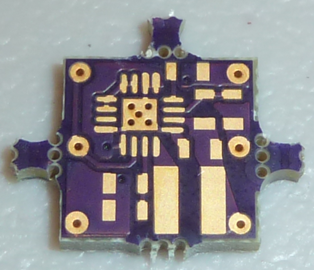
                  In any event, the "stripped" BQ25504 board that I received yesterday looks rather disheveled:
                  0_1479991946287_BQ25504_disheveled.jpg

                  @scalz
                  Do you see any Wally's in it?

                  1 Reply Last reply
                  0
                  • S Offline
                    S Offline
                    scalz
                    Hardware Contributor
                    wrote on last edited by scalz
                    #45

                    @NeverDie
                    ahah :)

                    If it can help you, here it is : https://oshpark.com/shared_projects/XRsFBtzu
                    This is because i've generated the gerbers with an other fabhouse CAM.
                    In mine, GML is the dimension layer if i remember right.
                    You can also open the gerbers in a viewer like Gerbv etc..
                    For oshpark, i have modified it a little bit because of slightly different DRC.

                    N 1 Reply Last reply
                    0
                    • S scalz

                      @NeverDie
                      ahah :)

                      If it can help you, here it is : https://oshpark.com/shared_projects/XRsFBtzu
                      This is because i've generated the gerbers with an other fabhouse CAM.
                      In mine, GML is the dimension layer if i remember right.
                      You can also open the gerbers in a viewer like Gerbv etc..
                      For oshpark, i have modified it a little bit because of slightly different DRC.

                      N Offline
                      N Offline
                      NeverDie
                      Hero Member
                      wrote on last edited by
                      #46

                      @scalz
                      Thanks. I just now ordered it.

                      Interestingly, if you look at Ti's eval board for the bq25504, they do in fact connect the top and bottom ground planes, and the thermal pad on the BQ25504 is connected to the entire bottom ground plane, not just another small thermal pad:

                      https://www.ti.com/seclit/df/tidu094/tidu094.pdf

                      1 Reply Last reply
                      0
                      • S Offline
                        S Offline
                        scalz
                        Hardware Contributor
                        wrote on last edited by
                        #47

                        @NeverDie
                        cool.
                        Well, perhaps it's ok. I followed datasheet guidelines..no matter the powerpad is connected on top.

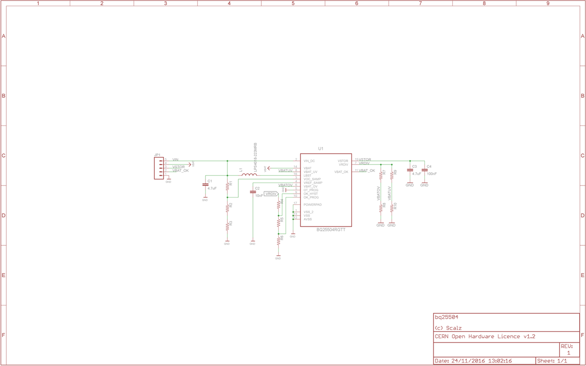
                        Perhaps, you may need the schematic to know where parts are placed ;)
                        0_1479989388027_sch.png
                        You'll need to set your resistors of course.

                        If really needed, no problem i can upload all the files..

                        N 2 Replies Last reply
                        0
                        • S scalz

                          @NeverDie
                          cool.
                          Well, perhaps it's ok. I followed datasheet guidelines..no matter the powerpad is connected on top.

                          Perhaps, you may need the schematic to know where parts are placed ;)
                          0_1479989388027_sch.png
                          You'll need to set your resistors of course.

                          If really needed, no problem i can upload all the files..

                          N Offline
                          N Offline
                          NeverDie
                          Hero Member
                          wrote on last edited by
                          #48

                          @scalz

                          You should upload it to https://www.openhardware.io/ I'm sure a lot of people would find it very helpful.

                          1 Reply Last reply
                          0
                          • S scalz

                            @NeverDie
                            cool.
                            Well, perhaps it's ok. I followed datasheet guidelines..no matter the powerpad is connected on top.

                            Perhaps, you may need the schematic to know where parts are placed ;)
                            0_1479989388027_sch.png
                            You'll need to set your resistors of course.

                            If really needed, no problem i can upload all the files..

                            N Offline
                            N Offline
                            NeverDie
                            Hero Member
                            wrote on last edited by
                            #49

                            @scalz
                            Out of curiosity, why did you choose such a large inductor? I notice that the "stripped" BQ25504 pcb (photo above) did the same thing. Are there advantages to the larger size?

                            N 1 Reply Last reply
                            0
                            • N NeverDie

                              @scalz
                              Out of curiosity, why did you choose such a large inductor? I notice that the "stripped" BQ25504 pcb (photo above) did the same thing. Are there advantages to the larger size?

                              N Offline
                              N Offline
                              NeverDie
                              Hero Member
                              wrote on last edited by NeverDie
                              #50

                              @NeverDie said:

                              @scalz
                              Out of curiosity, why did you choose such a large inductor? I notice that the "stripped" BQ25504 pcb (photo above) did the same thing. Are there advantages to the larger size?

                              Nevermind. I see now from your schematic that you're using the coilcraft inductor from Table 1 of the DS.

                              1 Reply Last reply
                              0
                              • N Offline
                                N Offline
                                NeverDie
                                Hero Member
                                wrote on last edited by
                                #51

                                Interestingly, looking at the Tindie board now, it's clear based on its inductor's dimensions that the Tindie board is not using one of the Table 1 recommended inductors. Perhaps that explains why the Tindie board appears to be sucking wind at the lower voltages.

                                N 1 Reply Last reply
                                0
                                • N NeverDie

                                  Interestingly, looking at the Tindie board now, it's clear based on its inductor's dimensions that the Tindie board is not using one of the Table 1 recommended inductors. Perhaps that explains why the Tindie board appears to be sucking wind at the lower voltages.

                                  N Offline
                                  N Offline
                                  NeverDie
                                  Hero Member
                                  wrote on last edited by NeverDie
                                  #52

                                  @NeverDie
                                  Coilcraft doesn't seem very available in the US, but Wurth has a similar one that's still on the DS table list that's probably a good substitute: http://www.digikey.com/product-detail/en/wurth-electronics-inc/744031220/732-1012-1-ND/1639073

                                  Also, I'll have to update my board to use a larger inductor. I had blithely assumed, based on the Tindie board, that an 0805 would be sufficient, but now that I'm digging into it probably not.

                                  N 1 Reply Last reply
                                  0
                                  • N NeverDie

                                    @NeverDie
                                    Coilcraft doesn't seem very available in the US, but Wurth has a similar one that's still on the DS table list that's probably a good substitute: http://www.digikey.com/product-detail/en/wurth-electronics-inc/744031220/732-1012-1-ND/1639073

                                    Also, I'll have to update my board to use a larger inductor. I had blithely assumed, based on the Tindie board, that an 0805 would be sufficient, but now that I'm digging into it probably not.

                                    N Offline
                                    N Offline
                                    NeverDie
                                    Hero Member
                                    wrote on last edited by
                                    #53

                                    @NeverDie
                                    I take it back. The Wurth component I just referenced has a rather complex looking land pattern.

                                    Fortunately, the last remaining component on the Table 1 recommended list is a Wurth that has a much easier land pattern: http://www.digikey.com/product-detail/en/wurth-electronics-inc/744025220/732-2619-1-ND/2445718

                                    1 Reply Last reply
                                    0
                                    • S Offline
                                      S Offline
                                      scalz
                                      Hardware Contributor
                                      wrote on last edited by scalz
                                      #54

                                      @NeverDie
                                      yep from guidelines.
                                      but also because it's better to use shielded inductors for multiple reasons like EMI..and also good inductors and parts give better perf, efficiency etc.. lot of docs on this.

                                      That said, the footprint i use is also compatible with the 0805 advised in datasheet if i remember. it's possible to use both ref for the same footprint i've not the datasheet in front of me right now but width shoud be ok.

                                      N 1 Reply Last reply
                                      0
                                      • S scalz

                                        @NeverDie
                                        yep from guidelines.
                                        but also because it's better to use shielded inductors for multiple reasons like EMI..and also good inductors and parts give better perf, efficiency etc.. lot of docs on this.

                                        That said, the footprint i use is also compatible with the 0805 advised in datasheet if i remember. it's possible to use both ref for the same footprint i've not the datasheet in front of me right now but width shoud be ok.

                                        N Offline
                                        N Offline
                                        NeverDie
                                        Hero Member
                                        wrote on last edited by
                                        #55

                                        It seems as though TI's evaluation board ignores the design recommendations given in the datasheet, in particular: "...it is highly recommended that no ground planes be poured near the voltage setting resistors or the sample and hold capacitor." In the case of the TI's evaluation board, virtually the entire bottom layer is a ground plane. I don't know what to make of that.

                                        Anyhow, I ordered the Wurth inductors. I also ordered a 3x3 QFN-16 solder stencil as some fallback insurance, as the BQ25504 looks like it will be very challenging to solder.

                                        1 Reply Last reply
                                        0
                                        • N Offline
                                          N Offline
                                          NeverDie
                                          Hero Member
                                          wrote on last edited by
                                          #56

                                          Also, the layout guidelines say, " It is best to use vias and bottom traces for connecting the inductor to its respective pins instead of the capacitors." Yet, the recommended layout doesn't do that.
                                          N 1 Reply Last reply
                                          0

                                          Hello! It looks like you're interested in this conversation, but you don't have an account yet.

                                          Getting fed up of having to scroll through the same posts each visit? When you register for an account, you'll always come back to exactly where you were before, and choose to be notified of new replies (either via email, or push notification). You'll also be able to save bookmarks and upvote posts to show your appreciation to other community members.

                                          With your input, this post could be even better 💗

                                          Register Login
                                          Reply
                                          • Reply as topic
                                          Log in to reply
                                          • Oldest to Newest
                                          • Newest to Oldest
                                          • Most Votes


                                          8

                                          Online

                                          12.0k

                                          Users

                                          11.2k

                                          Topics

                                          113.4k

                                          Posts


                                          Copyright 2025 TBD   |   Forum Guidelines   |   Privacy Policy   |   Terms of Service
                                          • Login

                                          • Don't have an account? Register

                                          • Login or register to search.
                                          • First post
                                            Last post
                                          0
                                          • MySensors
                                          • OpenHardware.io
                                          • Categories
                                          • Recent
                                          • Tags
                                          • Popular