Monitoring a wood boiler heating system
-
Hi @korttoma ,
I am using a MAX6675 to measure the temperature of the smoke. I simply trig a flag at a falling smoke temperature under a certain level while the boiler is still warm. Then I reset it as the smoke temperature reaches a higher temperature again.It was a bit tricky to combine the example sketches to be able to connect both the DS18B20's and the MAX6675 to the same node, but I finally managed somehow. Perhaps there is still some bug in my sketch making it hard to restart after a power outage, I sometimes have to disconnect/connect the power a couple of times before the nodes starts to work again as intended. In the beginning the temperature sensors could get mixed up after a power outage, but then I implemented some kind of static addressing for the DS18B20's (mentioned somewhere else in this forum) and the mix up stopped.
Tobias
@tkarlsson - great work!! Nice to read!
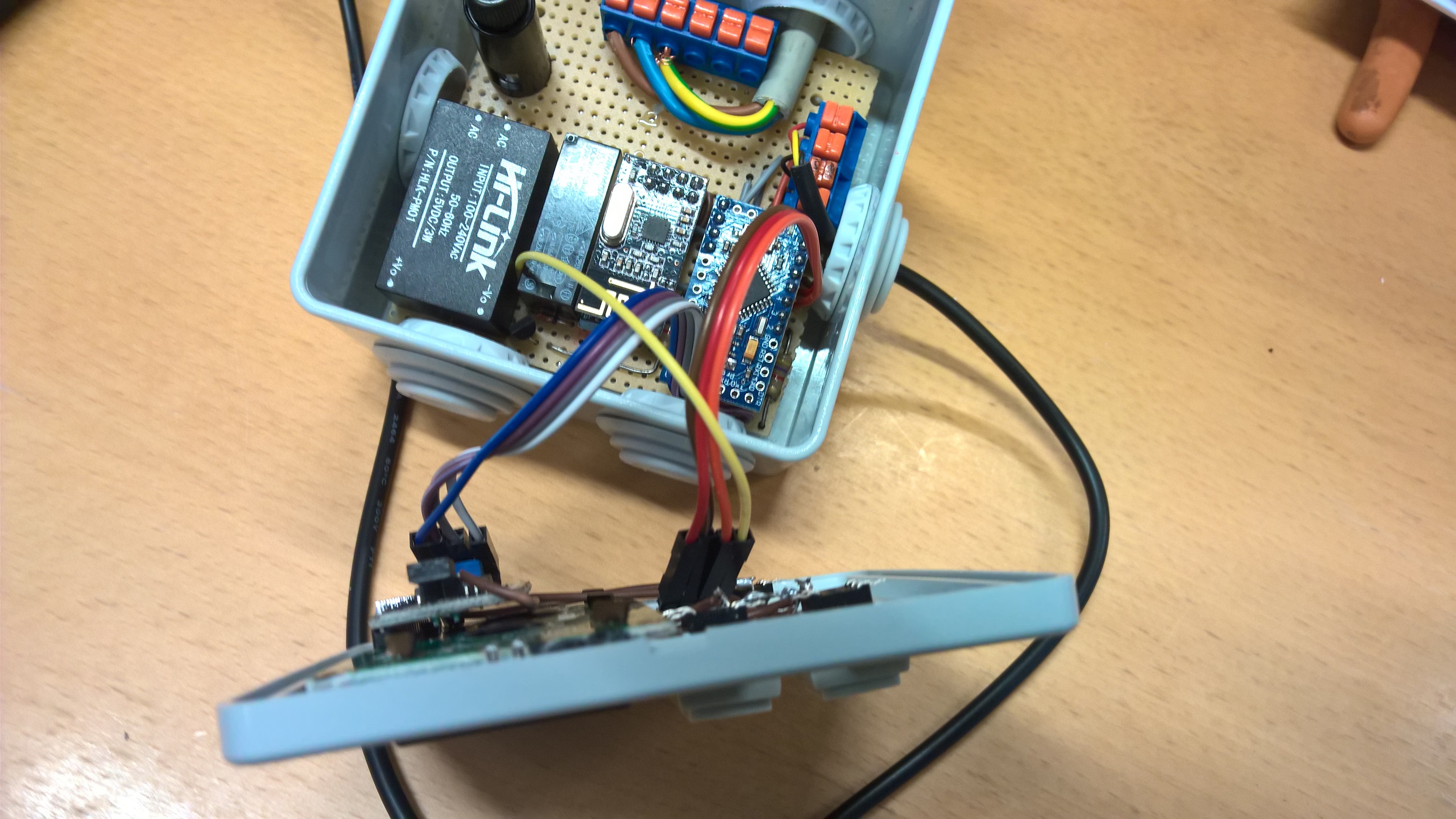
Any pictures of your masterpiece? -
Hi @korttoma ,
I am using a MAX6675 to measure the temperature of the smoke. I simply trig a flag at a falling smoke temperature under a certain level while the boiler is still warm. Then I reset it as the smoke temperature reaches a higher temperature again.It was a bit tricky to combine the example sketches to be able to connect both the DS18B20's and the MAX6675 to the same node, but I finally managed somehow. Perhaps there is still some bug in my sketch making it hard to restart after a power outage, I sometimes have to disconnect/connect the power a couple of times before the nodes starts to work again as intended. In the beginning the temperature sensors could get mixed up after a power outage, but then I implemented some kind of static addressing for the DS18B20's (mentioned somewhere else in this forum) and the mix up stopped.
Tobias
@tkarlsson I have an MAX6675 and a MAX31865 (for PT100/PT1000 type sensors) on the way. Don't know yet which one I will be using.
At the moment I have also a DS18B20 node with 3 sensors attached monitoring the tank (with static addressing).
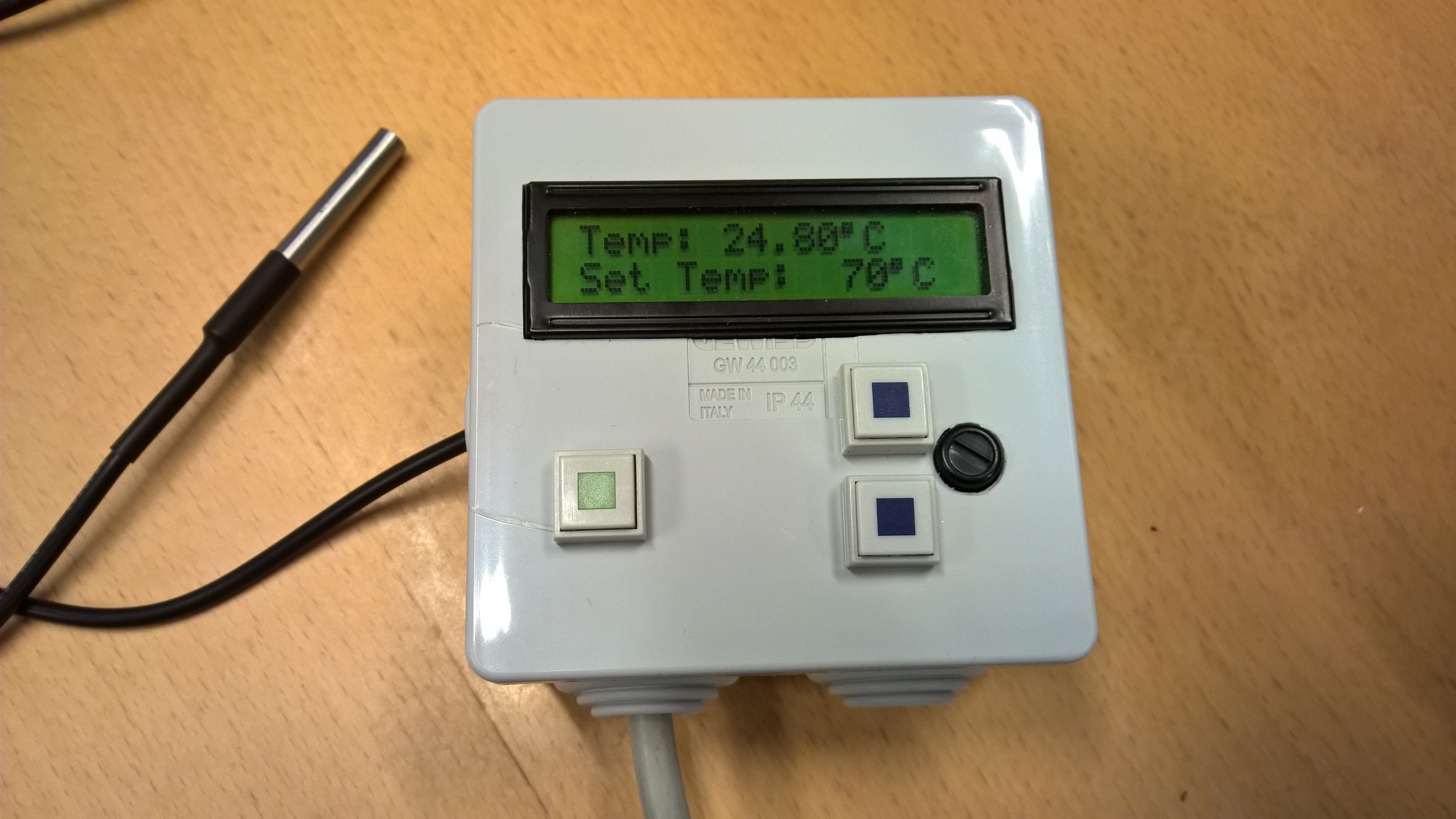
Have had no problems with this node so I think I will not touch it and make a separate node for the smoke temp.I also have a thermostat node controlling the pump between the heater and the tank (The Danfoss I was using before was unreliable and would cause my heater to boil from time to time).
I would love it if you could at some point also share the sketch for your node and pictures are always nice.
- Tomas
-
Very nice @tkarlsson, thanks for sharing!
Would you mind posting what your graphs look like?@mfalkvidd,
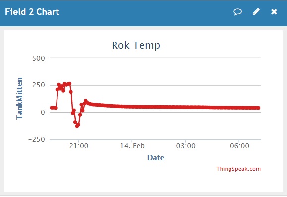
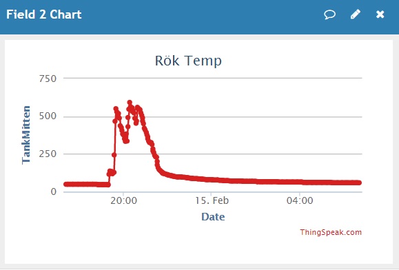
Sure I can share some graphs. Unfortunately they are in Swedish though.
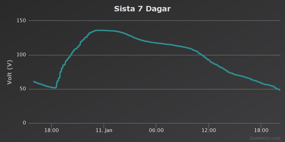
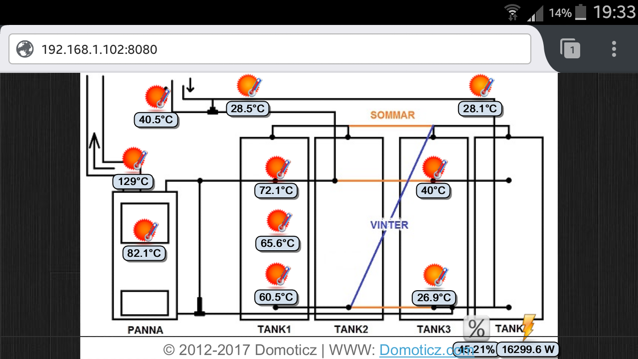
This is a graph showing 7 out of 10 temperatures from this node.The graph is showing about 24 hrs and the wood boiler is fired up in the beginning.
I guess you can see which curve is the smoke gas temp :)
That one is the first to rise, then the boiler itself, later the sensors in the top-middle-bottom of the first accumulator tank and at last the top-bottom of the second tank. The tanks are connected in series (in the winter).
As I wrote, I also try to calculate charge/discharge power, the accumulated energy in kWh and % in the accumulator tanks as good as I can using my 5 temp sensors. I consider room temp (22degreesC) as my zero kWh level and then I calculate the energy using temperatures and a certain water volume corresponding to each temperature sensor. This is a "kWh graph" from about the same period:
All calculations are made in Domoticz and not in the Mysensor nodes.
I happen to have copies of the sketches at another location so cannot share them at the moment. I am sure they are even a bit outdated by now (definitely pre 2.0).
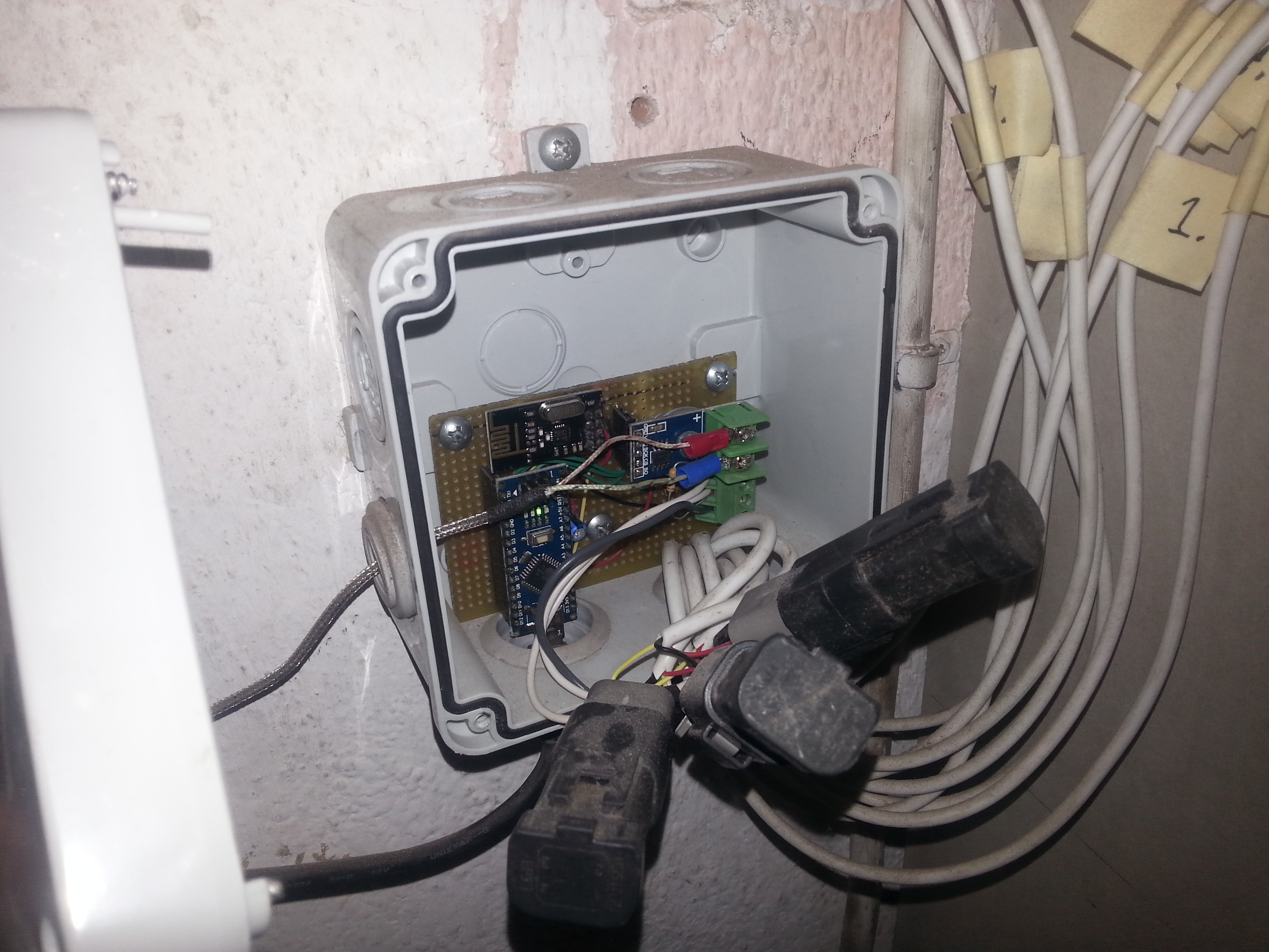
Perhaps, another day, I will click some photos of my installation. Nothing much to see, really. Part of it is behind a layer of insulation. But it is working great!
/Tobias
-
@tkarlsson I have an MAX6675 and a MAX31865 (for PT100/PT1000 type sensors) on the way. Don't know yet which one I will be using.
At the moment I have also a DS18B20 node with 3 sensors attached monitoring the tank (with static addressing).
Have had no problems with this node so I think I will not touch it and make a separate node for the smoke temp.I also have a thermostat node controlling the pump between the heater and the tank (The Danfoss I was using before was unreliable and would cause my heater to boil from time to time).
I would love it if you could at some point also share the sketch for your node and pictures are always nice.
-
@mfalkvidd,
Sure I can share some graphs. Unfortunately they are in Swedish though.
This is a graph showing 7 out of 10 temperatures from this node.The graph is showing about 24 hrs and the wood boiler is fired up in the beginning.
I guess you can see which curve is the smoke gas temp :)
That one is the first to rise, then the boiler itself, later the sensors in the top-middle-bottom of the first accumulator tank and at last the top-bottom of the second tank. The tanks are connected in series (in the winter).As I wrote, I also try to calculate charge/discharge power, the accumulated energy in kWh and % in the accumulator tanks as good as I can using my 5 temp sensors. I consider room temp (22degreesC) as my zero kWh level and then I calculate the energy using temperatures and a certain water volume corresponding to each temperature sensor. This is a "kWh graph" from about the same period:
All calculations are made in Domoticz and not in the Mysensor nodes.
I happen to have copies of the sketches at another location so cannot share them at the moment. I am sure they are even a bit outdated by now (definitely pre 2.0).
Perhaps, another day, I will click some photos of my installation. Nothing much to see, really. Part of it is behind a layer of insulation. But it is working great!
/Tobias
-
Great work how do you send error messages from a MySensors node. I'm building a solar hot water heater for my shop with temp sensors inside, outside, solar panel, storage tank, and the attic, I also have flow and pressures sensors in the tank pump solar panel and another tank pump and inside heat exchanger. Besides the pumps I also control attic, ceiling and roof louvers and fans. Needless to say there's lots that could go wrong. If you've got a way to send alarms I would love to see the Sketches. Thanks.
I would also like to see pictures of setup I think many other would also.
-
Finally got a MAX31865 + PT100 on a breadboard set up and measuring the smoke temperature.
But I seem to have an issue, either there is something wrong with the library I'm using or the sensor just cant handle the heat. If it gets hot enough I get negative values.
The boileroom is not quite fit for debugging, would be nice to have a wireless serial port of some kind.
EDIT: Maybe I can use a 470ohm potentiometer to debug this instead of the PT100?
- Tomas
-
Finally got a MAX31865 + PT100 on a breadboard set up and measuring the smoke temperature.
But I seem to have an issue, either there is something wrong with the library I'm using or the sensor just cant handle the heat. If it gets hot enough I get negative values.
The boileroom is not quite fit for debugging, would be nice to have a wireless serial port of some kind.
EDIT: Maybe I can use a 470ohm potentiometer to debug this instead of the PT100?
@korttoma said in Monitoring a wood boiler heating system:
Finally got a MAX31865 + PT100 on a breadboard set up and measuring the smoke temperature.
But I seem to have an issue, either there is something wrong with the library I'm using or the sensor just cant handle the heat. If it gets hot enough I get negative values.
Could it be something that you store your read value in a too small variable, so that you get variable rollover?
-
@bjacobse I hope so, I got it on my desk now. Just need to get the variable resistor today so I can start debugging.
/**
 * The MySensors Arduino library handles the wireless radio link and protocol
 * between your home built sensors/actuators and HA controller of choice.
 * The sensors forms a self healing radio network with optional repeaters. Each
 * repeater and gateway builds a routing tables in EEPROM which keeps track of the
 * network topology allowing messages to be routed to nodes.
 *
 * Created by Henrik Ekblad <henrik.ekblad@mysensors.org>
 * Copyright (C) 2013-2015 Sensnology AB
 * Full contributor list: https://github.com/mysensors/Arduino/graphs/contributors
 *
 * Documentation: http://www.mysensors.org
 * Support Forum: http://forum.mysensors.org
 *
 * This program is free software; you can redistribute it and/or
 * modify it under the terms of the GNU General Public License
 * version 2 as published by the Free Software Foundation.
 *
 *******************************
 *
 * DESCRIPTION
 *
 * Example sketch showing how to send in DS1820B OneWire temperature readings back to the controller
 * http://www.mysensors.org/build/temp
 */


// Enable debug prints to serial monitor
//#define MY_DEBUG

// Enable and select radio type attached
#define MY_RADIO_NRF24
//#define MY_RADIO_RFM69
//#define MY_RFM69_FREQUENCY RF69_433MHZ

// Define a static node address, remove if you want auto address assignment
#define MY_NODE_ID 23

#include <SPI.h>
#include <MySensors.h>

#include <Adafruit_MAX31865.h>

#define CHILD_ID 1

// Use software SPI: CS, DI, DO, CLK
//Adafruit_MAX31865 max = Adafruit_MAX31865(10, 11, 12, 13);
// use hardware SPI, just pass in the CS pin
Adafruit_MAX31865 max = Adafruit_MAX31865(8);

// The value of the Rref resistor. Use 430.0!
#define RREF 430.0

#define TEMP_TRANSMIT_THRESHOLD 2

float temperature;
float lastTemperature = 10;
float diffTemp = 1;
unsigned long SLEEP_TIME = 20000; // Sleep time between reads (in milliseconds)


bool receivedConfig = false;
bool metric = true;
// Initialize temperature message
MyMessage msg(CHILD_ID,V_TEMP);

void before()
{
  max.begin(MAX31865_3WIRE);  // set to 2WIRE or 4WIRE as necessary
}

void setup()
{

}

void presentation() {
  // Send the sketch version information to the gateway and Controller
  sendSketchInfo("PT100 Temp", "1.0");

     present(CHILD_ID, S_TEMP);

}

void loop() {

  uint16_t rtd = max.readRTD();

  Serial.print("RTD value: "); Serial.println(rtd);
  float ratio = rtd;
  ratio /= 32768;

  Serial.print("Ratio = "); Serial.println(ratio,8);

  Serial.print("Resistance = "); Serial.println(RREF*ratio,8);


  // Fetch temperature
  temperature = max.temperature(100, RREF);
  Serial.print("Temperature = "); Serial.println(temperature);
    // Only send data if temperature has changed and no error
  diffTemp = abs(lastTemperature - temperature);

  Serial.print("DiffTemp = "); Serial.println(diffTemp);

    if (diffTemp > TEMP_TRANSMIT_THRESHOLD) {
      // Send in the new temperature
      send(msg.set(temperature,1));
      // Save new temperatures for next compare
      lastTemperature = temperature;
    }
  sleep(SLEEP_TIME);
}
In the meantime I replaced it with a node that uses a K-Type thermocouple and this one works just fine.
-
I can now confirm that the problem is in fact the PT100 sensor because if I "simulate" the sensor with a variable resistor everything works fine all the way up to 988.8 degrees and down to -241.3.
Seems like I will have to use the K-Type sensor after all.
-
I can now confirm that the problem is in fact the PT100 sensor because if I "simulate" the sensor with a variable resistor everything works fine all the way up to 988.8 degrees and down to -241.3.
Seems like I will have to use the K-Type sensor after all.
-
Finally got a MAX31865 + PT100 on a breadboard set up and measuring the smoke temperature.
But I seem to have an issue, either there is something wrong with the library I'm using or the sensor just cant handle the heat. If it gets hot enough I get negative values.
The boileroom is not quite fit for debugging, would be nice to have a wireless serial port of some kind.
EDIT: Maybe I can use a 470ohm potentiometer to debug this instead of the PT100?
-
@korttoma just being curious: how did you install that smoke sensor? drill an hole into the chimney?
@enlo there was a hole on the back of the wood boiler where the pipe goes to the chimney.
It looked like a bolt and when I unscrewed it with a 14mm wrench I found that it had 12mm (or 1/2") threading so the hole was quite big and I can fit most sensors in it..
Because the sensor is so close to the boiler it gets quite hot so it is actually not a surprise that the sensor could not handle it but the behaviour was quite strange. I thought that if it would fail it would also destroy the sensor but it just malfunctions and goes back to normal when it cools down.The sensor claimed to have a measurement range of -200~500 Degrees like most of the sensors for sale.
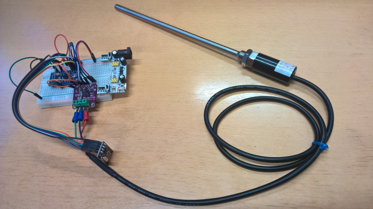
The K-Type thermocouple I'm using now has "Operating Temperature: 0 – 800 °C" but the item on Ali is nolonger available. I looks like this one though ->
-
@korttoma just being curious: how did you install that smoke sensor? drill an hole into the chimney?
@enlo
I would assume to drill a hole in the metal chimney that is between the wood boiler and the brick chimney.
then depending of the K-type thermocouple
then there is a nut so you can secure this like this:
https://www.aliexpress.com/item/Newest-High-Temperature-100-To-1250-Degree-Thermocouple-K-Type-100mm-Stainless-Steel-Probe-Sensors/32786956791.html?spm=2114.40010308.4.1.LxioyKOr else you can sealed with special heat resistant seal:
https://www.amazon.co.uk/Heat-Resistant-Sealant-1250-300ml/dp/B0046450C4 -
I just put the sensor through a 1cm sheet of heat resistant rockwool.
I bet that the draft of the chimney is enough to ensure that the fire does not find it's way through this little hole. -
@enlo there was a hole on the back of the wood boiler where the pipe goes to the chimney.
It looked like a bolt and when I unscrewed it with a 14mm wrench I found that it had 12mm (or 1/2") threading so the hole was quite big and I can fit most sensors in it..
Because the sensor is so close to the boiler it gets quite hot so it is actually not a surprise that the sensor could not handle it but the behaviour was quite strange. I thought that if it would fail it would also destroy the sensor but it just malfunctions and goes back to normal when it cools down.The sensor claimed to have a measurement range of -200~500 Degrees like most of the sensors for sale.
The K-Type thermocouple I'm using now has "Operating Temperature: 0 – 800 °C" but the item on Ali is nolonger available. I looks like this one though ->
-
Hi, all this is awesome, about the same what I would like to make as I'm heating the house with wood boiler (actually wood gasification boiler to be correct), and accumulation tank. Still working on hot water boiler, but that's not far.
For now, I got working Individually DS18b20 node (still with automatic addressing) and one node that reads the temperature in my boilers second burning chamber with a k-type thermocouple but still struggling to get them bout working with one node.
It would be very helpful for some guidance or example for this.So my goal is to get 2x thermocouples (additional for smoke temperatures) and some 18b20s in one node + some standard stuff what I am not still sure about.
But for now big thanks to mysensors team and community for this.
Hello! It looks like you're interested in this conversation, but you don't have an account yet.
Getting fed up of having to scroll through the same posts each visit? When you register for an account, you'll always come back to exactly where you were before, and choose to be notified of new replies (either via email, or push notification). You'll also be able to save bookmarks and upvote posts to show your appreciation to other community members.
With your input, this post could be even better 💗
Register Login