💬 Livolo 3 buttons US/AU switch adapter
-
@Nca78 - great, thanks! I don't mind soldering all of them, just wasn't sure if I needed to buy the specific type/package. Is the voltage regulator (SOT23-3) only necessary if I want to encrypt the messages?
@achurak1 said in 💬 Livolo 3 buttons US/AU switch adapter:
@Nca78 - great, thanks! I don't mind soldering all of them, just wasn't sure if I needed to buy the specific type/package. Is the voltage regulator (SOT23-3) only necessary if I want to encrypt the messages?
It's the ATSHA204A chip, used to sign the messages (not encrypt them). So yes if you're not planning to sign the messages you don't need to solder it. You could also use software signing but at 1MHz it could be slow, I have never tested.
-
Found a bug :(
Small one, one connection was not good in the schema so the resistor of the "extra" led 3 has no ground connection and the led cannot be used.Everything runs on the bench (touch buttons, other leds, output pins for relays),
I need to test in the wall switch now, but I'm afraid the sensitivity for the button below the radio (1) is still not good enough. -
Not too bad ! I will still improve a bit the button at the bottom (behind the radio) because it's not perfect, but it's still usable as you can see in the video :)
https://youtu.be/1LaFgjvSPj4 -
Not too bad ! I will still improve a bit the button at the bottom (behind the radio) because it's not perfect, but it's still usable as you can see in the video :)
https://youtu.be/1LaFgjvSPj4 -
@Nca78 - great news indeed! So you think it's OK to order the PCBs? Did you fix the bug with the resistor or I should add the ground connection myself before ordering the PCBs?
Did you test it with the dimmable switch by the way?@achurak1 said in 💬 Livolo 3 buttons US/AU switch adapter:
@Nca78 - great news indeed! So you think it's OK to order the PCBs? Did you fix the bug with the resistor or I should add the ground connection myself before ordering the PCBs?
Did you test it with the dimmable switch by the way?I fixed but didn't publish. I'll reduce size of traces and pads of nrf24 to improve touch performance on the button below the radio. Sometimes (after long period without use) it doesn't react well and I have to use thumb to trigger it, I think because of the auto calibration of the TTP223, so I also have to test that with different caps to adjust sensitivity and see if it improves.
I didn't test with dimmable switch yet, I'll try to do it on Monday.
So my advice : do not order yet ;) -
@Nca78 - great news indeed! So you think it's OK to order the PCBs? Did you fix the bug with the resistor or I should add the ground connection myself before ordering the PCBs?
Did you test it with the dimmable switch by the way?@achurak1 I have some good news and some bad news.
The bad news first :
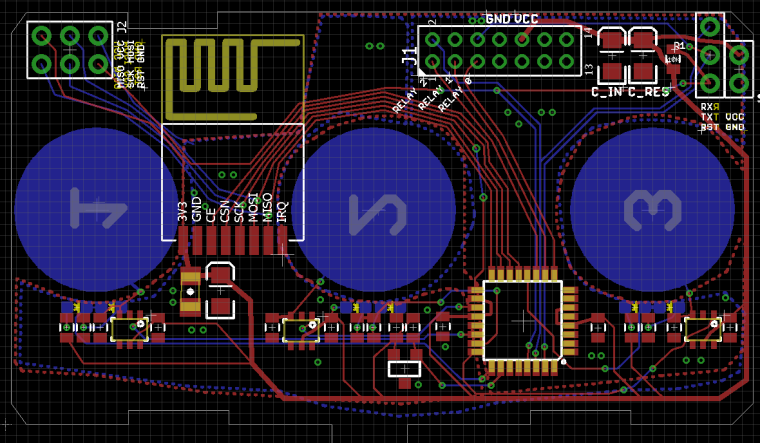
- I decided to redo all the layout of the PCB, this is the only way to be sure to solve completely the touch problem
- Related to this I have changed LED size to 0603, hope it's not a problem for you and you didn't order too many 0805 leds ? Not sure about the size of resistors and capacitors yet.
- the main PCB of the dimmer switch cannot be triggered using the "relay" pins of the touch PCB. The layout and connections on the touch PCB are exactly the same for dimmer and relay switches to save money in production, but programming of the PIC is different and "relay" pins are not connected to the dimmer main PCB.
The good news :
- Layout will be much more clean with components properly aligned and oriented
- I'm using 0603 LEDs so I can put them at the same position than original Livolo board and try to reuse the plastic diffusers
- from what I see, the 2 PICs are using UART to communicate (RX->TX and TX->RX connections), but there's also a digital pin connected so I have to check how it is used. Maybe to wake up the PWM PIC on main PCB before passing it some commands. Anyway I have TX/RX pins around this side of the connector so I can connect them and manage the dimmers when I have figured out the protocol.
-
@achurak1 I have some good news and some bad news.
The bad news first :
- I decided to redo all the layout of the PCB, this is the only way to be sure to solve completely the touch problem
- Related to this I have changed LED size to 0603, hope it's not a problem for you and you didn't order too many 0805 leds ? Not sure about the size of resistors and capacitors yet.
- the main PCB of the dimmer switch cannot be triggered using the "relay" pins of the touch PCB. The layout and connections on the touch PCB are exactly the same for dimmer and relay switches to save money in production, but programming of the PIC is different and "relay" pins are not connected to the dimmer main PCB.
The good news :
- Layout will be much more clean with components properly aligned and oriented
- I'm using 0603 LEDs so I can put them at the same position than original Livolo board and try to reuse the plastic diffusers
- from what I see, the 2 PICs are using UART to communicate (RX->TX and TX->RX connections), but there's also a digital pin connected so I have to check how it is used. Maybe to wake up the PWM PIC on main PCB before passing it some commands. Anyway I have TX/RX pins around this side of the connector so I can connect them and manage the dimmers when I have figured out the protocol.
@Nca78 - only 500 pieces :) That's OK though, they're cheap, I already ordered the 0603 ones, just hoping my soldering skills are going to be enough for that size. Let me know as soon as you decide on the res/cap packages. I have only 0805, but can order something else if needed.
Thanks for keeping me in the loop and hope you will be able to crack that protocol! -
@Nca78 - only 500 pieces :) That's OK though, they're cheap, I already ordered the 0603 ones, just hoping my soldering skills are going to be enough for that size. Let me know as soon as you decide on the res/cap packages. I have only 0805, but can order something else if needed.
Thanks for keeping me in the loop and hope you will be able to crack that protocol!@achurak1 I managed to keep everything else in the same size, that's more convenient for me to solder too :D
Nearly finished, I'll try to see tomorrow how the 2 boards discuss, then connect necessary digital pins and put back extra leds with the pins I have left.
-
Unfortunately it's not that easy to understand. After double checking I realized they connected TX to TX and RX to RX so it's not serial communication.
I'm trying to check with logic analyser but I'm not very talented with that :D -
Unfortunately it's not that easy to understand. After double checking I realized they connected TX to TX and RX to RX so it's not serial communication.
I'm trying to check with logic analyser but I'm not very talented with that :D@Nca78 said in 💬 Livolo 3 buttons US/AU switch adapter:
In the livolo EU board, the RX and TX pin are for the radio. It's the same PCB all the time, they just put or not the 433MHZ radio ;)
-
@Nca78 said in 💬 Livolo 3 buttons US/AU switch adapter:
In the livolo EU board, the RX and TX pin are for the radio. It's the same PCB all the time, they just put or not the 433MHZ radio ;)
@tonnerre33 but they are connected to the PIC MCU on the main PCB, that would make no sense if those pins were used with the radio ?
-
And I have synchronized signals on the 3 pin too (TX, RX and RB4 pin). The TX and RX pins are obviously those used for communication as the signal on those pin always follow a level change on RB4 pin.
-
@tonnerre33 but they are connected to the PIC MCU on the main PCB, that would make no sense if those pins were used with the radio ?
@Nca78 said in 💬 Livolo 3 buttons US/AU switch adapter:
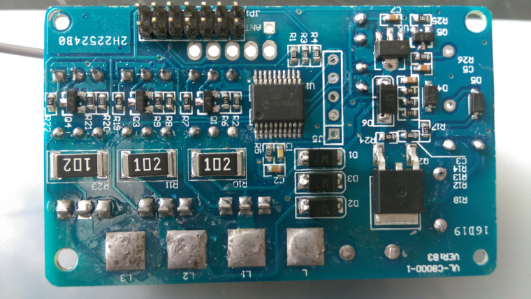
It's true. Can you take a picture of you pic mcu main board ? It's for compare with my EU board ;) -
@Nca78 said in 💬 Livolo 3 buttons US/AU switch adapter:
It's true. Can you take a picture of you pic mcu main board ? It's for compare with my EU board ;)@tonnerre33 sure, here you are.
Pins I'm checking with the logic analyser are connected to the PIC using the R1, R3, R4 200 Ohms resistors (top right of the PIC) they are the only ones I see connected to the PIC.
-
So maybe I will need help/advice from someone who has a bit of knowledge about this kind of data exchange between 2 processors, to see if it rings a bell for them... @scalz maybe (sorry to bother you :))
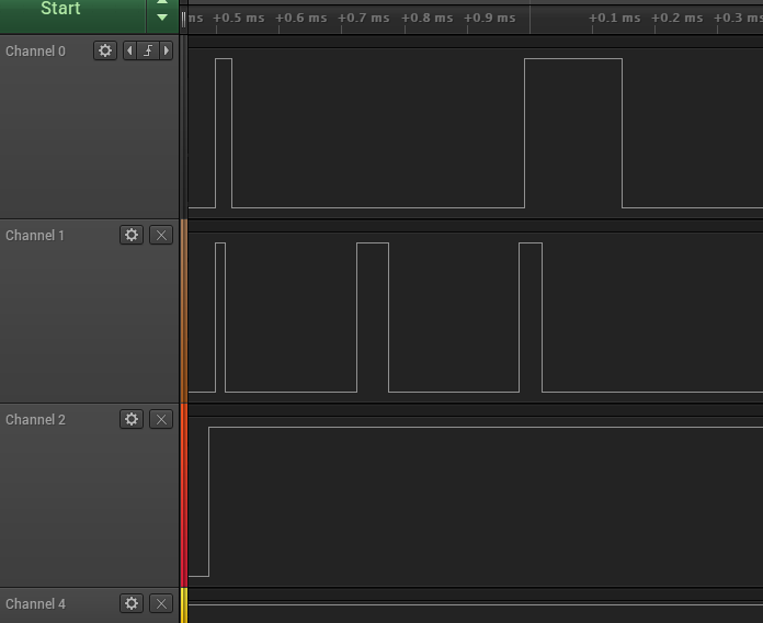
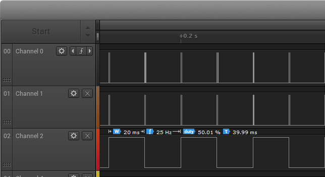
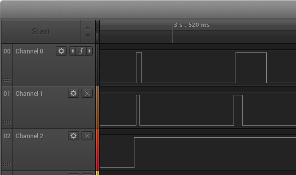
Channel 2 is connected to RA4 (touch PCB PIC) and RB4 (main PCB PIC). It's obviously a clock signal, at 25Hz, 50% duty cycle. Each edge (raising and falling) generates pulses on the 2 other pins.
Channel 0 is connected to pin RB7/TX/CK.
Channel 1 is connected to pin RB5/AN11/RX/DT
What I see is this base signal, with some pulse that are always repeated every 20ms:- edge on C2 triggers pulses on C0 and C1 (both at the same time) with a 12us delay. I call them "start" pulses later.
- C1 pulse lasts 16us, it's falling edge triggers a falling edge on C0 with 10us delay
- after 260us there is another pulse on C1, triggering another pulse on C0 with a 10us delay. I call them "end" pulses later.
- C1 pulse last 40us, C0 pulse 152us
- duration between start and end pulses is always the same (468us)
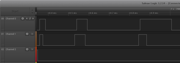
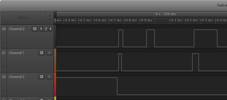
Adding to that base signal, I have some "extra" pulses that appear between the start/end pulses, in 3 different
- pulse on C1 208us after start pulse ,
- pulse on C1 208us after start pulse, followed 10us later by another pulse on C0 with 10us delay
- pulso on C1 156us after start pulse, no pulse on C1. I've seen this case only once. Signal repeated 7 times then
I have not seen the case where a pulse on C1 happens after a pulse on C0, but maybe it happened and I just missed it as it's pretty hard to search in the logic software for this case ...
As the pulses always have the same duration, my stupid guess is middle pulse between start end end pulse = 1, no middle pulse = 0. Plausible ? Not ? Anything specific I should check ?
Any suggestion is welcome :)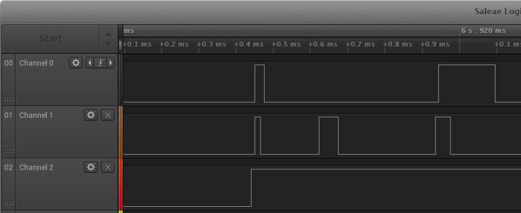
-
@Nca78 - only 500 pieces :) That's OK though, they're cheap, I already ordered the 0603 ones, just hoping my soldering skills are going to be enough for that size. Let me know as soon as you decide on the res/cap packages. I have only 0805, but can order something else if needed.
Thanks for keeping me in the loop and hope you will be able to crack that protocol!@achurak1 I'll give up on the dimmer at the moment as I need to spend more time on my NModule projects.
I kept TX and RX pins connected as they can be used as normal digital pins, and I connected D3 to what I see is the clock pin so it should be possible to use dimmers in the future.
I have 3 extra LEDs in place but #4 is challenging to route so maybe I will not put it.
I'm thinking about a version with ws2812b too as it would be much more convenient than those extra LEDs, both to route and to use. -
@Nca78
sorry i miss time to take a look at your project actually. will do it later if i can, as it's always easier with the hardware for debugging this. I don't have this livolo version, only a one button version, but i'm still wondering how much it costs to use a Livolo+custom made mysensors board VS redesigning completely one -
@Nca78
sorry i miss time to take a look at your project actually. will do it later if i can, as it's always easier with the hardware for debugging this. I don't have this livolo version, only a one button version, but i'm still wondering how much it costs to use a Livolo+custom made mysensors board VS redesigning completely one@scalz said in 💬 Livolo 3 buttons US/AU switch adapter:
@Nca78
sorry i miss time to take a look at your project actually. will do it later if i can, as it's always easier with the hardware for debugging this. I don't have this livolo version, only a one button version, but i'm still wondering how much it costs to use a Livolo+custom made mysensors board VS redesigning completely oneThank you but I just wanted to know if you had seen something like that before ? Any lead to protocole/example/anything that could make me on the right track (or not, as long as I learn something I won't complain) is welcome :)
For redesigning one, well this kind of power supply using live wire only is beyond my knowledge at the moment, and I can't pull neutral wire to have it in my switches. For around 20€ delivered for a full Livolo switch it costs 25-30€ to have a MySensors version, I'm not sure there's much money to save
-
@scalz said in 💬 Livolo 3 buttons US/AU switch adapter:
@Nca78
sorry i miss time to take a look at your project actually. will do it later if i can, as it's always easier with the hardware for debugging this. I don't have this livolo version, only a one button version, but i'm still wondering how much it costs to use a Livolo+custom made mysensors board VS redesigning completely oneThank you but I just wanted to know if you had seen something like that before ? Any lead to protocole/example/anything that could make me on the right track (or not, as long as I learn something I won't complain) is welcome :)
For redesigning one, well this kind of power supply using live wire only is beyond my knowledge at the moment, and I can't pull neutral wire to have it in my switches. For around 20€ delivered for a full Livolo switch it costs 25-30€ to have a MySensors version, I'm not sure there's much money to save
-
@Nca78 - Hi! Haven't heard from your for quite some time :) Any progress with this? Were you able to resolve the poor sensitivity issues?
@achurak1 said in 💬 Livolo 3 buttons US/AU switch adapter:
@Nca78 - Hi! Haven't heard from your for quite some time :) Any progress with this? Were you able to resolve the poor sensitivity issues?
Hello !
Sorry I'm testing NModule and all shields at the moment.
Then I'll work on this again and make some PCBs.
Hello! It looks like you're interested in this conversation, but you don't have an account yet.
Getting fed up of having to scroll through the same posts each visit? When you register for an account, you'll always come back to exactly where you were before, and choose to be notified of new replies (either via email, or push notification). You'll also be able to save bookmarks and upvote posts to show your appreciation to other community members.
With your input, this post could be even better 💗
Register Login