💬 RFM69(H)W Arduino Mini Pro Shield
-
@NeverDie - Its called "Via Stitching" http://techdocs.altium.com/display/ADOH/Via+Stitching#
Could the author add design files as well (not only gerber?).
Im interested in the RFM antenna design. Do you have any library used for the RFM module as well?@sundberg84 said in 💬 RFM69(H)W Arduino Mini Pro Shield:
@NeverDie - Its called "Via Stitching" http://techdocs.altium.com/display/ADOH/Via+Stitching#
When it comes to RF, it seems like there are competing theories floating around. I guess via stitching is one theory. Another theory is that you want the ground plane to be as uninterrupted as possible. I've also seen a theory that says you want to have only one point of connection between nets. I'm not sure how to resolve all that, except by experimentation. That's why I'm glad the OP machine gunned his board with via's: it's something new to try for a compare/contrast. Since it doesn't add to cost, I'd be delighted if it turns out to be beneficial.
-
@sundberg84 said in 💬 RFM69(H)W Arduino Mini Pro Shield:
@NeverDie - Its called "Via Stitching" http://techdocs.altium.com/display/ADOH/Via+Stitching#
When it comes to RF, it seems like there are competing theories floating around. I guess via stitching is one theory. Another theory is that you want the ground plane to be as uninterrupted as possible. I've also seen a theory that says you want to have only one point of connection between nets. I'm not sure how to resolve all that, except by experimentation. That's why I'm glad the OP machine gunned his board with via's: it's something new to try for a compare/contrast. Since it doesn't add to cost, I'd be delighted if it turns out to be beneficial.
@NeverDie said in 💬 RFM69(H)W Arduino Mini Pro Shield:
@sundberg84 said in 💬 RFM69(H)W Arduino Mini Pro Shield:
@NeverDie - Its called "Via Stitching" http://techdocs.altium.com/display/ADOH/Via+Stitching#
When it comes to RF, it seems like there are competing theories
not competing, i would say complementary :)
-
Hi,
Neat project. This will really make for much cleaner projects for me.
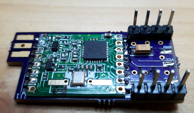
I ordered a few to play with and I'm trying to understand the connections. I soldered the RFM69 module on, no problem, and the antenna. I'll do the capacitor next.
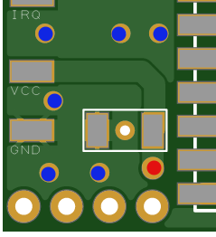
However, I'm trying to figure out the GND, VCC, and IRQ connections. Are the pads the only option for connection, or do the holes next to them work too (hole a lot easier to solder than pad :-)) ? I don't see any kind of etching connecting the two visible on either the top or the bottom. I assume the intent is to connect a wire to them and then run that wire "underneath" the mini to connect to GND, VSS, and D2 respectively?
Sorry if that's a stupid question, as I don't have tools to via the design files.
--Steve
-
Hi,
Neat project. This will really make for much cleaner projects for me.
I ordered a few to play with and I'm trying to understand the connections. I soldered the RFM69 module on, no problem, and the antenna. I'll do the capacitor next.
However, I'm trying to figure out the GND, VCC, and IRQ connections. Are the pads the only option for connection, or do the holes next to them work too (hole a lot easier to solder than pad :-)) ? I don't see any kind of etching connecting the two visible on either the top or the bottom. I assume the intent is to connect a wire to them and then run that wire "underneath" the mini to connect to GND, VSS, and D2 respectively?
Sorry if that's a stupid question, as I don't have tools to via the design files.
--Steve
Glad the project seems interesting, the possibility to it being useful to someone else is the main reason for sharing.
Regarding the connections, for GND, you can connect to any of the blue dots, for VCC to the red dot, IRQ has no option other than the pad.
My idea in using the pads was to make the board easier to slide below the mini, exactly like you state.
If you want, i can create a custom board for you with hole instead of pad, i used designspark PCB which is easy(er) to use but does not allow to export to other PCB software formats :-(. -
Thanks for the quick reply. No need for special build for IRQ (although that might be a good addition for a future rev to have that option). I can solder to a pad, it's just trickier as my E.E. training, skills, steadier hands, and better eyesight were 20+ years ago :-)
For the holes, out of curiosity, I see the VCC hole connection trace on the board, but I can't see how the pins are all connected to GND (i.e. can't see any traces). Is it between the layers of the board? Or am I just going blind?
Thanks again for the contribution as this is a very nice project.
-
Thanks for the quick reply. No need for special build for IRQ (although that might be a good addition for a future rev to have that option). I can solder to a pad, it's just trickier as my E.E. training, skills, steadier hands, and better eyesight were 20+ years ago :-)
For the holes, out of curiosity, I see the VCC hole connection trace on the board, but I can't see how the pins are all connected to GND (i.e. can't see any traces). Is it between the layers of the board? Or am I just going blind?
Thanks again for the contribution as this is a very nice project.
@stevebus you are going blind :-D (like me probably) all those pins are in the ground plane, trying to provide a uniform ground to see if it improves the performance of the radio (by reducing outside interference). You can see that clearly on the gnd of the capacitor or in the gnd pad.
-
Ah! I see! (said the blind man :-) ).
I had never really paid attention to PCB design, so didn't realize there were often "planes" for some widespread connections (like ground)... makes perfect sense.
Thx again for the quick responses. I'll be soldering up the rest of the connections tomorrow so I'll be able to give it a test.
-
@stevebus you are going blind :-D (like me probably) all those pins are in the ground plane, trying to provide a uniform ground to see if it improves the performance of the radio (by reducing outside interference). You can see that clearly on the gnd of the capacitor or in the gnd pad.
-
@jlaraujo I am about to order sma connectors, is there anything to look for or anyone would do?
@gohan - use the same size on the connector as you have when you order the boards ;)
-
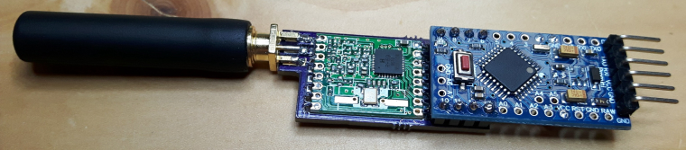
Was able to finish up the soldering, and just playing with the mocksensor sketch... works great! (not sure why my pics are sideways, they are straight on my machine :-) )
Looking at the RSSI data, this sensor seems to be about the same signal strength as my other sensors (maybe even slightly better, probably due to the shorter and more solid connections). So it seems that the performance of the radio is pretty good.


-
If you can find the size let me know, I looked on aliexpress and none are showing what is the supported pcb size. So either it is like standard for 1.6mm pcbs or I have no idea
-
Was able to finish up the soldering, and just playing with the mocksensor sketch... works great! (not sure why my pics are sideways, they are straight on my machine :-) )
Looking at the RSSI data, this sensor seems to be about the same signal strength as my other sensors (maybe even slightly better, probably due to the shorter and more solid connections). So it seems that the performance of the radio is pretty good.
-
If you can find the size let me know, I looked on aliexpress and none are showing what is the supported pcb size. So either it is like standard for 1.6mm pcbs or I have no idea
@gohan - I have found both 1.6mm and 1mm on Ebay. Since i like to order 1mm thats what i went with SMA connector but it was way easier to find 1.6mm. I just mean a easy misstake would be to order a 1.6mm SMA connector and 1.0mm pcb. Might probably work.
-
I really like this design as I am looking for a small for factor RFM69 shield. One question how hard would it be to integrate a connection for a DHT22 to be able to have a small temp and humidity transmitter. I need to have about 5 of these setup in different locations sending temp and humidity back to a gateway.
@556duckvader, like @gohan referred, you can attach the DHT22 to the arduino and not to the shield.
You can make a simple PCB that will connect to the required ports for the DHT22 to operate.
If you'd like to have an even smaller footprint, try this design:
https://www.openhardware.io/view/615
It is not yet tested in production, probably will be by the end of the week.
Hello! It looks like you're interested in this conversation, but you don't have an account yet.
Getting fed up of having to scroll through the same posts each visit? When you register for an account, you'll always come back to exactly where you were before, and choose to be notified of new replies (either via email, or push notification). You'll also be able to save bookmarks and upvote posts to show your appreciation to other community members.
With your input, this post could be even better 💗
Register Login