💬 Easy/Newbie PCB (RFM69 HW/W edition) for MySensors
-
Everything is going fine so im taking this to the next level... from test to produktion.
This sensor might be my most important summer sensor from now on ;)
A couple of days ago I had some friends over which gave me a beer cooler, garden edition.
Its pretty much a barrel in the ground which cools the beer down... (a bit atleast).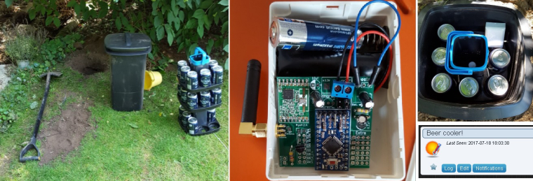
I must say Im very impressed with the RFM69 so far... except the price, there has been no trouble at all. No repeaters, no capacitors, no fine tuning... nothing. Pretty much solder 'n' play!
This node is burried in the far end on the garden (25m) and has to penetrate 3 concrete + 1brick wall to reach the GW in the celler... no problems, first try and bang!
So far... the temperature in the cooler isnt very impressive, and I have only tried the first layer. I was afraid I would loose radio coverage if I put the sensors far down... but I will try.
Cheers mates!
@sundberg84 said in 💬 Easy/Newbie PCB (RFM69 HW/W edition) for MySensors:
Everything is going fine so im taking this to the next level... from test to produktion.
This sensor might be my most important summer sensor from now on ;)
A couple of days ago I had some friends over which gave me a beer cooler, garden edition.
Its pretty much a barrel in the ground which cools the beer down... (a bit atleast).I must say Im very impressed with the RFM69 so far... except the price, there has been no trouble at all. No repeaters, no capacitors, no fine tuning... nothing. Pretty much solder 'n' play!
This node is burried in the far end on the garden (25m) and has to penetrate 3 concrete + 1brick wall to reach the GW in the celler... no problems, first try and bang!
So far... the temperature in the cooler isnt very impressive, and I have only tried the first layer. I was afraid I would loose radio coverage if I put the sensors far down... but I will try.
Cheers mates!
Hi, nice set-up. I have been reading this and havong a "newbie" question. I have a Newbie PCB build with the Nrf24l01+ which seems to give (me) a poor range.
So would that improve having a rfm69 instead? Or will just adding an antenna improve the reach (I have more or less the same outside distance and concrete wall/ flooring I'd liek to cross). Now I just have a reach for approx 8 meters and one concrete floor (inside the house)? Which is not very good (even my z-wave devices are preforming much better - outside at 20 mtr from the house.
Can the nrf240 be improved or do I need teh rfm69 (or even using a LORA ?). -
I would get better quality nrf24 modules and using a PA LNA one on the gateway may also help. Sure the rfm69 at 433MHz can have a better wall penetration, but I think you can do with better radios. Look for CDEByte store on aliexpress, they have good radio modules. Also a poor quality power supply can reduce the effective range.
If you want to try the RFM69 radios, you can "convert" the ones you have with this https://www.mysensors.org/hardware/nrf2rfm69 -
I would get better quality nrf24 modules and using a PA LNA one on the gateway may also help. Sure the rfm69 at 433MHz can have a better wall penetration, but I think you can do with better radios. Look for CDEByte store on aliexpress, they have good radio modules. Also a poor quality power supply can reduce the effective range.
If you want to try the RFM69 radios, you can "convert" the ones you have with this https://www.mysensors.org/hardware/nrf2rfm69@gohan said in 💬 Easy/Newbie PCB (RFM69 HW/W edition) for MySensors:
I would get better quality nrf24 modules and using a PA LNA one on the gateway may also help. Sure the rfm69 at 433MHz can have a better wall penetration, but I think you can do with better radios. Look for CDEByte store on aliexpress, they have good radio modules. Also a poor quality power supply can reduce the effective range.
If you want to try the RFM69 radios, you can "convert" the ones you have with this https://www.mysensors.org/hardware/nrf2rfm69So these would be better?
https://nl.aliexpress.com/item/E01-ML01DP5-Ebyte-2-4GHz-20dBm-2100m-nRF24L01-SPI-Wireless-transceiver-module/32638720689.html?spm=a2g0s.13010208.99999999.336.T3AfNk
https://nl.aliexpress.com/item/CDEBYTE-2PCS-Lot-E01-ML01D-Wireless-Transceiver-For-Arduino-nRF24L01-2-4GHz-Antenna-Module-For-Microcontroll/32803704874.html?spm=a2g0s.13010208.99999999.333.T3AfNk
https://nl.aliexpress.com/item/CDEBYTE-2PCS-Lot-Special-promotions-1800-meter-long-distance-nRF24L01-PA-LNA-wireless-modules-with-PCB/32803720600.html?spm=a2g0s.13010208.99999999.330.T3AfNkIf I use one with PA_LNA on my Gateway are the pin-out the same as for the nrf24l+ as in the mysensors gatweay example?
Also there are models with nrf24l+PA what is the difference with the nrf24l+ ones? -
Yes those. Pa stands for power amplifier, lna stands for low noise amplifier and it is used to amplify incoming signal to boost low signals. For gateway it is better to use these with the higher gain antenna, on the node it is up to you according to the size constraints you may have.
-
@gohan said in 💬 Easy/Newbie PCB (RFM69 HW/W edition) for MySensors:
I would get better quality nrf24 modules and using a PA LNA one on the gateway may also help. Sure the rfm69 at 433MHz can have a better wall penetration, but I think you can do with better radios. Look for CDEByte store on aliexpress, they have good radio modules. Also a poor quality power supply can reduce the effective range.
If you want to try the RFM69 radios, you can "convert" the ones you have with this https://www.mysensors.org/hardware/nrf2rfm69So these would be better?
https://nl.aliexpress.com/item/E01-ML01DP5-Ebyte-2-4GHz-20dBm-2100m-nRF24L01-SPI-Wireless-transceiver-module/32638720689.html?spm=a2g0s.13010208.99999999.336.T3AfNk
https://nl.aliexpress.com/item/CDEBYTE-2PCS-Lot-E01-ML01D-Wireless-Transceiver-For-Arduino-nRF24L01-2-4GHz-Antenna-Module-For-Microcontroll/32803704874.html?spm=a2g0s.13010208.99999999.333.T3AfNk
https://nl.aliexpress.com/item/CDEBYTE-2PCS-Lot-Special-promotions-1800-meter-long-distance-nRF24L01-PA-LNA-wireless-modules-with-PCB/32803720600.html?spm=a2g0s.13010208.99999999.330.T3AfNkIf I use one with PA_LNA on my Gateway are the pin-out the same as for the nrf24l+ as in the mysensors gatweay example?
Also there are models with nrf24l+PA what is the difference with the nrf24l+ ones?@mr_sensor I have the same experience. A good gateway radio is important. I also use a amplified version. Sometimes it has been poor radio clones that make the bad range as well. Even if you don't have a amplified radio 8m+ 1 wall should be possible.
-
@mr_sensor I have the same experience. A good gateway radio is important. I also use a amplified version. Sometimes it has been poor radio clones that make the bad range as well. Even if you don't have a amplified radio 8m+ 1 wall should be possible.
-
@sundberg84 @gohan Ok thanks for the input I will order some of the extended ones :) and see if thing s will improve.
@mr_sensor said in 💬 Easy/Newbie PCB (RFM69 HW/W edition) for MySensors:
@sundberg84 @gohan Ok thanks for the input I will order some of the extended ones :) and see if thing s will improve.
The parts mentioned above arrived. I thought just swapping the radio's and see if there is any improvement. But it seems my devices are not happy with there new radio :) ? So are these new devices coming with the same pin-out and are they using the same library as the non amplified radio"s ? Or do I need to alter my sketches or wiring for it to work?
-
@mr_sensor said in 💬 Easy/Newbie PCB (RFM69 HW/W edition) for MySensors:
@sundberg84 @gohan Ok thanks for the input I will order some of the extended ones :) and see if thing s will improve.
The parts mentioned above arrived. I thought just swapping the radio's and see if there is any improvement. But it seems my devices are not happy with there new radio :) ? So are these new devices coming with the same pin-out and are they using the same library as the non amplified radio"s ? Or do I need to alter my sketches or wiring for it to work?
@mr_sensor i think it should be the same pin out. Gohan might now better on the amplified version. As I said I don't use those much.
What kind of error do you have now?
-
@gohan said in 💬 Easy/Newbie PCB (RFM69 HW/W edition) for MySensors:
but this is RFM69 radio pcb not NRF24
I know but I am using the nrf24 pcb.Do I need to add something like this when using the AP version?
#define MY_RADIO_NRF24
#define MY_RF24_PA_LEVEL RF24_PA_HIGH
Or just #define MY_RADIO_NRF24
@mr_sensor correct. As I said I'm no expert with the amplified version but that looks ok. I suggest you try it out. If it's wrong you will get an error and you can post that .
-
This has now been updated to rev. 10. There are still some images left to change.
The gerbers has been updated and sent to manufacturer but it will take some days before they update.
Make sure it says rev5 before ordering.
-
This has now been updated to rev. 10. There are still some images left to change.
The gerbers has been updated and sent to manufacturer but it will take some days before they update.
Make sure it says rev5 before ordering.
@sundberg84 said in 💬 Easy/Newbie PCB (RFM69 HW/W edition) for MySensors:
This has now been updated to rev. 10. There are still some images left to change.
The gerbers has been updated and sent to manufacturer but it will take some days before they update.
Make sure it says rev5 before ordering.
Hello,
Thanks for creating these PCBs, it's great to have a stable base to work upon!
I want to make a daughter board using the MYSX connector but the pin choices are a little inconvenient. Like A0 is used by the battery voltage measure circuit, D2 is used by the RFM69 radio. Could you share your reasons for using these pins and whethe it is possible to use different pins?
Finally, I couldn't find instructions for adding the flash memory. That is a great addition to this board!
Cheers,
Birla -
@sundberg84 said in 💬 Easy/Newbie PCB (RFM69 HW/W edition) for MySensors:
This has now been updated to rev. 10. There are still some images left to change.
The gerbers has been updated and sent to manufacturer but it will take some days before they update.
Make sure it says rev5 before ordering.
Hello,
Thanks for creating these PCBs, it's great to have a stable base to work upon!
I want to make a daughter board using the MYSX connector but the pin choices are a little inconvenient. Like A0 is used by the battery voltage measure circuit, D2 is used by the RFM69 radio. Could you share your reasons for using these pins and whethe it is possible to use different pins?
Finally, I couldn't find instructions for adding the flash memory. That is a great addition to this board!
Cheers,
Birla@prakhar-birla Hi!
The reason is that MysX is a fixed connector. This way you can make daughterboards. If the pins would be inconsistent it would not work. You can use these pins (A0 + D2) if you dont use it for radio or battery measurment.
I havent had time to make instructions for the flash memory, but there are several others on this site which have made that. Look around for @scalz work for example on openhardware.io
-
@prakhar-birla Hi!
The reason is that MysX is a fixed connector. This way you can make daughterboards. If the pins would be inconsistent it would not work. You can use these pins (A0 + D2) if you dont use it for radio or battery measurment.
I havent had time to make instructions for the flash memory, but there are several others on this site which have made that. Look around for @scalz work for example on openhardware.io
Hey @sundberg84,
Thanks for the clarification! I checked the spec docs for the MYSX connectors but they didn't mention any fixed pins, just the purpose/pin type. Anyway, for different MCU it will inevitably be different pins. On Arduino Pro Mini since there are only two external interrupts there's no escaping D2, the analog pin on the other hand in an easy fix either use a different pin for battery measurement (A6/A7 is only a via away) or a different pinout on the MYSX.
I couldn't find any instructions for the flash memory, please share a link when you can. Also is it possible to add it without the footprint on the PCB?
PS. I just ordered a set of 10 PCBs through Open Hardware :)
Cheers
-
Hey @sundberg84,
Thanks for the clarification! I checked the spec docs for the MYSX connectors but they didn't mention any fixed pins, just the purpose/pin type. Anyway, for different MCU it will inevitably be different pins. On Arduino Pro Mini since there are only two external interrupts there's no escaping D2, the analog pin on the other hand in an easy fix either use a different pin for battery measurement (A6/A7 is only a via away) or a different pinout on the MYSX.
I couldn't find any instructions for the flash memory, please share a link when you can. Also is it possible to add it without the footprint on the PCB?
PS. I just ordered a set of 10 PCBs through Open Hardware :)
Cheers
@prakhar-birla - well the idea with MysX is that the pin-order is fixed so you can attach any daugherboard to it. If you start mixing the pins around you will not be able to transfer a daugherboard from one motherboard to another since they will be different. Im not sure how MysX would translate to other MCU but other have digital and analog pins as well - so it would be most possible to connect MysX to other mcu.
About the external interrupt you are right, there are 2 on the atmega328. On my Nrf24l01+ version you can use D2 as an interrupt but since the RFM69 radio uses this pin you can not on this version. D3 is your only choise and if you need more you might have to create an external circuit.
As I said, I havent had time to look over SPI flash instructions yet. I havent even tried it - this is a user request from this forum. You can search this forum for more information - like this: https://forum.mysensors.org/topic/3160/ota-flash-types-for-mysensors/
-
Hi @sundberg84, on Easy/Newbie PCB rfm69 version PIN3 of MysX connector is connected to 3.3V resp. to the output from voltage regulator. When I compare with Easy/Newbie PCB nrf24l01 version, MysX PIN3 is connected to input of voltage regulator (to 5V). Is this a mistake in design of Easy/PCB rfm69 version?