nRF5 action!
-
[Edit: skip forward toward the end of this thread for the bluetooth action. The thread started on a different topic. ]
Objective: Start with the design of the Sparkfun SAMD21 mini board (https://www.sparkfun.com/products/13664) , which is a TQFP48, and see if I can port it to the SAMD21 TQFP32. Why? Pitch on the TQFP48 is 0.5mm, whereas on the TQFP32 it's 0.8. So, I'm theorizing that the TQFP32 will be easier to solder.
Motivation: If I can get this working, then I hope to use it as a basic building block for making wireless nodes.
Approach for first attempt: I started with the Sparkfun schematic (https://cdn.sparkfun.com/datasheets/Dev/Arduino/Boards/sparkfun-samd21-mini-breakout-v10.pdf and tried maintaining the same pin mapping using the TQFP32. The result was:0_1496686682351_Schematic_for_SAMD21_TQFP32_Pro_Mini _v001.pdf
From this it becomes evident that the TQPF32 version is lacking four pins that the TQFP48 version has, namely, pins: PA20, PA21, PB08, and PB09. However, the TQFP32 version has seven pins that aren't presently being used, namely: PA05,
PA22, PA23, PA24, PA25, PA27, and PA28.So, I'm thinking I will simply use four of the seven pins to cover for the 4 pins which the TQFP32 lacks that the TQFP48 has.
Questions:
- Does it matter which of the six pins I use for this purpose?
- What is the value for the inductor shown in the sparkfun schematic? It shows "30 ohms," but shouldn't the unit of measure be in Henries?
Correction: six of those seven "unused" pins are intended for other purposes.
PA22: SDA
PA23: SCL
PA24: USB_D-
PA25: USB_D+
PA27: TX_LED
PA28: USB_HOST_ENABLEAlso, in theory PA05 is wired to A5, which doesn't have a pinout on the board.
I could probably re-assign PA27, because I don't definitely need a TX_LED. Likewise, I could re-assign PA05, because it doesn't have a pinout.
However, that leaves us two pins short.
I suppose if we were to give up the USB by using the SAMD20, we'd get another 3 pins?
I think for now I'm inclined to keep the USB connection at the cost of losing two pins. Otherwise, I'm not sure how the "two" USB connections (one for programming and one for consol) that are already mapped onto the one USB connector will get sorted out, or even if it can be.
In fact, I'm not even sure if the existing pins can be remapped or not. So, for now, I'm just going to drop 4 of the exposed pins from version 1 of the TQFP32 SAMD21 Pro Mini.
-
Doing the above leads me to version 2, which is this: 0_1496699755570_Schematic_for_SAMD21_TQFP32_Pro_Mini _v002.pdf
Wiring up USB remains to be done, but before I do that, I want to see how the layout looks, because I want to see if I can avoid using a 4-layer PCB, which is what Sparkfun did.
-
Have you checked this ?
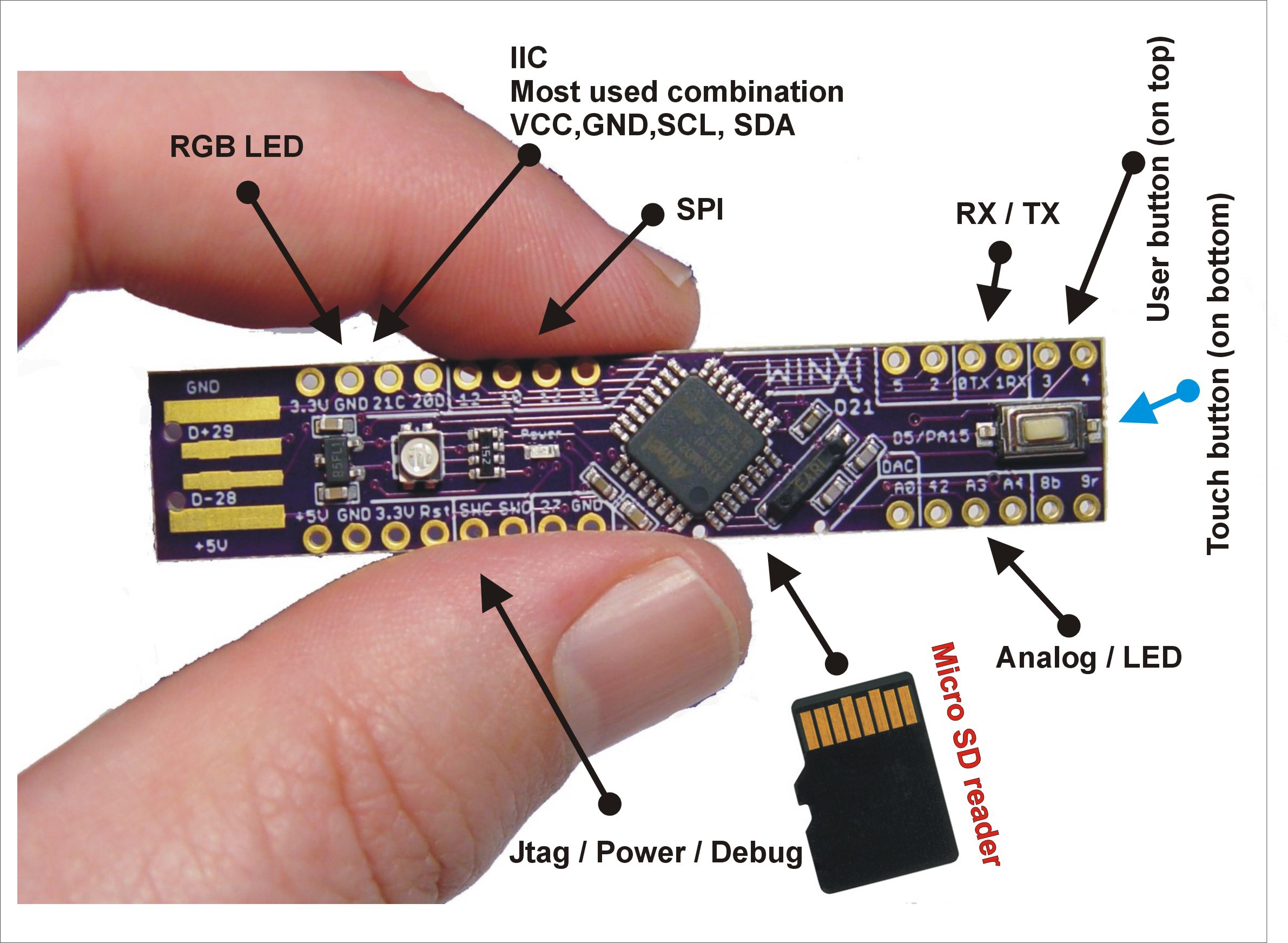
https://hackaday.io/project/10208-winxi-arduino-zero-pro-m0-stick-atsamd21e18And this one which I think is the closest to what you want to do ?
(32 pins chip, 2 layers, usb and basically the size of a nano)
https://hackaday.io/project/6276-sam-d20d21-breakout-boardIt probably would benefit from a few improvements but it's a good start I think ? Especially when author provides eagle files...
-
Have you checked this ?
https://hackaday.io/project/10208-winxi-arduino-zero-pro-m0-stick-atsamd21e18And this one which I think is the closest to what you want to do ?
(32 pins chip, 2 layers, usb and basically the size of a nano)
https://hackaday.io/project/6276-sam-d20d21-breakout-boardIt probably would benefit from a few improvements but it's a good start I think ? Especially when author provides eagle files...
Thank you! Those are great finds. Yes, the second one has fewer parts than the first, and therefore closer to what I want to do.
Also, it's now clear that Sparkfun went through a lot of effort (and resorted to a 4-layer PCB) in order to maintain the "pro mini" style pinout on its board. I'm realizing now that--for present purposes--it's not worth the extra cost and effort of doing that. Instead, just doing a simple "breakout" type mapping, as the second Hackaday project did, is sufficient.
-
i agree with you for 4layers, it's not needed.
personally, i wouldn't go too much minimalist with decoupling, or usb, because it depends on what you connect then to your mainboard.. I see this on lot of boards, not following basic usb specs.. -
Yes that's why I say it needs some improvements.
Most of SAMD2x boards I see use some ferrite beads in addition to a bunch of capacitors. -
Looks as though the second one he didn't even bother with USB, even though he had the pads for it on his board. He did it all through the SWD connector. I'm planning to reduce that 10 pin debug connector to just 4 pins, since that's all my ST-LINK V2 interface has anyway. It should be arriving today:
https://www.amazon.com/gp/product/B0722WMDFQ/ref=oh_aui_detailpage_o00_s00?ie=UTF8&psc=1 -
Now that I think about it, I think I'll make a completely "dumb" breakout board, where it's just every pin of the SAMD21 mapped to a post, and it's only just the SAMD21 chip on the board. Then I can experiment on breadboard and figure out what I want and what works before finally reducing it to a subsequent PCB.
I suppose it makes sense, though, to put the 32.768khz crystal on the board though.
-
@NeverDie it would also make sense to make at least the "basic" decoupling capacitors/pullups/...
You're right. So, I think this will probably be it then: 0_1496760742368_Schematic_for_SAMD21_TQFP32_Pro_Mini _v003.pdf
It's the guts of the sparkfun design, but with just one LED, and minus the usb, and with a 4 pin SWD connection, and the easiest possible mapping of chip pins to external pins.
What do you think?
-
On the other hand, at least during development, it seems a shame to lose the USB connection. I suppose maybe (?) the USB could be pumped through some kind of external 5v to 3.3v level shifter, and then I wouldn't need to put voltage converters on the board itself. It wouldn't any longer meet the official USB spec, but maybe it would work just the same. That in turn would help reduce the size and costs. Never tried that before with USB though, so it's an unknown to me as to whether it would work or not.
-
I can probably make it a bit more compact, but without the USB, this will be the approximate shape of it: 0_1496774768997_SAMD21_TQFP32_Breakout_v003.pdf
-
The whole thing is less than one square inch in size, so I went ahead and ordered the non-usb version from osh-park:
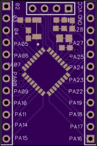
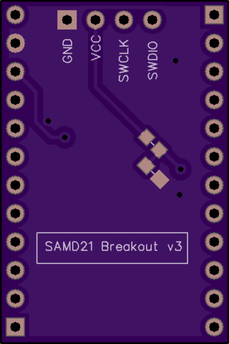
The silkscreen could be better, but it's good enough to test whether or not it's going to fly.
It appears there's plenty of space at the bottom for adding a USB connector, so I guess that will be next....
-
I don't see any decoupling capacitors or ferrite beads on the USB data circuit. According to the schematic ( https://cdn.sparkfun.com/datasheets/Dev/Arduino/Boards/sparkfun-samd21-mini-breakout-v10.pdf), USB_D- and USB_D+ just connect directly to pins PA24 and PA25 on the MCU.
-
What size pads are you guys using for your SAMD21 land pattern? Mine don't look right. The SAMD21 datasheet didn't actually give a land pattern. It just gave the size of the legs, and so I just made up a land pattern that was close to that. Looks too small compared to others that I'm seeing (e.g. on the Hackaday).
@NeverDie said in Minimalist SAMD21 TQFP32 Pro Mini:
What size pads are you guys using for your SAMD21 land pattern? Mine don't look right. The SAMD21 datasheet didn't actually give a land pattern. It just gave the size of the legs, and so I just made up a land pattern that was close to that. Looks too small compared to others that I'm seeing (e.g. on the Hackaday).
Nevermind. I found the answer on page 10 of http://www.atmel.com/Images/Atmel-8826-SEEPROM-PCB-Mounting-Guidelines-Surface-Mount-Packages-ApplicationNote.pdf
-
I don't see any decoupling capacitors or ferrite beads on the USB data circuit. According to the schematic ( https://cdn.sparkfun.com/datasheets/Dev/Arduino/Boards/sparkfun-samd21-mini-breakout-v10.pdf), USB_D- and USB_D+ just connect directly to pins PA24 and PA25 on the MCU.
@NeverDie said in Minimalist SAMD21 TQFP32 Pro Mini:
I don't see any decoupling capacitors or ferrite beads on the USB data circuit. According to the schematic ( https://cdn.sparkfun.com/datasheets/Dev/Arduino/Boards/sparkfun-samd21-mini-breakout-v10.pdf), USB_D- and USB_D+ just connect directly to pins PA24 and PA25 on the MCU.
I saw that on the Adafruit board I think, and on the SenseBender gateway.
-
you should not add decoupling /ferite beads to the D+/D- lines.. At most, add a protection resistor of 30R (or there about) inline, to limit current flow. Also you can add a USB protection circuit with diodes externally..
The ferite bead / capacitors on the sensebender, is between the cable shield, and gnd on the device, to limit EMI on the cable shielding..
-
Just realizing that if I'm going to hand patch the 4 SWD wires onto the board anyway, then I really don't need an SWD block. Consequently, I'm now thinking the Hackaday guy had the right idea with making his entire node the width of a USB connector:
-
Just realizing that if I'm going to hand patch the 4 SWD wires onto the board anyway, then I really don't need an SWD block. Consequently, I'm now thinking the Hackaday guy had the right idea with making his entire node the width of a USB connector: