nRF5 action!
-
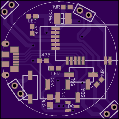
Here's the hardware I developed it on:
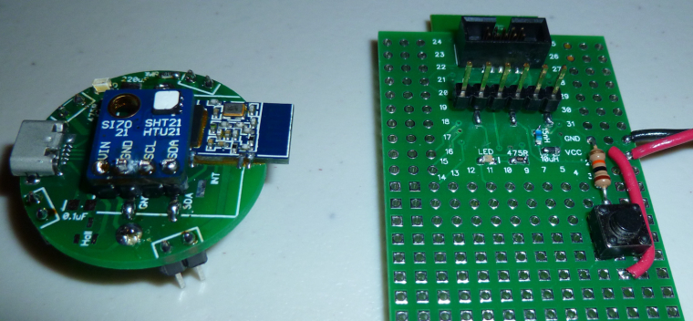
For the nRF52832 (on the right), I literally used a button push to simulate a leak detection. However, for the nRF51822 (on the left), I did use the leak detection pins. I've tried putting it on a flooded surface and, indeed, it does detect water. By that I mean a water leak is enough to wake it up from sleep and trigger a detection event. -
I just now measured the sleep current on the nRF51822 (above), and it is 3.9ua. So, higher than the nRF52822. Go figure.
BTW, I'm using a uCurrent Gold paired to a Fluke 87V for my current measurements, so I think my measurements are probably reasonably accurate (and repeatable by anyone else with similar equipment).
-
@NeverDie Nice stuff! Perhaps you could file a PR and include it as a example in the repo?
@Anticimex said in nRF5 Bluetooth action!:
@NeverDie Nice stuff! Perhaps you could file a PR and include it as a example in the repo?
I think instead of that I'll bake it into an improved demo script for the multisensor node and post it there. So, instead of waking up every 5 seconds to blink an LED, it will instead wake-up every 5 minutes to take a temperature/humidity reading and report it back wirelessly to the gateway. Meanwhile, if it happens to detect a water leak, it will report that the instant it is detected. That will be the practical upshot of the above script, which is a boilerplate for how to quickly respond to interrupts while sleeping and yet still remain miserly with respect to battery consumption.
Or, better yet, I'll do it for the PIR demo code, since it doesn't yet have demo code. Same basic idea.
-
@NeverDie Nice stuff! Perhaps you could file a PR and include it as a example in the repo?
@Anticimex said in nRF5 Bluetooth action!:
@NeverDie Nice stuff! Perhaps you could file a PR and include it as a example in the repo?
I posted an enhanced version of it here as the demo sketch--it includes proper MySensors radio code as well: https://www.openhardware.io/view/499/10-years-wireless-PIR-Sensor-on-just-one-set-of-3-AAs#tabs-source
-
Need your help, guys. I am trying to reprogram a smart socket based on nrf51 module. The schematic is:
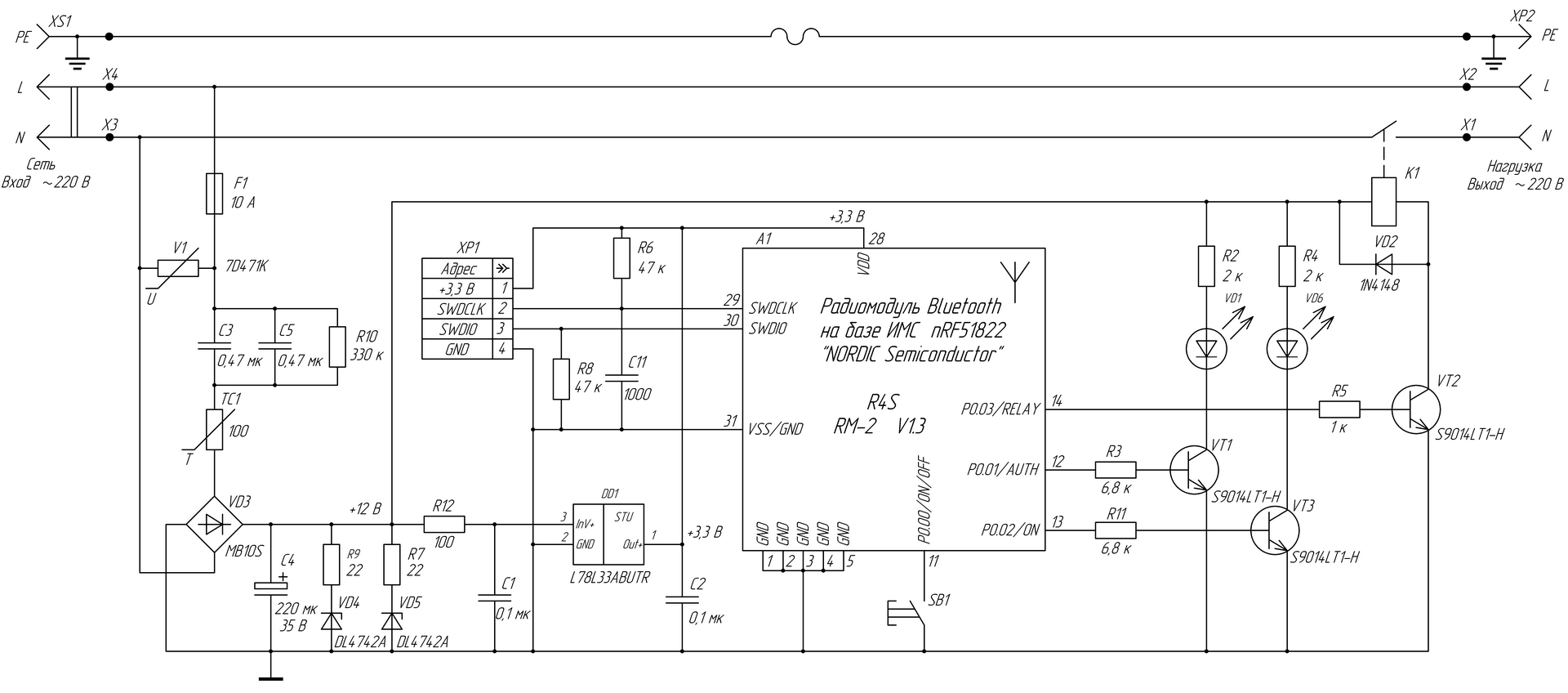
I successfully did it using conventional BT Arduino core (Sandeep's) and I was able to switch the relay on/off.
However, when I tried to use Mysensors ESB5 implementation, the relay just switches On briefly and then immediately Off.
I believe this is because the pin doesn't supply enough current for the transistor to saturate (3.3v/1k=3.3ma).
Questions:
a ) shall I use hwPinMode(PIN, OUTPUT_S0H1)? if yes,
b ) why in non-MySensors sketch a simple pinMode(PIN, OUTPUT) worked?
Does MuSensors implementation overrides Sandeep's definitions so the pin supplies less current? -
Need your help, guys. I am trying to reprogram a smart socket based on nrf51 module. The schematic is:
I successfully did it using conventional BT Arduino core (Sandeep's) and I was able to switch the relay on/off.
However, when I tried to use Mysensors ESB5 implementation, the relay just switches On briefly and then immediately Off.
I believe this is because the pin doesn't supply enough current for the transistor to saturate (3.3v/1k=3.3ma).
Questions:
a ) shall I use hwPinMode(PIN, OUTPUT_S0H1)? if yes,
b ) why in non-MySensors sketch a simple pinMode(PIN, OUTPUT) worked?
Does MuSensors implementation overrides Sandeep's definitions so the pin supplies less current?@Toyman I don't know the answers, but section 20.4.1 GPIO Electrical Specification from the datasheet might give you some insight. What I notice from it is that there's quite a spread between the min and max driver current rating, with no real explanation as to why. So, for that reason, if your target currents are higher than the minimum ratings, perhaps you're better off using an nRF5 pin to control a load switch, which in turn should easily handle your desired currents?
-
@Toyman I don't know the answers, but section 20.4.1 GPIO Electrical Specification from the datasheet might give you some insight. What I notice from it is that there's quite a spread between the min and max driver current rating, with no real explanation as to why. So, for that reason, if your target currents are higher than the minimum ratings, perhaps you're better off using an nRF5 pin to control a load switch, which in turn should easily handle your desired currents?
-
The schematic is given. I just don't understand why it worked with BLE core and why it doesn't with d0016's.
I always thought Mysensors is an extension of vanilla nrf5 arduino core.@Toyman said in nRF5 Bluetooth action!:
The schematic is given. I just don't understand why it worked with BLE core and why it doesn't with d0016's.
I always thought Mysensors is an extension of vanilla nrf5 arduino core.You have to remove the SoftDevice. The EEPROM Emulation, included in MySensors, is incompatible and the radio and RTC interrupt is blocked by the SoftDevice. The system call to disable the SoftDevice is not available in the Arduino port. Here is some example to erase the MCU.
-
@Toyman said in nRF5 Bluetooth action!:
The schematic is given. I just don't understand why it worked with BLE core and why it doesn't with d0016's.
I always thought Mysensors is an extension of vanilla nrf5 arduino core.You have to remove the SoftDevice. The EEPROM Emulation, included in MySensors, is incompatible and the radio and RTC interrupt is blocked by the SoftDevice. The system call to disable the SoftDevice is not available in the Arduino port. Here is some example to erase the MCU.
-
@d00616 everything is working EXCEPT relay control.
So the node is recognized in Domoticz, I can switch it on and off, but the relay just doesn't switch on permanently when I send HIGH to the pin. It switches on and almost immediately off.@Toyman said in nRF5 Bluetooth action!:
@d00616 everything is working EXCEPT relay control.
So the node is recognized in Domoticz, I can switch it on and off, but the relay just doesn't switch on permanently when I send HIGH to the pin. It switches on and almost immediately off.With the extended output mode, you are on the safe side, but I think this isn't the problem. Maybe domoticz sends the off command or there is something in the sketch logic. Please try to switch on the port outside the MySensors logic like in setup() or by the button.
Your design has connected a button to P0.00 and an transistor to P0.01. These pins are for the 32kHz clock. Please check, that you have to choosen the RC oscillator as LFCKL source.
-
I received a battery clip designed to hold two CR2032's in series, but I was surprised to find how much wider it is than a single cell holder:
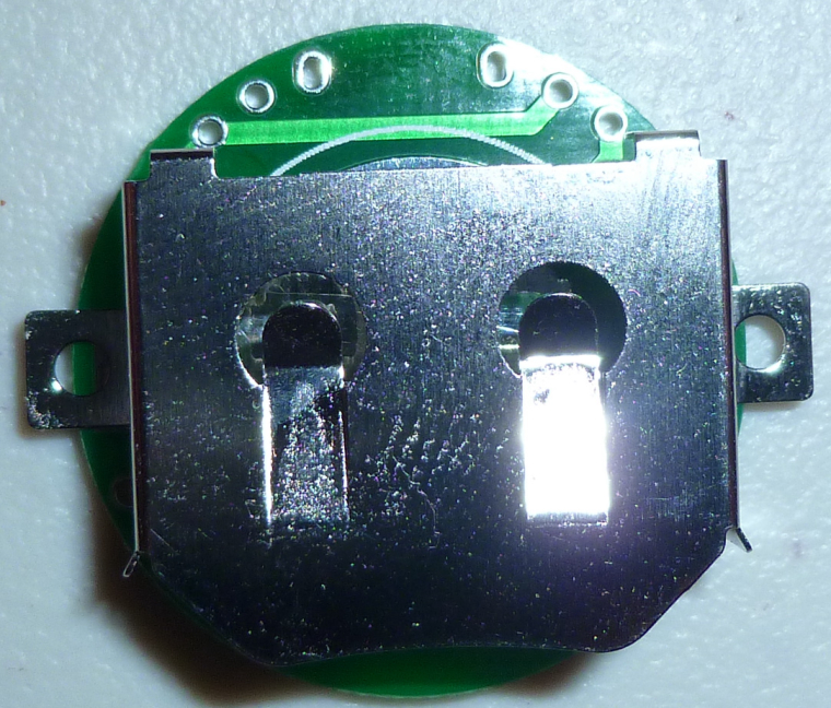
Why? And, is that how they all are?So, at this point, I either need to increase the PCB diameter again, or else go square and hang this clip diagonally.
You may ask, why do this at all? One of the reasons is that the AM612 PIR requires a minimum of 2.7v, and a single CR2032 doesn't leave much headroom, especially given the dippy discharge nature of coincells. I figure two CR2032's in series with a voltage regulator should, in theory, manage the issue a lot better. Indeed, with that in mind, I already have PCB's with the pads for a voltage regulator on them, but I didn't expect the battery clip to be so big.
-
I received a battery clip designed to hold two CR2032's in series, but I was surprised to find how much wider it is than a single cell holder:
Why? And, is that how they all are?So, at this point, I either need to increase the PCB diameter again, or else go square and hang this clip diagonally.
You may ask, why do this at all? One of the reasons is that the AM612 PIR requires a minimum of 2.7v, and a single CR2032 doesn't leave much headroom, especially given the dippy discharge nature of coincells. I figure two CR2032's in series with a voltage regulator should, in theory, manage the issue a lot better. Indeed, with that in mind, I already have PCB's with the pads for a voltage regulator on them, but I didn't expect the battery clip to be so big.
-
I did a quick hack for testing purposes:
With all this extra space, I could probably add the hall sensor back in. I had taken it out so that I'd have the option of adding an extra LED, plus two pushbuttons. -
I found a much better 2x battery clip made by Linx. Even though it's through-hole rather than surface mount, its footprint is much smaller. https://www.mouser.com/Search/ProductDetail.aspx?R=BAT-HLD-001-THMvirtualkey66280000virtualkey712-BAT-HLD-001-THM
Using it, I don't have to enlarge the diameter or go square. I can keep the same size. -
@toyman said in nRF5 Bluetooth action!:
@neverdie frankly, I would revive CR2450 idea. 620mah vs 200mah is HUGE difference
If I can keep the footprint the same (and I don't see why not), I could attach a 2x battery clip for a 2450, and then you'd have the best of both worlds. I have a hunch that finding such a clip, though, won't be easy.
-
@neverdie
maybe check out: https://www.aliexpress.com/item/5pcs-20-0mm-CR2032-2032-Battery-Button-Cell-Holder-Coin-Cell-Retainer-Battery-Holder-Through-hole/32741947070.html?spm=a2g0s.9042311.0.0.E38CWgor if you need 50... :
https://www.aliexpress.com/item/50pcs-20-0mm-CR2032-2032-Battery-Button-Cell-Holder-Coin-Cell-Retainer-Battery-Holder-Through-hole/32739802992.htmlprice wise,, i would say, go for the second one ;)
@omemanti Thanks.
I ordered the Linx from mouser yesterday, though. It uses four smaller pins instead of two larger pins. That actually helps keep the footprint small. Also, Linx has practically identical holders for holding a single CR2032 versus holding two CR2032's. That means I can use a single PCB board and decide which configuration I want. The mouser price is quite reasonable (about 25 cents each).
I did try looking for a holder that can hold two CR2450's in series, but I didn't find any.
-
I received the Linx parts today. I like them more than any other battery holders I've yet seen, because they elevate the sides just a smidge, which eliminates any risk of short-circuiting to nearby through-holes. For instance, the ones from Aliexpress (linked above by Omemtani) don't do that. Nor do any of the other ones I've tried so far.
On Tuesday I should receive PCB's specifically designed to use the Linx holders. I can hardly wait.
-
I just noticed these small and fairly cheap nRF52 modules on Aliexpress:
https://www.aliexpress.com/item/wholesale-Holyiot-TinyBLE-nRF52832-Bluetooth-low-energy-module-BLE-5-0-for-Bluetooth-mesh/32840369737.html?spm=2114.search0204.3.2.eQaXfB&ws_ab_test=searchweb0_0,searchweb201602_4_10152_10065_5000015_10151_10344_10068_10130_10345_10324_10342_10547_10325_10343_51102_10546_10340_10341_10548_10545_5130015_10541_10084_10083_10307_5690015_10539_5080015_10312_10059_10313_10314_10534_100031_10604_10603_10103_10605_10594_5060015_10596_10142_10107,searchweb201603_14,ppcSwitch_4_ppcChannel&algo_expid=f4f4f444-b2af-44da-9380-676cdca3c65f-0&algo_pvid=f4f4f444-b2af-44da-9380-676cdca3c65f&rmStoreLevelAB=0
But how would one solder it? Is solder paste the only option?