nRF5 action!


  • @d00616 have you looked at https://mynewt.apache.org/?


  • Hero Member

    @Toyman said in nRF5 Bluetooth action!:

    @d00616 have you looked at https://mynewt.apache.org/?

    Does it have any worthwhile demo apps running on it?


  • Contest Winner

    @Toyman said in nRF5 Bluetooth action!:

    @d00616 have you looked at https://mynewt.apache.org/

    Yes, I have seen the documentation and some parts of the source code. It's a good project. I like the concepts.


  • Hardware Contributor

    @Toyman said in nRF5 Bluetooth action!:

    @d00616 have you looked at https://mynewt.apache.org/?

    on my side, i tested it. agree with d00616, it's interesting.
    yes there are examples.


  • Hero Member

    How would you all rate the mynewt's stage of development? Pre-alpha? Or, is it already fairly well tested and production ready?


  • Hardware Contributor

    latest release is 1.2.0, it's not prealpha. for production I think, easiest is to read docs and try 😉

    Note it's an OS (which means shared resources etc..), not arduino integrated, nor mysensors compatible actually. If you want to use MySensors, you would need to port the code and check what's in use by the OS etc..

    If I would like to use a RTOS+BLE with NRF5, I would use this one.
    For other mcus, not sure, there are others nice OS.
    Hard to find one fits for all, and not very handy to have x toolchains&libraries to handle (I already have arduino, espressif, apache, TI.. OS&frameworks installed and this can be too much!). And i don't mention rpi/linux stuff..

    That depends on the project.
    But for my HA project, as MySensors targets arduino actually, and I prefer the NRF5 ESB driver than BLE for multiple reasons (security etc), it's easier to stick to arduino environment and I can use all mcus for that in Visual Studio.


  • Hero Member

    How are people here preferring to connect to their nRF5x node for programming/debugging? I had been using a 10-pin IDE boxed connector on the PCB's I was making, but I just recently tried a micro-USB OTG connector (just as a 5-pin connector, not for anything truly USB protocol related), and I find that I like it a lot. For one thing, it's a lot more compact:
    0_1511483028982_usbcon_2.jpg
    0_1511483048204_usbcon_1.jpg

    It does require making an adapter, but once you've made it (once and done), it's easy.

    Any thoughts on this? I'm tentatively leaning toward switching over to it for everything.


  • Hero Member

    The other cool thing is that the side access allows me to make a very compact PIR motion sensor that's still re-programmable:
    0_1511485705122_compact_PIR.jpg
    🙂


  • Hardware Contributor

    @NeverDie I think it's ok only if you keep those only for yourself, and/or make an enclosure hiding this plug.
    Because if you give to someone like a friend and an USB plug is visible one day or another they'll plug it and fry the board with 5V 🙂


  • Hero Member

    Good point. To avoid that as a potential problem then, can anyone suggest a better connector to use?


  • Hero Member

    I suppose if/when OTA updates are developed for the nRF5x's, then the issue would go away. Then you'd only need the connector when first setting it up, and then later work could be uploaded OTA. After the initial setup, one could simply sabotage the USB connector (fill it with epoxy maybe, or perhaps just cut the traces) to prevent the friend from plugging the node into an actual USB charger or the like.


  • Mod

    I'd say to make something with pogo pins if you really need it once


  • @NeverDie check out a product called "TAG-CONNECT". It is perfect for programming. It is used on the Nordic Semiconductor Beacon Reference Design.


  • Contest Winner

    @Jokgi said in nRF5 Bluetooth action!:

    @NeverDie check out a product called "TAG-CONNECT". It is perfect for programming. It is used on the Nordic Semiconductor Beacon Reference Design.

    Thank you. Here is an programmer with this connector: http://aconno.de/acnprog/
    I don't know if this is compatible to the Beacon Reference Design, but its compatible with the nRF52 boards provided by aconno.


  • @d00616 not familiar with the USB interface / tag connect. The ones I have used have the connector type that plugs onto the nRF5x-DK, uLinks, jlink lite, etc. a ten pin Micro Cortex connector to six or ten pin "pogo pin" tag-connect connector. There is also a clip that allows the connector to stay attached for debugging purposes.


  • Hero Member

    A bit off-topic perhaps, but does anyone here happen to know what kind of switch Enocean uses to transduce a button press into the electrical energy needed to send a packet? I'm guessing it's some kind of piezo switch. Can just that transducer part be purchased by itself? I'm wondering whether the same trick can be done using an nRF5...


  • I would stick with cortex 10-pin connector. Mostly because it's (a) standard (b) a cable can be made without soldering by using IDC connectors and a ribbon cable.
    The only downside is height.
    Using USB connector for sometging that's not USB is generally a bad idea as it's not foolproof


  • Is signing soft supported or not yet ?

    The personalizer sketch do not have hash define for the NRF52.


  • Contest Winner

    @ahmedadelhosni pull requests are always welcome.


  • Contest Winner

    @ahmedadelhosni said in nRF5 Bluetooth action!:

    Is signing soft supported or not yet ?
    The personalizer sketch do not have hash define for the NRF52.

    The security personalizer is working with the NRF5X. Random numbers for the Soft Signing are generated with the internal AES hardware, seeded with the hardware number generator. This allows a fast and secure nonce generation.

    At the Moment the NRF5 with Soft Signing is not at the same level like the ATSHA204, because the read back protection is not enabled. If you want to do this, you have to add some code.


  • Hero Member

    What else should I turn-off to save power during sleep?

    Presently, I turn-off these things: the radio, NFC, the high frequency clock, and uarte, Meanwhile, the low frequency clock is working.

    Presently getting a sleep current drain of apprxoimately 2.8 microamps.


  • Hardware Contributor

    @NeverDie said in nRF5 Bluetooth action!:

    What else should I turn-off to save power during sleep?

    Presently, I turn-off these things: the radio, NFC, the high frequency clock, and uarte, Meanwhile, the low frequency clock is working.

    Presently getting a sleep current drain of apprxoimately 2.8 microamps.

    Which chip are you talking about ?


  • Hero Member

    nRF52832. I'm guessing the same will apply to the nRF51822, except for the NFC (which the nRF51822 doesn't have).


  • Hero Member

    I should probably add that the 2.8ua is with the RTC and LPCOMP running. So, maybe it's already as low as it can go, I don't know. Just wondering if there are any other obvious suspects I should try turning off. I'll try i2C and SPI to see if it makes a difference... Not sure, but maybe SPI gets initialized through the header file without my even being aware of it.


  • Hero Member

    Well, it could be within the bounds of measurement error, but it appears that dropping I2c and SPI has reduced the drain to 2.6ua.


  • Contest Winner

    @NeverDie said in nRF5 Bluetooth action!:

    Well, it could be within the bounds of measurement error, but it appears that dropping I2c and SPI has reduced the drain to 2.6ua.

    Is I2C or SPI used somewhere in your code?


  • Hero Member

    @d00616 said in nRF5 Bluetooth action!:

    @NeverDie said in nRF5 Bluetooth action!:

    Well, it could be within the bounds of measurement error, but it appears that dropping I2c and SPI has reduced the drain to 2.6ua.

    Is I2C or SPI used somewhere in your code?

    Not in the current test code that I'm running.


  • Contest Winner

    @NeverDie said in nRF5 Bluetooth action!:

    Not in the current test code that I'm running.

    Interesting. The SPI is rated with <1µA idle current. TWI has no idle current in the datasheet.


  • Hero Member

    @d00616 Well, I suppose that's consistent with what I'm seeing, isn't it? i.e. not much effect.


  • Hero Member

    So far, UARTE is the biggest offender. Turning off and disabling that saves a lot of current.


  • Hero Member

    So, here is code which works! Many thanks to @d00616 and others for their helpful comments above.

    To keep from distracting, I stripped out the radio code, but you can easily insert your favorite brand of that.

    Basically, the sketch blinks an LED very briefly once every 5 seconds. Between blinks, it sleeps. However, if a leak is detected (which is equivalent to a button push), it wakes up immediately and blinks a lot. It runs on both nRF52832 and nRF51822. The sleep current is ~2.6ua on an nRF52832. To get sleep current that low, it is using the Low Power Comparator (LPCOMP) to watch for a change on the leak detector pin while the CPU sleeps.

    I haven't yet measured the sleep current consumption on an nRF51822, but I expect it would be something comparable.

    //This sketch is applicable to Coincell Multisensor nRF51822, version 10
    
    #define MY_CORE_ONLY
    
    
    #define IS_NRF51  //true iff the target is an nRF51.  If an nRF52, then comment this line out!
    
    #define I2C_INTERRUPT_PIN 3
    #define LEAK_DETECTION_PIN 2
    
    #include <nrf.h>
    #include <MySensors.h>
    
    volatile bool button_pressed=false;
    
    void blinkityBlink(uint8_t pulses, uint8_t repetitions) {
      for (int x=0;x<repetitions;x++) {
        for (int i=0;i<pulses;i++) {
          digitalWrite(LED_BUILTIN,HIGH);
          wait(20);
          digitalWrite(LED_BUILTIN,LOW);
          wait(100);
        }    
          wait(500);
      }
    }
    
    void disableNfc() {  //only applied to nRF52
    
    #ifndef IS_NRF51
      //Make pins 9 and 10 usable as GPIO pins.
      NRF_NFCT->TASKS_DISABLE=1;  //disable NFC
      NRF_NVMC->CONFIG=1;  // Write enable the UICR
      NRF_UICR->NFCPINS=0; //Make pins 9 and 10 usable as GPIO pins.
      NRF_NVMC->CONFIG=0;  // Put the UICR back into read-only mode.
    #endif
    }
    
    
    void turnOffRadio() {
      NRF_RADIO->TASKS_DISABLE=1;
      while (!(NRF_RADIO->EVENTS_DISABLED)) {}  //until radio is confirmed disabled
    }
    
    void turnOffUarte0() {
    #ifndef IS_NRF51  
      NRF_UARTE0->TASKS_STOPRX = 1;
      NRF_UARTE0->TASKS_STOPTX = 1;
      NRF_UARTE0->TASKS_SUSPEND = 1;
      NRF_UARTE0->ENABLE=0;  //disable UART0
      while (NRF_UARTE0->ENABLE!=0) {};  //wait until UART0 is confirmed disabled.
    #endif
    
    #ifdef IS_NRF51
      NRF_UART0->TASKS_STOPRX = 1;
      NRF_UART0->TASKS_STOPTX = 1;
      NRF_UART0->TASKS_SUSPEND = 1;
      NRF_UART0->ENABLE=0;  //disable UART0
      while (NRF_UART0->ENABLE!=0) {};  //wait until UART0 is confirmed disabled.
    #endif
    }
    
    void turnOffAdc() {
    #ifndef IS_NRF51
      if (NRF_SAADC->ENABLE) { //if enabled, then disable the SAADC
        NRF_SAADC->TASKS_STOP=1;
        while (NRF_SAADC->EVENTS_STOPPED) {} //wait until stopping of SAADC is confirmed
        NRF_SAADC->ENABLE=0;  //disable the SAADC
        while (NRF_SAADC->ENABLE) {} //wait until the disable is confirmed
      }
    #endif
    }
    
    
    void turnOffHighFrequencyClock() {
        NRF_CLOCK->TASKS_HFCLKSTOP = 1;
        while ((NRF_CLOCK->HFCLKSTAT) & 0x0100) {}  //wait as long as HF clock is still running.
    }
    
    
    void mySleepPrepare()
    {
      turnOffHighFrequencyClock();
      turnOffRadio();
      turnOffUarte0();
    }
     
    
    void activateLpComp() {
      //NRF_LPCOMP->PSEL=1; // monitor AIN1 (pin P0.03 on nRF52832 test board).
      //while (!(NRF_LPCOMP->PSEL==1)) {} //wait until confirmed
      NRF_LPCOMP->PSEL=3; // monitor AIN3 (pin P0.02 on nRF51822 for coincell_multisensor_v10)
      while (!(NRF_LPCOMP->PSEL==3)) {} //wait until confirmed
      NRF_LPCOMP->REFSEL=1;  // choose 1/4 VDD as the reference voltage
      while (!(NRF_LPCOMP->REFSEL==1)) {} //wait until confirmed
      NRF_LPCOMP->ANADETECT=1;  //detect UP events.
      while (NRF_LPCOMP->ANADETECT!=1) {} //wait until confirmed
      NRF_LPCOMP->INTENSET=B0100;  //Enable interrupt for UP event
      while (!(NRF_LPCOMP->INTENSET==B0100)) {} //wait until confirmed
      NRF_LPCOMP->ENABLE=1;  //Enable LPCOMP
      while (!(NRF_LPCOMP->ENABLE==1)) {} //wait until confirmed
      NRF_LPCOMP->TASKS_START=1;  //start the LPCOMP
      while (!(NRF_LPCOMP->EVENTS_READY)) {}  //wait until ready
      
      NVIC_SetPriority(LPCOMP_IRQn, 15);
      NVIC_ClearPendingIRQ(LPCOMP_IRQn);
      NVIC_EnableIRQ(LPCOMP_IRQn);
    }
    
    void suspendLpComp() { //suspend getting more interrupts from LPCOMP before the first interrupt can be handled
      if ((NRF_LPCOMP->ENABLE) && (NRF_LPCOMP->EVENTS_READY)) {  //if LPCOMP is enabled
        NRF_LPCOMP->INTENCLR=B0100;  //disable interrupt from LPCOMP
        while (NRF_LPCOMP->INTENCLR==B0100) {} //wait until confirmed
      }
    }
    
    void resumeLpComp() { //suspend getting interrupts from LPCOMP
      NRF_LPCOMP->INTENSET=B0100;  //Enable interrupt for UP event
      while (!(NRF_LPCOMP->INTENSET==B0100)) {} //wait until confirmed
    }
    
    void setup() {
      hwInit();
      hwPinMode(LED_BUILTIN,OUTPUT_D0H1);
      disableNfc();
      turnOffAdc();
      activateLpComp();
      blinkityBlink(2,1);  //Signify end of setup with two quick pulses.
      mySleepPrepare();
      button_pressed=false;
    }
    
    
    void loop() {
    
      sleep(5000);  //sleep for 5 seconds.
      mySleepPrepare();  //An ounce of prevention: Turn-off HF clock, etc, ASAP to save power, just in case the library's sleep() routine resumed them.
      if (button_pressed) {   //if a leak is detected
        suspendLpComp(); //suspend LPCOMP to prevent multiple interrupts
        blinkityBlink(10,3);  //blink a lot to show that a leak was detected.
        button_pressed=false;  //Clear the semaphore
        NRF_LPCOMP->EVENTS_UP=0;  //Clear the semaphore
        resumeLpComp();  //operations of LPCOMP were suspended after detecting the LPCOMP iterrupt
      }
      else {
        blinkityBlink(1,1);  //otherwise, just one short blink to indicate the wakeup was scheduled by the RTC
      }
    }
    
    
    // * Reset events and read back on nRF52
    //* http://infocenter.nordicsemi.com/pdf/nRF52_Series_Migration_v1.0.pdf
     
    #if __CORTEX_M == 0x04
    #define NRF5_RESET_EVENT(event)                                                 \
            event = 0;                                                                   \
            (void)event
    #else
    #define NRF5_RESET_EVENT(event) event = 0
    #endif
    
    
    // This must be in one line
    extern "C" { void LPCOMP_IRQHandler(void) {button_pressed=true; NRF5_RESET_EVENT(NRF_LPCOMP->EVENTS_UP); NRF_LPCOMP->EVENTS_UP=0; MY_HW_RTC->CC[0]=(MY_HW_RTC->COUNTER+2);}}
    

  • Contest Winner

    @NeverDie Nice stuff! Perhaps you could file a PR and include it as a example in the repo?


  • Hero Member

    Here's the hardware I developed it on:
    0_1512074240032_hardware.jpg
    For the nRF52832 (on the right), I literally used a button push to simulate a leak detection. However, for the nRF51822 (on the left), I did use the leak detection pins. I've tried putting it on a flooded surface and, indeed, it does detect water. By that I mean a water leak is enough to wake it up from sleep and trigger a detection event.


  • Hero Member

    I just now measured the sleep current on the nRF51822 (above), and it is 3.9ua. So, higher than the nRF52822. Go figure.

    BTW, I'm using a uCurrent Gold paired to a Fluke 87V for my current measurements, so I think my measurements are probably reasonably accurate (and repeatable by anyone else with similar equipment).


  • Hero Member

    @Anticimex said in nRF5 Bluetooth action!:

    @NeverDie Nice stuff! Perhaps you could file a PR and include it as a example in the repo?

    I think instead of that I'll bake it into an improved demo script for the multisensor node and post it there. So, instead of waking up every 5 seconds to blink an LED, it will instead wake-up every 5 minutes to take a temperature/humidity reading and report it back wirelessly to the gateway. Meanwhile, if it happens to detect a water leak, it will report that the instant it is detected. That will be the practical upshot of the above script, which is a boilerplate for how to quickly respond to interrupts while sleeping and yet still remain miserly with respect to battery consumption.

    Or, better yet, I'll do it for the PIR demo code, since it doesn't yet have demo code. Same basic idea.


  • Hero Member

    @Anticimex said in nRF5 Bluetooth action!:

    @NeverDie Nice stuff! Perhaps you could file a PR and include it as a example in the repo?

    I posted an enhanced version of it here as the demo sketch--it includes proper MySensors radio code as well: https://www.openhardware.io/view/499/10-years-wireless-PIR-Sensor-on-just-one-set-of-3-AAs#tabs-source


  • Need your help, guys. I am trying to reprogram a smart socket based on nrf51 module. The schematic is:
    alt text
    I successfully did it using conventional BT Arduino core (Sandeep's) and I was able to switch the relay on/off.
    However, when I tried to use Mysensors ESB5 implementation, the relay just switches On briefly and then immediately Off.
    I believe this is because the pin doesn't supply enough current for the transistor to saturate (3.3v/1k=3.3ma).
    Questions:
    a ) shall I use hwPinMode(PIN, OUTPUT_S0H1)? if yes,
    b ) why in non-MySensors sketch a simple pinMode(PIN, OUTPUT) worked?
    Does MuSensors implementation overrides Sandeep's definitions so the pin supplies less current?


  • Hero Member

    @Toyman I don't know the answers, but section 20.4.1 GPIO Electrical Specification from the datasheet might give you some insight. What I notice from it is that there's quite a spread between the min and max driver current rating, with no real explanation as to why. So, for that reason, if your target currents are higher than the minimum ratings, perhaps you're better off using an nRF5 pin to control a load switch, which in turn should easily handle your desired currents?


  • The schematic is given. I just don't understand why it worked with BLE core and why it doesn't with d0016's.
    I always thought Mysensors is an extension of vanilla nrf5 arduino core.


  • Contest Winner

    @Toyman said in nRF5 Bluetooth action!:

    The schematic is given. I just don't understand why it worked with BLE core and why it doesn't with d0016's.
    I always thought Mysensors is an extension of vanilla nrf5 arduino core.

    You have to remove the SoftDevice. The EEPROM Emulation, included in MySensors, is incompatible and the radio and RTC interrupt is blocked by the SoftDevice. The system call to disable the SoftDevice is not available in the Arduino port. Here is some example to erase the MCU.


  • @d00616 everything is working EXCEPT relay control.
    So the node is recognized in Domoticz, I can switch it on and off, but the relay just doesn't switch on permanently when I send HIGH to the pin. It switches on and almost immediately off.


  • Contest Winner

    @Toyman said in nRF5 Bluetooth action!:

    @d00616 everything is working EXCEPT relay control.
    So the node is recognized in Domoticz, I can switch it on and off, but the relay just doesn't switch on permanently when I send HIGH to the pin. It switches on and almost immediately off.

    With the extended output mode, you are on the safe side, but I think this isn't the problem. Maybe domoticz sends the off command or there is something in the sketch logic. Please try to switch on the port outside the MySensors logic like in setup() or by the button.

    Your design has connected a button to P0.00 and an transistor to P0.01. These pins are for the 32kHz clock. Please check, that you have to choosen the RC oscillator as LFCKL source.


  • Hero Member

    I received a battery clip designed to hold two CR2032's in series, but I was surprised to find how much wider it is than a single cell holder:
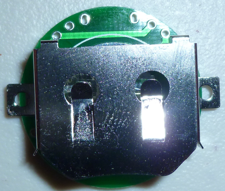
    0_1512523048051_battery_clip.jpg
    Why? And, is that how they all are?

    So, at this point, I either need to increase the PCB diameter again, or else go square and hang this clip diagonally.

    You may ask, why do this at all? One of the reasons is that the AM612 PIR requires a minimum of 2.7v, and a single CR2032 doesn't leave much headroom, especially given the dippy discharge nature of coincells. I figure two CR2032's in series with a voltage regulator should, in theory, manage the issue a lot better. Indeed, with that in mind, I already have PCB's with the pads for a voltage regulator on them, but I didn't expect the battery clip to be so big.


  • @neverdie said in nRF5 Bluetooth action!:

    else go square

    if you ask me, go this way given the BT module itself is already beyond the circular footprint


  • @neverdie frankly, I would revive CR2450 idea. 620mah vs 200mah is HUGE difference


  • Hero Member

    I did a quick hack for testing purposes:
    0_1512574770015_v20_2.png
    0_1512574776678_v20_1.png
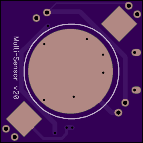
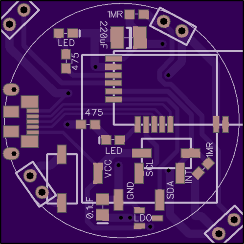
    With all this extra space, I could probably add the hall sensor back in. I had taken it out so that I'd have the option of adding an extra LED, plus two pushbuttons.


  • Hero Member

    I found a much better 2x battery clip made by Linx. Even though it's through-hole rather than surface mount, its footprint is much smaller. https://www.mouser.com/Search/ProductDetail.aspx?R=BAT-HLD-001-THMvirtualkey66280000virtualkey712-BAT-HLD-001-THM
    Using it, I don't have to enlarge the diameter or go square. I can keep the same size.


  • Hero Member

    @toyman said in nRF5 Bluetooth action!:

    @neverdie frankly, I would revive CR2450 idea. 620mah vs 200mah is HUGE difference

    If I can keep the footprint the same (and I don't see why not), I could attach a 2x battery clip for a 2450, and then you'd have the best of both worlds. I have a hunch that finding such a clip, though, won't be easy.


  • Hero Member

    @omemanti Thanks.

    I ordered the Linx from mouser yesterday, though. It uses four smaller pins instead of two larger pins. That actually helps keep the footprint small. Also, Linx has practically identical holders for holding a single CR2032 versus holding two CR2032's. That means I can use a single PCB board and decide which configuration I want. The mouser price is quite reasonable (about 25 cents each).

    I did try looking for a holder that can hold two CR2450's in series, but I didn't find any.


  • Hero Member

    I received the Linx parts today. I like them more than any other battery holders I've yet seen, because they elevate the sides just a smidge, which eliminates any risk of short-circuiting to nearby through-holes. For instance, the ones from Aliexpress (linked above by Omemtani) don't do that. Nor do any of the other ones I've tried so far.

    On Tuesday I should receive PCB's specifically designed to use the Linx holders. I can hardly wait.


  • Hero Member


  • Hero Member

    Here's one for the blooper reel:
    0_1512843096871_blooper.jpg
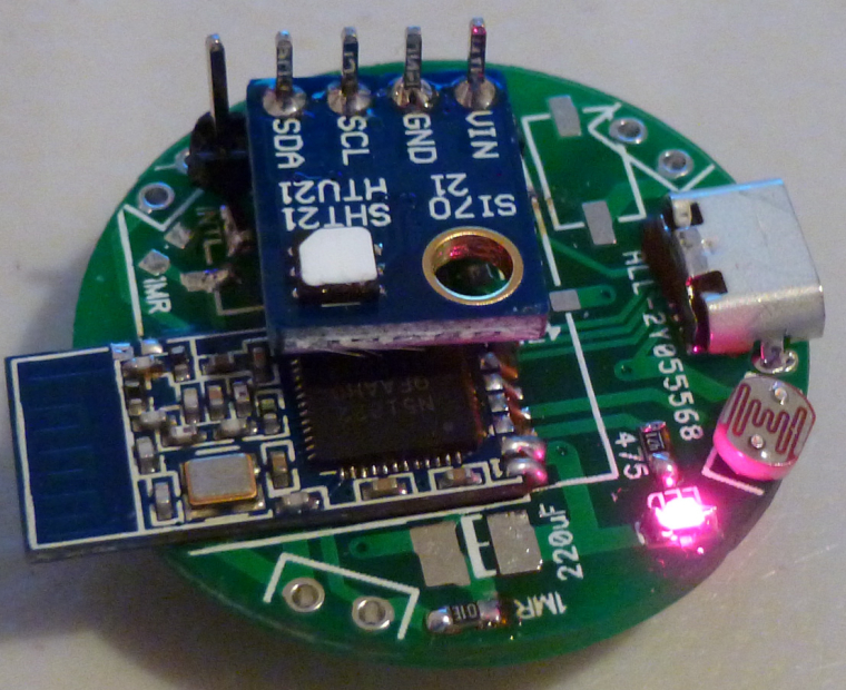
    I blithely put the photoresistor in one of the vacant leak detection slots. Of course, in retrospect, it's an obvious mistake: too close to the LED. So, when the LED lights, the photoresistor thinks it's suddenly bright out. 😆


  • Hardware Contributor

    @neverdie said in nRF5 Bluetooth action!:

    I just noticed these small and fairly cheap nRF52 modules on Aliexpress:
    But how would one solder it? Is solder paste the only option?

    I have bought two to check the range but I don't have very high expectations about that 😄
    For soldering it should work the same way than with qfn chips:

    • put a bit of solder on each pad of the module, then use solder wick to remove excess so it's just lightly tinned
    • put a bit of solder on PCB pads
    • put chip in place, then heat up with hot air gun

    Here as it's a module the hot air might unsolder some components, so using regular iron, flux and a bit oversized pads (so you can heat them up with soldering iron) should do the trick. I will try and tell you the result.


  • @nca78 "At first I was afraid, I was petrified" :-), but then I relialized that if "recepting" pads are long enough even plain soldering iron will do.
    The solder will just flow under the module provided module pads are pretinned Ias you recommended)


  • Hero Member

    @neverdie said in nRF5 Bluetooth action!:

    I received the Linx parts today. I like them more than any other battery holders I've yet seen, because they elevate the sides just a smidge, which eliminates any risk of short-circuiting to nearby through-holes. For instance, the ones from Aliexpress (linked above by Omemtani) don't do that. Nor do any of the other ones I've tried so far.

    On Tuesday I should receive PCB's specifically designed to use the Linx holders. I can hardly wait.

    I received the PCB's a day early. Unfortunately, it's almost total fiction to say that the Linx holder is designed to hold two CR2032's. Instead, it can hold one CR2032 comfortably, or, with finessing, it can hold two CR2025's. With extreme finessing I did get it to hold two CR2032's, but it will be touch-and-go as to whether the solder joints will hold long-term under the strain. Aside from the small footprint, I'm not happy with it. 😞


  • Hero Member

    I guess for now, until something better can be found, I'll simply make do with either 1x CR2032 (240mah) or 2x CR2016 (effectively 100mah).


  • Hero Member

    Here's my latest remote control:
    0_1513208157582_remotec_1.jpg
    0_1513208168355_remotec_2.jpg

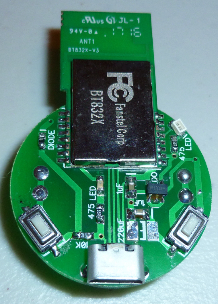
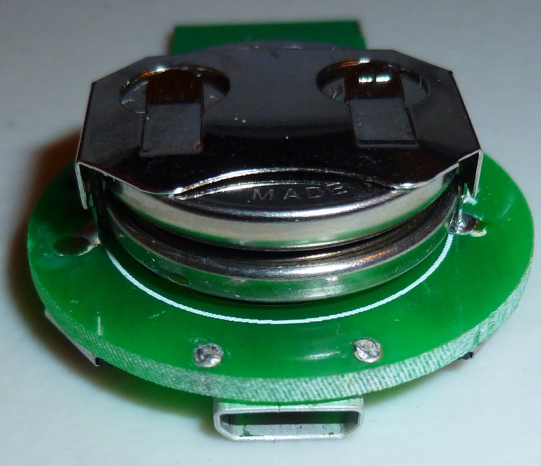
    It has a pa-lna nRF52832 which can draw up to 250ma during Tx. It's powered by two CR2032's but draws absolutely zero current unless one of the buttons is pressed.

    If powered through the connector, however, it can run continuously, without either button being pressed. In that case, it could also serve as a transceiver, sending serial output over the connector.

    It's small and has a nice feel to it. I'm happy with it. 🙂


  • Hero Member

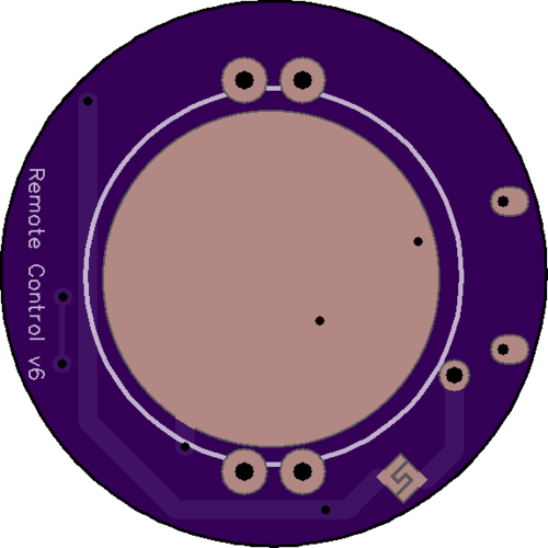
    In the next version I'm going to use a somewhat unusual shaped solder jumper, in case I want to use just a single coin cell battery (not two) and therefore bypass the LDO (well, not install an LDO at all).
    0_1513280257531_solder_jumper2.png


  • @NeverDie I'm thinking about making the jump from NRF24s and RFM69s to the NRF5 eco system. I see you have tried quite a few different modules. If you had to pick now, would you go with the Fanstel BT832X for a gateway and BT832 for most modules?


  • Hero Member

    @nagelc said in nRF5 Bluetooth action!:

    @NeverDie I'm thinking about making the jump from NRF24s and RFM69s to the NRF5 eco system. I see you have tried quite a few different modules. If you had to pick now, would you go with the Fanstel BT832X for a gateway and BT832 for most modules?

    Yes. If cost and space were no issue, I'd probably use the BT832X on everything, because it also has the best antenna. For nRF52's, for what I'm doing I like Fanstel's stuff the best. If I needed a module with more exposed pins, then the EByte would be my choice. But nothing I'm doing requires that many exposed pins, and I think the Fanstel will likely be drop-in upgradeable to the final nRF52840 modules when final silicon for that becomes available. Of course, there's no guarantee of that, but it seems very likely.

    Also important, at least to me, is that the Fanstel modules have FCC approval, and being based in the US, I don't think they're lying about it (unlike random stuff from China).

    That said, the nRF51822-04's are a lot of fun, because they're small and relatively cheap.


  • Great. I have some on order. Can't wait go start playing around with them.


  • Hero Member

    @nagelc said in nRF5 Bluetooth action!:

    Great. I have some on order. Can't wait go start playing around with them.

    Great! I invite you to start making posts to this thread when you do, as fresh perspectives are always welcome.


  • Hello, I want to build battery powered modules (with sleep). I found on Ebay NRF51822 round module with case (https://www.ebay.com/itm/hello/112650665753) - only $6.50 with shipping. Is this module is good choice? Any pitfalls?
    I planning to use water leak sensor, BME280 (I2C), ds18b20(1-wire), maybe MH-Z19 later.
    I don't have enough experience, I have only used ESP8266 NodeMcu V3 and Arduino before.
    I can see one I2C (for programator and sensors?) and one GPIO as button for water leak (right?) + LED pin. Does this module have more pins? Shall I connect to chip legs to obtain more pins (GPIO) (does I need to connect resistors?) for 1-wire or better use some sort of I2C GPIO expander?


  • Hero Member

    @alexey-strelnikov
    Looks nice, but any hardware mods and it probably won't fit the case anymore.


  • Hardware Contributor

    @alexey-strelnikov I have one and there are pads to program it but nothing more, it's not really a "module" but a Bluetooth beacon, the only 2 I/Os available are those from the button and the led, there's a footprint for an accelerometer also but the pads are too tiny to solder any wire.

    If you're planning to use other sensors don't buy that one. It's great as a button sensor but any other use will need soldering to LGA-sized pads...


  • Hardware Contributor

    I received the "holyiot" modules and they are really, really tiny. 2 attached together are exactly the same size than the 51822-04 module. WL-CSP package is very impressive: small, very thin and with a cool shinny surface.
    This module has inductors for DC/DC mode, and pins .00 and .01 are mapped so it's possible to add low frequency crystal for Bluetooth mode.
    0_1513949915111_IMAG2106~2.jpg


  • Hero Member

    @nca78

    Nice!

    I'll be very interested to know how the range compares. At least so far, in my own comparisons, smaller has meant less range. Not necessarily a deal killer though, as you only need range that's "good enough," and you can compensate with a better antenna on the gateway.


  • Hardware Contributor

    @neverdie said in nRF5 Bluetooth action!:

    @nca78

    Nice!

    I'll be very interested to know how the range compares. At least so far, in my own comparisons, smaller has meant less range. Not necessarily a deal killer though, as you only need range that's "good enough," and you can compensate with a better antenna on the gateway.

    Yes I'll try to test next week to have an idea of the range, if it's "good enough" to be usable at least with a central pa/lna gateway or if it's better to stick with bigger PCB antennas.
    nrf51822-04 is small enough but this one has a better chip and 11 I/Os available, that's precious for a multisensor board.


  • Hero Member

    @nca78 said in nRF5 Bluetooth action!:

    nrf51822-04

    What I've noticed is that Rx range was much more compromised with a reduction in size than the Tx range is. Or, to put it differently, Tx range isn't as dramatically compromised. That's potentially good news for a sensor, which may Tx only anyway (i.e. "passive" in the mysensors jargon). But even if it does Rx, your gateway can be much more powerful on its Tx. So, it potentially works out rather nicely, if you know what I mean.


  • Just received my Fanstell modules. Yikes! 1.1mm pin pitch didn't look that small in the pictures. Do you solder these by hand? I thought my soldering skills were getting pretty good, but I can see I'm going to have to up my game.


  • Hero Member

    @nagelc Yes, I solder it by hand. It's easier than it looks. Just use a narrow tip and maybe extra flux if you need it.


  • Hero Member

    Here's my latest gateway sheild for the Wemos D1 Mini:
    0_1514064152895_latest_gateway.jpg

    In the interest of both belt and suspenders, I gave it its own 300ma LDO so that it won't be competing with the Wemos D1 Mini for current. Earlier measurements of this Fanstel ldo-pa nRF52832 shows that it can draw up to 250ma.

    It's designed to work well with ESP-LINK, which can also be used to remotely reset the nRF52832 if that's ever needed. Presently, I'm using ESP-LINK's built-in MQTT to send MQTT to a Mosquito MQTT broker. This offloads that task from the nRF52832, which just inputs/outputs serial.

    By the way, I soldered the entire thing using a wide chisel point solder tip, so it turns out you don't really need a narrow solder tip after all. I do use Rosin flux, though, and it does a great job. The only inconvenience is that the excess Rosin flux should be cleaned off afterward, but, meh, I don't find that to be much of a bother.


  • Hero Member

    @nca78 said in nRF5 Bluetooth action!:

    @neverdie said in nRF5 Bluetooth action!:

    @nca78

    Nice!

    I'll be very interested to know how the range compares. At least so far, in my own comparisons, smaller has meant less range. Not necessarily a deal killer though, as you only need range that's "good enough," and you can compensate with a better antenna on the gateway.

    Yes I'll try to test next week to have an idea of the range, if it's "good enough" to be usable at least with a central pa/lna gateway or if it's better to stick with bigger PCB antennas.
    nrf51822-04 is small enough but this one has a better chip and 11 I/Os available, that's precious for a multisensor board.

    Any update?

    Also, what is the size of the pads? The only info I've found is what appears on the aliexpress website, which only seems to express the distance (center to center) between the pads. I just received some of these modules, so I'd like to maybe do a prototype PCB using my CNC machine. 😉

    BTW, I notice that the price went up from $3.20/module to $4/module. 😞 And something tells me it will probably go higher still.


  • Hardware Contributor

    @neverdie said in nRF5 Bluetooth action!:

    @nca78 said in nRF5 Bluetooth action!:

    @neverdie said in nRF5 Bluetooth action!:

    @nca78

    Nice!

    I'll be very interested to know how the range compares. At least so far, in my own comparisons, smaller has meant less range. Not necessarily a deal killer though, as you only need range that's "good enough," and you can compensate with a better antenna on the gateway.

    Yes I'll try to test next week to have an idea of the range, if it's "good enough" to be usable at least with a central pa/lna gateway or if it's better to stick with bigger PCB antennas.
    nrf51822-04 is small enough but this one has a better chip and 11 I/Os available, that's precious for a multisensor board.

    Any update?

    Also, what is the size of the pads? The only info I've found is what appears on the aliexpress website, which only seems to express the distance (center to center) between the pads. I just received some of these modules, so I'd like to maybe do a prototype PCB using my CNC machine. 😉

    BTW, I notice that the price went up from $3.20/module to $4/module. 😞 And something tells me it will probably go higher still.

    Sorry I was busy with other things. Now my switch seems to work I will quickly finish other atmega projects and make the switch to nrf5x.
    For pad sizes, I believe from the pictures below it's 1mm width (grid size is obviously 0.5mm)
    0_1515471216483_16bdfa3e-0236-4b92-9707-35859a11802c-image.png


  • @nca78 do you move your fantastic Nmodules to nrf5 platform?


  • Hardware Contributor

    @toyman said in nRF5 Bluetooth action!:

    @nca78 do you move your fantastic Nmodules to nrf5 platform?

    Probably, and I will switch to MYSX connector too.


  • Hero Member

    I was just about to make a test board using my CNC when out of the blue my CNC died during setup. So, I did this board instead and will have it fabbed:
    0_1515524108208_HolyIOT_top_v001.png
    0_1515524118988_HolyIOT_bottom_v001.png


  • Hardware Contributor

    @neverdie for a test board why are you not using standard headers and mapping all pins available ?


  • Hero Member

    @nca78 Because originally I was going to do the board on my CNC (that is, before my CNC dropped dead on me), and I wanted to make it as easy as possible for the CNC to succeed. Also, for testing purposes, I'm most interested in how well it sends/receives, and I don't need many pins to test that. Also, soldering this module may be tricky, so I wanted only the minimum number of pins in case soldering it proves to be difficult.


  • Hero Member

    Just received these tiny NRF51822 devices and would like to turn them in to MySensors 1 button scencontroller.
    Where should I start?

    1. I guess I will need some kind of USB adapter ti program them. Think I read somewhere about JLink. Would this do?

    0_1515562170867_20180110_071948.jpg


  • Hardware Contributor

    @korttoma did you check here ?
    https://forum.mysensors.org/topic/6705/mysensors-nrf5-platform

    For programming the best solution is probably the NRF52 DK, it's not very expensive (30€) and you avoid all the problems related to license of the fake JLINKs (and bricking of the device if you happen to accept the invitation to update the outdated firmware on it), as it includes official licence for programming all nrf5 chips.
    https://www.arrow.com/en/products/nrf52-dk/nordic-semiconductor


  • Hi,
    Working without problem with mysensors, I use STLink v2 from Aliexpress. LED and Button are mapped on pins 28 and 29 🙂

    0_1515563097508_IMG-0324.JPG


  • Hero Member

    @mika 👍

    Now I feel stupid ordering the NRF52 DK for 28€. Well atleast I don't need to worry about bricking any devices.
    Do you have an example sketch for the device you can share?
    Is it possible to somehow monitor the battery status?


  • Hero Member

    @korttoma said in nRF5 Bluetooth action!:

    Is it possible to somehow monitor the battery status?

    One of @d00616 's demo sketches allows you to read the voltage that's powering the nRF5. Assuming there is no booster involved on this device (seems unlikely), that would be the same as the battery voltage.


  • @korttoma do you have an Aliexpress link to them?


  • Hero Member

    @toyman sure do LINK


  • @korttoma thx. Do they have a CR2032 slot? Sorry, it's not clear from the pictures


  • Hero Member

    @toyman yes


  • Hero Member

    It would probably do well as a "one button scene controller," but is it good for anything else I wonder?


  • Hero Member

    @neverdie does not seem to be any easy way to get access to any of the pins on the board but who does not need a bunch of "one button scene controllers"?


  • Hardware Contributor

    I was tempted to try adding the missing accelerometer too, but in the end it's easier and cheaper to make a board with the 2$ module.


  • Hero Member

    Speaking of which, I shrunk the HolyIOT board a bit and added the small buzzer:
    0_1515684827265_HolyIOT_buzzer_top.png
    Hopefully this is small enough that it can be used as a locator beacon.

    It turns out this is pretty nearly the minimum size, even if the HolyIOT were smaller, because of the CR2032 battery underneath it. Anyway, that's an interesting result, because the BC182 is smaller than the HolyIOT, but I wouldn't get the benefit of it.


  • Hardware Contributor

    @neverdie said in nRF5 Bluetooth action!:

    small buzzer:
    CR2032 battery

    If I'm not wrong this buzzer needs over 100mA, not sure it's a good match for a CR2032 ?


  • @mika said in nRF5 Bluetooth action!:

    Hi,
    Working without problem with mysensors, I use STLink v2 from Aliexpress. LED and Button are mapped on pins 28 and 29 🙂

    0_1515563097508_IMG-0324.JPG

    Im just reporting sketch from NeverDie 😉

    https://www.openhardware.io/view/510/Multi-Sensor-TempHumidityPIR-LeakMagnetLightAccel


  • Hero Member

    @nca78 said in nRF5 Bluetooth action!:

    @neverdie said in nRF5 Bluetooth action!:

    small buzzer:
    CR2032 battery

    If I'm not wrong this buzzer needs over 100mA, not sure it's a good match for a CR2032 ?

    I like how nothing slips past you! Yes, it's a pretty severe trade-off in exchange for its small size. So, I'll be using two CR2032's and make it run only in very short bursts. I honestly don't know how well or badly it will turn out.


  • Hardware Contributor

    @neverdie said in nRF5 Bluetooth action!:

    I like how nothing slips past you! Yes, it's a pretty severe trade-off in exchange for its small size. So, I'll be using two CR2032's and make it run only in very short bursts. I honestly don't know how well or badly it will turn out.

    I don't see anything to co trim such a high current on your board ? Maybe it's the reason the sound level is low on your other board, max current of the MCU pin is much lower than what the buzzer needs ?


  • Hero Member

    @nca78 said in nRF5 Bluetooth action!:

    @neverdie said in nRF5 Bluetooth action!:

    I like how nothing slips past you! Yes, it's a pretty severe trade-off in exchange for its small size. So, I'll be using two CR2032's and make it run only in very short bursts. I honestly don't know how well or badly it will turn out.

    I don't see anything to co trim such a high current on your board ? Maybe it's the reason the sound level is low on your other board, max current of the MCU pin is much lower than what the buzzer needs ?

    What does "co trim" mean?


  • Hardware Contributor

    @neverdie said in nRF5 Bluetooth action!:

    What does "co trim" mean?

    Sorry phone rewriting what I type.
    "Control".
    MCU pins can't source that much current and I see no transistor on your board to do it ?
    If you put a reserve capacitor big enough to supply 100+mA long enough to make some sound on the buzzer, will you not fry the pin ?


  • Hero Member

    @nca78

    The present design uses a TPS22860 load switch to turn on and off the buzzer. I'm not trying to power the buzzer directly from one of the nRF52832 pins, because the current would be outside the maximum limits for the nRF52832 pin. I'm hoping the two CR2032's will give enough headroom that the voltage (after the LDO) will be stable.


Log in to reply
 

Suggested Topics

  • 8
  • 2
  • 1
  • 3
  • 29
  • 1

0
Online

11.2k
Users

11.1k
Topics

112.5k
Posts