nRF5 action!
-
@neverdie said in nRF5 Bluetooth action!:
Nice!
I'll be very interested to know how the range compares. At least so far, in my own comparisons, smaller has meant less range. Not necessarily a deal killer though, as you only need range that's "good enough," and you can compensate with a better antenna on the gateway.
Yes I'll try to test next week to have an idea of the range, if it's "good enough" to be usable at least with a central pa/lna gateway or if it's better to stick with bigger PCB antennas.
nrf51822-04 is small enough but this one has a better chip and 11 I/Os available, that's precious for a multisensor board.@nca78 said in nRF5 Bluetooth action!:
nrf51822-04
What I've noticed is that Rx range was much more compromised with a reduction in size than the Tx range is. Or, to put it differently, Tx range isn't as dramatically compromised. That's potentially good news for a sensor, which may Tx only anyway (i.e. "passive" in the mysensors jargon). But even if it does Rx, your gateway can be much more powerful on its Tx. So, it potentially works out rather nicely, if you know what I mean.
-
Just received my Fanstell modules. Yikes! 1.1mm pin pitch didn't look that small in the pictures. Do you solder these by hand? I thought my soldering skills were getting pretty good, but I can see I'm going to have to up my game.
-
Here's my latest gateway sheild for the Wemos D1 Mini:
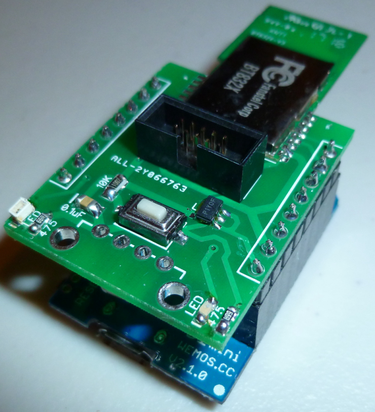
In the interest of both belt and suspenders, I gave it its own 300ma LDO so that it won't be competing with the Wemos D1 Mini for current. Earlier measurements of this Fanstel ldo-pa nRF52832 shows that it can draw up to 250ma.
It's designed to work well with ESP-LINK, which can also be used to remotely reset the nRF52832 if that's ever needed. Presently, I'm using ESP-LINK's built-in MQTT to send MQTT to a Mosquito MQTT broker. This offloads that task from the nRF52832, which just inputs/outputs serial.
By the way, I soldered the entire thing using a wide chisel point solder tip, so it turns out you don't really need a narrow solder tip after all. I do use Rosin flux, though, and it does a great job. The only inconvenience is that the excess Rosin flux should be cleaned off afterward, but, meh, I don't find that to be much of a bother.
-
@neverdie said in nRF5 Bluetooth action!:
Nice!
I'll be very interested to know how the range compares. At least so far, in my own comparisons, smaller has meant less range. Not necessarily a deal killer though, as you only need range that's "good enough," and you can compensate with a better antenna on the gateway.
Yes I'll try to test next week to have an idea of the range, if it's "good enough" to be usable at least with a central pa/lna gateway or if it's better to stick with bigger PCB antennas.
nrf51822-04 is small enough but this one has a better chip and 11 I/Os available, that's precious for a multisensor board.@nca78 said in nRF5 Bluetooth action!:
@neverdie said in nRF5 Bluetooth action!:
Nice!
I'll be very interested to know how the range compares. At least so far, in my own comparisons, smaller has meant less range. Not necessarily a deal killer though, as you only need range that's "good enough," and you can compensate with a better antenna on the gateway.
Yes I'll try to test next week to have an idea of the range, if it's "good enough" to be usable at least with a central pa/lna gateway or if it's better to stick with bigger PCB antennas.
nrf51822-04 is small enough but this one has a better chip and 11 I/Os available, that's precious for a multisensor board.Any update?
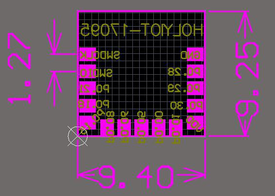
Also, what is the size of the pads? The only info I've found is what appears on the aliexpress website, which only seems to express the distance (center to center) between the pads. I just received some of these modules, so I'd like to maybe do a prototype PCB using my CNC machine. ;)
BTW, I notice that the price went up from $3.20/module to $4/module. :( And something tells me it will probably go higher still.
-
@nca78 said in nRF5 Bluetooth action!:
@neverdie said in nRF5 Bluetooth action!:
Nice!
I'll be very interested to know how the range compares. At least so far, in my own comparisons, smaller has meant less range. Not necessarily a deal killer though, as you only need range that's "good enough," and you can compensate with a better antenna on the gateway.
Yes I'll try to test next week to have an idea of the range, if it's "good enough" to be usable at least with a central pa/lna gateway or if it's better to stick with bigger PCB antennas.
nrf51822-04 is small enough but this one has a better chip and 11 I/Os available, that's precious for a multisensor board.Any update?
Also, what is the size of the pads? The only info I've found is what appears on the aliexpress website, which only seems to express the distance (center to center) between the pads. I just received some of these modules, so I'd like to maybe do a prototype PCB using my CNC machine. ;)
BTW, I notice that the price went up from $3.20/module to $4/module. :( And something tells me it will probably go higher still.
@neverdie said in nRF5 Bluetooth action!:
@nca78 said in nRF5 Bluetooth action!:
@neverdie said in nRF5 Bluetooth action!:
Nice!
I'll be very interested to know how the range compares. At least so far, in my own comparisons, smaller has meant less range. Not necessarily a deal killer though, as you only need range that's "good enough," and you can compensate with a better antenna on the gateway.
Yes I'll try to test next week to have an idea of the range, if it's "good enough" to be usable at least with a central pa/lna gateway or if it's better to stick with bigger PCB antennas.
nrf51822-04 is small enough but this one has a better chip and 11 I/Os available, that's precious for a multisensor board.Any update?
Also, what is the size of the pads? The only info I've found is what appears on the aliexpress website, which only seems to express the distance (center to center) between the pads. I just received some of these modules, so I'd like to maybe do a prototype PCB using my CNC machine. ;)
BTW, I notice that the price went up from $3.20/module to $4/module. :( And something tells me it will probably go higher still.
Sorry I was busy with other things. Now my switch seems to work I will quickly finish other atmega projects and make the switch to nrf5x.
For pad sizes, I believe from the pictures below it's 1mm width (grid size is obviously 0.5mm)
-
@neverdie said in nRF5 Bluetooth action!:
@nca78 said in nRF5 Bluetooth action!:
@neverdie said in nRF5 Bluetooth action!:
Nice!
I'll be very interested to know how the range compares. At least so far, in my own comparisons, smaller has meant less range. Not necessarily a deal killer though, as you only need range that's "good enough," and you can compensate with a better antenna on the gateway.
Yes I'll try to test next week to have an idea of the range, if it's "good enough" to be usable at least with a central pa/lna gateway or if it's better to stick with bigger PCB antennas.
nrf51822-04 is small enough but this one has a better chip and 11 I/Os available, that's precious for a multisensor board.Any update?
Also, what is the size of the pads? The only info I've found is what appears on the aliexpress website, which only seems to express the distance (center to center) between the pads. I just received some of these modules, so I'd like to maybe do a prototype PCB using my CNC machine. ;)
BTW, I notice that the price went up from $3.20/module to $4/module. :( And something tells me it will probably go higher still.
Sorry I was busy with other things. Now my switch seems to work I will quickly finish other atmega projects and make the switch to nrf5x.
For pad sizes, I believe from the pictures below it's 1mm width (grid size is obviously 0.5mm)
-
@toyman said in nRF5 Bluetooth action!:
@nca78 do you move your fantastic Nmodules to nrf5 platform?
Probably, and I will switch to MYSX connector too.
-
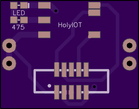
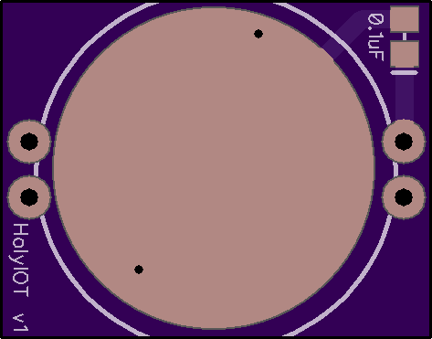
I was just about to make a test board using my CNC when out of the blue my CNC died during setup. So, I did this board instead and will have it fabbed:
-
@neverdie for a test board why are you not using standard headers and mapping all pins available ?
@nca78 Because originally I was going to do the board on my CNC (that is, before my CNC dropped dead on me), and I wanted to make it as easy as possible for the CNC to succeed. Also, for testing purposes, I'm most interested in how well it sends/receives, and I don't need many pins to test that. Also, soldering this module may be tricky, so I wanted only the minimum number of pins in case soldering it proves to be difficult.
-
Just received these tiny NRF51822 devices and would like to turn them in to MySensors 1 button scencontroller.
Where should I start?- I guess I will need some kind of USB adapter ti program them. Think I read somewhere about JLink. Would this do?
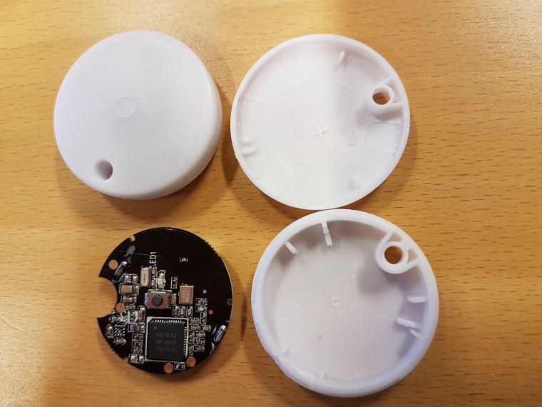
- Tomas
-
Just received these tiny NRF51822 devices and would like to turn them in to MySensors 1 button scencontroller.
Where should I start?- I guess I will need some kind of USB adapter ti program them. Think I read somewhere about JLink. Would this do?
@korttoma did you check here ?
https://forum.mysensors.org/topic/6705/mysensors-nrf5-platformFor programming the best solution is probably the NRF52 DK, it's not very expensive (30€) and you avoid all the problems related to license of the fake JLINKs (and bricking of the device if you happen to accept the invitation to update the outdated firmware on it), as it includes official licence for programming all nrf5 chips.
https://www.arrow.com/en/products/nrf52-dk/nordic-semiconductor -
Hi,
Working without problem with mysensors, I use STLink v2 from Aliexpress. LED and Button are mapped on pins 28 and 29 :)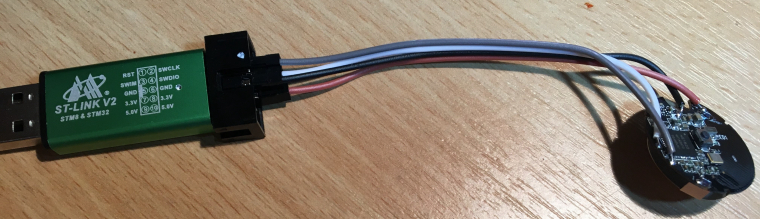
@mika :+1:
Now I feel stupid ordering the NRF52 DK for 28€. Well atleast I don't need to worry about bricking any devices.
Do you have an example sketch for the device you can share?
Is it possible to somehow monitor the battery status?- Tomas
-
@mika :+1:
Now I feel stupid ordering the NRF52 DK for 28€. Well atleast I don't need to worry about bricking any devices.
Do you have an example sketch for the device you can share?
Is it possible to somehow monitor the battery status?@korttoma said in nRF5 Bluetooth action!:
Is it possible to somehow monitor the battery status?
One of @d00616 's demo sketches allows you to read the voltage that's powering the nRF5. Assuming there is no booster involved on this device (seems unlikely), that would be the same as the battery voltage.
-
Just received these tiny NRF51822 devices and would like to turn them in to MySensors 1 button scencontroller.
Where should I start?- I guess I will need some kind of USB adapter ti program them. Think I read somewhere about JLink. Would this do?
-
- Tomas