nRF5 action!
-
Also If I want to change the UART pins to other pins would it work without errors or If I want to use 2 or more UARTS? same with I2C
Also what are the debugging options available sins the RS232 is not connected to the MCU like in an arduino how would I set stop points or peek at variables values to see if the code runs as expected?
-
@Mike_Lemo said in nRF5 Bluetooth action!:
you should follow this schematic design if you want to get this module working.
There's a bunch of similar looking schematics in the nRF52832 datasheet for the nRF52832 chip itself, but I'm not sure which of them, if any, is applicable to the Ebyte module. I guess maybe Ebyte needs a demo board schematic like Raytac has. Either that, or we need a schematic of what's on the Ebyte module itself. As it stands, I think maybe there's no enough info with which to move ahead on wiring up the Ebyte module. Am I wrong? Come to think of it, I think some of the other Chinese modules I ordered from Aliexpress may also be similar "mystery" modules. :(
-
Also If I want to change the UART pins to other pins would it work without errors or If I want to use 2 or more UARTS? same with I2C
Also what are the debugging options available sins the RS232 is not connected to the MCU like in an arduino how would I set stop points or peek at variables values to see if the code runs as expected?
@Mike_Lemo said in nRF5 Bluetooth action!:
Also If I want to change the UART pins to other pins would it work without errors or If I want to use 2 or more UARTS? same with I2C
The Chip has a lot of periphery on it. You can connect most components to pins. There is only one hardware UART, which can be connected. Please look at the Infocenter The arduino-nrf5 port is limited to things are implemented with arduino-samd by the author. This is the reason I have implemented an extension for hwPinMode() in MySensors.
Another fine thing is the implementation of Shortcuts and the PPI. You can do a lot without using the CPU.
@Mike_Lemo said in nRF5 Bluetooth action!:
Also what are the debugging options available sins the RS232 is not connected to the MCU like in an arduino how would I set stop points or peek at variables values to see if the code runs as expected?
Debugging depends on your programmer and flashing tool. I think you can start by search for "openocd gdb". OpenOCD is the flashing tool in arduino-nrf5 for all supported programmers.
-
It looks as though raytec does make two modules for the nRF52832 that has a PCB antenna rather than a chip antenna: the MDBT42Q-P and the MDBT-42V-P:
http://statics3.seeedstudio.com/assets/file/bazaar/product/MDBT42Q-Version_B.pdf
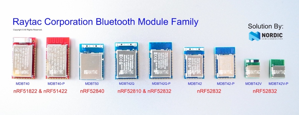
The MDBT-42V-P looks nice because of its small size. Anyone know where it can be purchased? All of a sudden, buying a module that comes with a proper datasheet seems appealing. -
It looks as though raytec does make two modules for the nRF52832 that has a PCB antenna rather than a chip antenna: the MDBT42Q-P and the MDBT-42V-P:
http://statics3.seeedstudio.com/assets/file/bazaar/product/MDBT42Q-Version_B.pdf
The MDBT-42V-P looks nice because of its small size. Anyone know where it can be purchased? All of a sudden, buying a module that comes with a proper datasheet seems appealing. -
@Mike_Lemo said in nRF5 Bluetooth action!:
@NeverDie I had mine from seeed studio
This one? https://www.seeedstudio.com/MDBT42Q-nRF52832-based-BLE-module-p-2736.html
-
I was just now noticing that Nordic has a very convenient list of third party modules (and their dimensions) that use the Nordic nRF52832 chips: https://www.nordicsemi.com/eng/Products/3rd-Party-Bluetooth-low-energy-Modules
-
FWIW, I just now sent an email to support@cdebyte.com requesting either a schematic of their E73-2G4M04S module itself or a schematic for a demo circuit, so that I may be certain about adding the appropriate hardware needed to get their module to work. I'll post if I hear anything back from them.
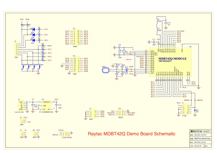
By the way, in the case of Raytac, they even have their own demo board: https://raytac.blog/2017/01/24/how-to-use-raytac-mdbt42q-nordic-nrf52832-demo-board/
-
I saw this in the MDBT42Q module datasheet, and perhaps it explains the relatively poor performance of the nRF52832 Adafruit Feather which uses the MDBT42Q.:
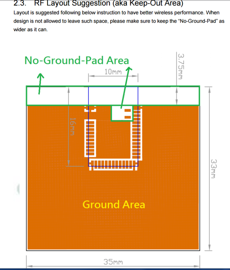
I believe the Adafruit may have a much smaller ground plane than what is being recommended here by Raytac. -
FWIW, I just now sent an email to support@cdebyte.com requesting either a schematic of their E73-2G4M04S module itself or a schematic for a demo circuit, so that I may be certain about adding the appropriate hardware needed to get their module to work. I'll post if I hear anything back from them.
By the way, in the case of Raytac, they even have their own demo board: https://raytac.blog/2017/01/24/how-to-use-raytac-mdbt42q-nordic-nrf52832-demo-board/
I requested the schematic for the cdebyte module too...but they replied: it's confidential - LOL.
-
I requested the schematic for the cdebyte module too...but they replied: it's confidential - LOL.
@mtiutiu
How long did it take them to reply to you?I guess we may have to reverse engineer what they did then--at least roughly--in order to use it. I'll see if I can pry the cover off and photograph what's inside. If I'm successful, then I'll post the photos so we can all look at it together.
-
@mtiutiu
How long did it take them to reply to you?I guess we may have to reverse engineer what they did then--at least roughly--in order to use it. I'll see if I can pry the cover off and photograph what's inside. If I'm successful, then I'll post the photos so we can all look at it together.
-
About 6 hours. I asked them too if the Nordic datasheet recommendations were followed or not and if they can provide an example of how to use the module.
@mtiutiu said in nRF5 Bluetooth action!:
if they can provide an example of how to use the module
What was their answer to that, or is it still pending? I don't mind them being a black box, provided they show how to use it.
-
I requested the schematic for the cdebyte module too...but they replied: it's confidential - LOL.
@mtiutiu said in nRF5 Bluetooth action!:
I requested the schematic for the cdebyte module too...but they replied: it's confidential - LOL.
this one is funny, like if there was something special in their module :laughing:
-
@mtiutiu said in nRF5 Bluetooth action!:
if they can provide an example of how to use the module
What was their answer to that, or is it still pending? I don't mind them being a black box, provided they show how to use it.
-
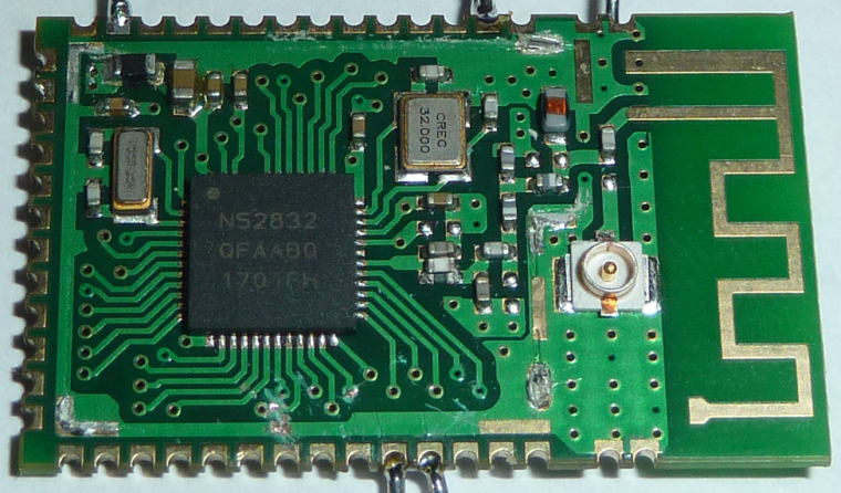
Here's a photo taken from the opposite angle:
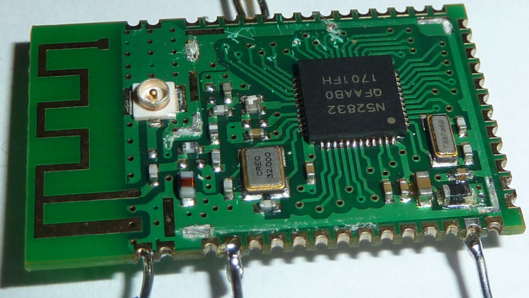
Any other photos anyone wants to see?
-
Here's the back:
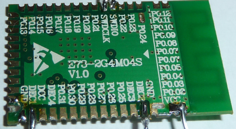
So, is it 4 layer as they claim, or only 2? Some of those vias seem rather pointless if it were only 2 layer. -
So, to Scalz's earlier point, it looks like indeed there is no capacitor already on DEC1. Regarding DEC2, it appears that there are pads and solder paste for a capacitor, but the capacitor appears to be missing! Manufacturing error?
-
@NeverDie
cool. well you just have to check continuity.
Yes this a 4layers. better for compact RF imho, else worse performance, EMI etc.. I think it's also easier to get FCC with 4layers design (not sure if this module is FCC though)My bad, i've just reread what i wrote. With nrf52 ic, I've rechecked, I'm using:
- DEC1: 100nf
- DEC2: nothing
- DEC3: 100pf
- DEC4: 1uF (and you add inductors with DCC, for DC/DC mode but it can decrease 1dB if i remember well)