nRF5 action!


  • Hardware Contributor

    @NeverDie how many GND pins did you connect ?
    It might be a stupid suggestion but maybe all GND pins are not connected together ?


  • @Mike_Lemo

    http://www.arduino.org/learning/reference/ble

    This is their "homework" in anticipation of Primo launch. It does support nrf52


  • Hardware Contributor

    Ok, so after posting some questions to CDSENET Aliexpress store(in regards to the E73-2G4M04S module):

    1. Is the nrf52832 IC DEC1 pin decoupled with a 100nF capacitor as per Nordic datasheet recommendations?
    2. Is the nrf52832 IC  DEC2 pin decoupled with a 100pF capacitor as per Nordic datasheet recommendations?
    3. Are all the power pins of the nrf52832 IC decoupled as per  Nordic datasheet recommendations?
    4. Are the external components already provided so that the internal DC-DC converter can be used?
    

    I received this part of schematic:

    0_1500878901299_E73-2G4M04S.png

    The module that I bought is this one: CDSENET E73-2G4M04S

    I hope that it helps demystify some things in regards to this module. Maybe @NeverDie can confirm this by checking his module connections as seen in the above schematic. I'm saying this because Chinese support is well..not so user friendly in my experience and I don't know if the above schematic is indeed what they used on their module or they just provided me an example schematic of how to use the NRF52832 IC in general instead.


  • Hardware Contributor

    @Mike_Lemo @Toyman
    BLEPeripheral lib from sandeep is working fine with nrf52832, as i'm using it ๐Ÿ˜‰

    Regarding the sch above, it looks like a classic circuit (in LDO mode, not surprising as DCDC mode is optional). I'm not using same values but this should work..


  • Hero Member

    They sent me two files, but I have no idea what they are, or how to open them. Maybe someone here recognizes them or can open them?
    0_1500890784640_E73-2G4M04S-PCBLIB.PCBLIB
    0_1500890793687_E73-2G4M04S-PCB-V1.0.PCBDOCPreview


  • Hero Member

    @scalz said in nRF5 Bluetooth action!:

    @Mike_Lemo @Toyman

    Regarding the sch above, it looks like a classic circuit (in LDO mode, not surprising as DCDC mode is optional). I'm not using same values but this should work..

    From what little I've read in the nRF52832 datasheet (and please do correct me if I'm wrong), the LDO mode is the "default", and is not as power efficient as the DCDC mode. Not good, as most of us probably want this for battery operation. Therefore, even if it were to work in LDO mode, what we should probably want is the DCDC mode. So, are we screwed? Or, can DCDC mode be easily applied on top of whatever they've already hardwired in the module by just adding a few more components?


  • @Toyman said in nRF5 Bluetooth action!:

    @Mike_Lemo

    http://www.arduino.org/learning/reference/ble

    This is their "homework" in anticipation of Primo launch. It does support nrf52

    @scalz said in nRF5 Bluetooth action!:

    @Mike_Lemo @Toyman
    BLEPeripheral lib from sandeep is working fine with nrf52832, as i'm using it ๐Ÿ˜‰

    Regarding the sch above, it looks like a classic circuit (in LDO mode, not surprising as DCDC mode is optional). I'm not using same values but this should work..

    If you say so that's great I've downloaded that BLEPeripheral library opened one of the test and led examples and there are a few things I don't understand why would I have to define those IRQ pins and include SPI library to use the BLE on board?

    If order to send data back and forth between peripheral and central you have to use this function:?

    to read: switchCharacteristic.value();
    to write:characteristic.setValue(value, length);

    do you maybe have a little simple example to establish a connecting between central and peripheral with sending random data and peripheral and a smartphone?


  • Hardware Contributor

    @NeverDie

    For DC-DC converter you need to add some external inductor(s) and some capacitor to the DCC pin if I remember correctly. This can be observed here:
    0_1500899991486_nrf52832_dc_dc.png

    And more than that it needs to be enabled from the SDK also.

    I didn't read the official datasheet and the recommendations from it yet...so I don't know all the implications.

    From what I've read so far this needs to be added before anything else(I think a good place is the before hook from MySensors):

    void before() {
      NRF_POWER->DCDCEN = 1;
    }
    

    And maybe this will shed some light too: https://devzone.nordicsemi.com/question/69091/a-question-about-nrf52832s-dcdc-and-ldo/


  • Hardware Contributor

    @mtiutiu there is a little confusion ๐Ÿ™‚ this is the reference sch for nrf51. It is a bit different for nrf52.

    @Mike_Lemo no you dont need to set these pins which could be removed from the init function.
    Yes these functions are used for ble comm.
    I think sharing my unfinished code is useless (arduino & phone) if you have troubles with arduino examples. I have no time for an howto actually and little bit out of mysensors scope imho .

    The arduino examples are working fine.
    There are already written howtos at sparkfun, adafruit, blogs etc
    If you need more infos, maybe you can get more help on arduino forum too..
    And for general understanding of ble and its mechanisms (providers, services, characteristics..), you can take a look at bluetooth sig.
    Finally for custom phone app, you have to code with your preferred techno or use nordics app for simple debug


  • Hardware Contributor

    @scalz

    My bad. I corrected the initial post. Hope is all well now.

    I'm going to try this one too when I have time wt51822-s4at

    This is the cheapest of all that I found so far and yes it's not a nrf52832 but a nrf51822 - for my purpose this one is very good too. It doesn't have all the pins exposed - only 7 of them but again it should fit my general usage. I'm curious about its performance though. I'll see that when I get my hands on it. This is the official datasheet(or so it seems): https://4tronix.co.uk/picobot2/WT51822-S4AT.pdf


  • Hero Member

    @NeverDie said in nRF5 Bluetooth action!:

    They sent me two files, but I have no idea what they are, or how to open them. Maybe someone here recognizes them or can open them?
    0_1500890784640_E73-2G4M04S-PCBLIB.PCBLIB
    0_1500890793687_E73-2G4M04S-PCB-V1.0.PCBDOCPreview

    Opening the first file in notepad, I notice that it says, "PCB 6.0 Binary Library File ". I had asked Ebyte for either the module schematic or a reference design using their part, so I'm guessing this is it, in some sort of PCB CAD file.


  • Hardware Contributor

    @NeverDie

    I think they use Altium Designer and that those are files generated with it.


  • @mtiutiu if so, the free viewer is available at their site


  • Hardware Contributor

    @mtiutiu I have ordered a few of those modules too, the big question is antenna performance as it seems rather small.
    It's incredibly cheap and has enough pins to drive most of the MySensors nodes, too bad it's missing the 32K crystal for low power Bluetooth ๐Ÿ˜ž


  • Hardware Contributor

    @Nca78

    I think that if we use a serial gw based on nrf24l01 pa lna variant should help cover a regular house. At least this is my intent but until then I need to prepare some test environment. And if using nrf5 repeater nodes also should help with coverage - this doesn't work for battery powered nodes I know. But I think there should be some nrf5 nodes that are powered permanently - like actuators for example.


  • Hardware Contributor

    @NeverDie

    Can you upload those files somewhere so that I can download them? I can't do that from the links you pasted here in this forum.

    I also found this altium -> kicad online converter but I don't know how well it works.


  • Hero Member

    @mtiutiu said in nRF5 Bluetooth action!:

    Can you upload those files somewhere so that I can download them? I can't do that from the links you pasted here in this forum.

    https://spaces.hightail.com/space/WMbime1pXn


  • Hardware Contributor

    @NeverDie

    Doesn't work for me so maybe it would be best to obtain a pdf or something readable for all of us from the manufacturer.


  • Hero Member

    Is no one else able to download the files either?


  • Hero Member

    @Nca78 said in nRF5 Bluetooth action!:

    @NeverDie how many GND pins did you connect ?
    It might be a stupid suggestion but maybe all GND pins are not connected together ?

    Good question. I connected to just one GND pin. However, I just now checked with a DMM, and all the exposed GND pins on the module have continuity to one another. So, based on that, I'm assuming any additional outside connections would be redundant anyway?


  • Mod

    @NeverDie said in nRF5 Bluetooth action!:

    Is no one else able to download the files either?

    From the forum, no. From hightail, yes.
    I don't know which program to open them in though.


  • Hero Member

    @mfalkvidd said in nRF5 Bluetooth action!:

    I don't know which program to open them in though

    The current theory (see above) is that maybe it's Altium Designer, which has a free viewer.


  • Hero Member

    @NeverDie said in nRF5 Bluetooth action!:

    One thing I notice on the Ebyte module is that no RESET pin is exposed. Isn't that a bit odd?

    Correction: According to the Nordic datasheet, PO.21, which is exposed on the Ebyte modle, can also serve as the reset pin. I was thrown off because Sparkfun labeled it RESET on their board's silkscreen, not "PO.21".


  • Hero Member

    @Nca78 said in nRF5 Bluetooth action!:

    I have ordered a few of those modules too,

    Do let us know if either of you are able to program it. After this Ebyte experience, I won't be taking it for granted anymore.


  • Mod

    @NeverDie not sure if it applies to this case, but at 18:04 in https://youtu.be/JXQLI-nXqmQ it is mentioned that the chip's identifier needs to be included in some list when the softdevice is compiled (or something along those lines, I am not yet familiar with the vocabulary).


  • Hero Member

    @mfalkvidd said in nRF5 Bluetooth action!:

    @NeverDie not sure if it applies to this case, but at 18:04 in https://youtu.be/JXQLI-nXqmQ it is mentioned that the chip's identifier needs to be included in some list when the softdevice is compiled (or something along those lines, I am not yet familiar with the vocabulary).

    My understanding (which may be wrong) is that in this context a "softdevice" is a veiled reference to the bluetooth stack and/or related bluetooth code, which at present the mysensors code isn't using. In any case, when I programmed both the adafruit and the sparkfun using the mysensors code, I didn't include a chip identifier in a list, nor any soft devices, and it worked anyway.


  • Hero Member

    I was thinking that maybe the Ebyte module is stuck in some kind of reset mode, but I just now checked pin P0.21 (the reset pin), and it measures high at 3.3v. This is the same as for the Sparkfun board, which I have no trouble programming. Reset is active low.


  • Contest Winner

    @NeverDie said in nRF5 Bluetooth action!:

    My understanding (which may be wrong) is that in this context a "softdevice" is a veiled reference to the bluetooth stack and/or related bluetooth code, which at present the mysensors code isn't using. In any case, when I programmed both the adafruit and the sparkfun using the mysensors code, I didn't include a chip identifier in a list, nor any soft devices, and it worked anyway.

    I haven't tested MySensors with a present SoftDevice. The drivers/NVM code (EEPROM emulation) conflicts with the DFU bootloader.

    It's better to see the SoftDevice as an Operating System providing BLE functionality and some hardware abstraction, while MySensors is directly ported to the hardware.


  • @NeverDie stupid question: did you try to power it NOT from DK board and vise versa?


  • Hero Member

    @Toyman said in nRF5 Bluetooth action!:

    @NeverDie stupid question: did you try to power it NOT from DK board and vise versa?

    Thanks for the suggestion! So far I've tried powering it from a USB 3.3v source (which is how I successfully programmed the adafruit and sparkfun boards), but I'll now try powering it from the DK and see if it makes a difference.

    By the way, I found an alternate way to confirm that the board is using the built-in LDO rather than the DCDC converter. DEC4 is the output of the LDO, and it measures 1.3v (which is also the expected voltage output by the LDO if it were active). DCC is the output of the DCDC converter, and it measures 0.0v. So, empirical confirmation of what you all inferred earlier. ๐Ÿ™‚


  • Hero Member

    @Toyman said in nRF5 Bluetooth action!:

    @NeverDie stupid question: did you try to power it NOT from DK board and vise versa?

    Just now tried it, and unfortunately it didn't make a difference. ๐Ÿ˜ž

    The actual text of the error message that I always receive is:

    c:/users/david/appdata/local/arduino15/packages/sandeepmistry/tools/gcc-arm-none-eabi/5_2-2015q4/bin/../lib/gcc/arm-none-eabi/5.2.1/../../../../arm-none-eabi/bin/ld.exe: warning: changing start of section .heap by 4 bytes
    c:/users/david/appdata/local/arduino15/packages/sandeepmistry/tools/gcc-arm-none-eabi/5_2-2015q4/bin/../lib/gcc/arm-none-eabi/5.2.1/../../../../arm-none-eabi/bin/ld.exe: warning: changing start of section .stack_dummy by 4 bytes
    Sketch uses 26932 bytes (5%) of program storage space. Maximum is 524288 bytes.
    Open On-Chip Debugger 0.10.0-dev-00254-g696fc0a (2016-04-10-10:13)
    Licensed under GNU GPL v2
    For bug reports, read
    http://openocd.org/doc/doxygen/bugs.html
    debug_level: 0
    swd
    adapter speed: 10000 kHz
    cortex_m reset_config sysresetreq
    nrf52.cpu: target state: halted
    target halted due to debug-request, current mode: Thread
    xPSR: 0x01000000 pc: 0x000008e4 msp: 0x20000400
    ** Programming Started **
    auto erase enabled
    Error: Cannot erase protected sector at 0x0
    Error: failed erasing sectors 0 to 6
    embedded:startup.tcl:454: Error: ** Programming Failed **
    in procedure 'program'
    in procedure 'program_error' called at file "embedded:startup.tcl", line 510
    at file "embedded:startup.tcl", line 454
    the selected serial port at file "embedded:startup.tcl", line 454
    does not exist or your board is not connected

    So maybe the root of the problem is that I need to do something to enable it to erase the protected sector at 0x0? That seems to be the point after which everything falls apart.


  • Mod

    @NeverDie sorry, the ID doesn't need to be in the softdevice. It needs to be in the code for the black magic probe. Might still not be related though.


  • Mod

    @NeverDie said in nRF5 Bluetooth action!:

    Error: Cannot erase protected sector at 0x0

    Could this be related to the readback protection? The video I linked before recommends issuing "monitor erase_mass" to completely reset the device and any protection.


  • Hero Member

    @mfalkvidd said in nRF5 Bluetooth action!:

    @NeverDie said in nRF5 Bluetooth action!:

    Error: Cannot erase protected sector at 0x0

    Could this be related to the readback protection? The video I linked before recommends issuing "monitor erase_mass" to completely reset the device and any protection.

    Good one! I have a hunch you may have just cracked the problem.

    I see no harm in trying a mass erase before the programming step, so I'll give it a go.


  • Hardware Contributor

    @mfalkvidd said in nRF5 Bluetooth action!:

    @NeverDie said in nRF5 Bluetooth action!:

    Is no one else able to download the files either?

    From the forum, no. From hightail, yes.

    Direct click fails. But if you press Control key while you click, to open in a new tab, then you should be able to download files from the forum ๐Ÿ˜‰


  • Contest Winner

    @mfalkvidd said in nRF5 Bluetooth action!:

    Could this be related to the readback protection? The video I linked before recommends issuing "monitor erase_mass" to completely reset the device and any protection.

    This is a simple sketch for mass erasing a nRF5 MCU. Just compile it with the option a SoftDevice is present, when a SoftDevice is present:

    #include "nrf.h"
    
    void wait_for_ready()
    {
            while (NRF_NVMC->READY == NVMC_READY_READY_Busy) {
            };
    }
    
    
    void setup() {
            // Enable erasing flash
            NRF_NVMC->CONFIG = NVMC_CONFIG_WEN_Een << NVMC_CONFIG_WEN_Pos;
            wait_for_ready();
    
            // Erase Flash and UICR
            NRF_NVMC->ERASEALL = 1;
            wait_for_ready();
    
            // Disable erasing
            NRF_NVMC->CONFIG = NVMC_CONFIG_WEN_Ren << NVMC_CONFIG_WEN_Pos;
            wait_for_ready();
    
    }
    
    void loop() {
    }```

  • Hero Member

    You would think that the programmer device would just do a mass erase as part of its standard procedure, though, so it's a bit odd that it would require me to do it manually. The mass erase that Roger Clark did with his Black Magic Probe seemed nearly instant. I don't have a Black Magic Probe though.

    In any case, I can't use the above sketch to do ia mass erase because it presumes I can already load a sketch onto the target--i.e. it presumes the fundamental problem is solved already.

    What's the preferred way to do a mass erase? I seem to remember seeing a mass erase as an option in one of the Nordic utility softwares, but I don't recall now which one. Anyone happen to know?


  • Hero Member

    Looking further into it, what I may need to first do is UNLOCK the Ebyte module, which appears to be a separate step from mass erasing: https://mcuoneclipse.com/2014/10/05/unlocking-and-erasing-flash-with-segger-j-link/


  • @NeverDie may be some hints here:
    https://learn.adafruit.com/bluefruit-nrf52-feather-learning-guide/flashing-the-bootloader

    And also pay attention to their Adalink tool. The support for nrf52 was added recently.


  • Hero Member

    By switching to a Windows 10 computer, I was able to get J-link working over USB from windows. Then I opened up J-Link Command, which mostly utiizes a command line interface. It turns out that for unlocking, the nRF52836 is not on the list of devices (see below), so I simply then issued a mass erase command, which looks as though it may have worked:

    J-Link>unlock
    Syntax: unlock <DeviceName>
    ---Supported devices---
      LM3Sxxx [<Auto>]
      Kinetis
      EFM32Gxxx
      LPC5460x
    J-Link>erase
    Erasing device (nRF52832_xxAA)...
    J-Link: Flash download: Total time needed: 0.336s (Prepare: 0.064s, Compare: 0.000s, Erase: 0.263s, Program: 0.000s, Verify: 0.000s, Restore: 0.008s)
    Erasing done.
    J-Link>mem 0 100
    00000000 = FF FF FF FF FF FF FF FF FF FF FF FF FF FF FF FF
    00000010 = FF FF FF FF FF FF FF FF FF FF FF FF FF FF FF FF
    00000020 = FF FF FF FF FF FF FF FF FF FF FF FF FF FF FF FF
    00000030 = FF FF FF FF FF FF FF FF FF FF FF FF FF FF FF FF
    00000040 = FF FF FF FF FF FF FF FF FF FF FF FF FF FF FF FF
    00000050 = FF FF FF FF FF FF FF FF FF FF FF FF FF FF FF FF
    00000060 = FF FF FF FF FF FF FF FF FF FF FF FF FF FF FF FF
    00000070 = FF FF FF FF FF FF FF FF FF FF FF FF FF FF FF FF
    00000080 = FF FF FF FF FF FF FF FF FF FF FF FF FF FF FF FF
    00000090 = FF FF FF FF FF FF FF FF FF FF FF FF FF FF FF FF
    000000A0 = FF FF FF FF FF FF FF FF FF FF FF FF FF FF FF FF
    000000B0 = FF FF FF FF FF FF FF FF FF FF FF FF FF FF FF FF
    000000C0 = FF FF FF FF FF FF FF FF FF FF FF FF FF FF FF FF
    000000D0 = FF FF FF FF FF FF FF FF FF FF FF FF FF FF FF FF
    000000E0 = FF FF FF FF FF FF FF FF FF FF FF FF FF FF FF FF
    000000F0 = FF FF FF FF FF FF FF FF FF FF FF FF FF FF FF FF
    J-Link>
    

    ๐Ÿ™‚


  • Hero Member

    I received the following message from the Ebyte seller:

    Sorry that the two files are incorrect, please just ignore or delete them.
    We will send correct files later.
    
    Thank you!
    

  • Hero Member

    It worked! After doing the above mass erase, the nRF52832 Ebyte Module successfully programmed from the NRF52 DK. I uploaded the mysensors lightsensor sketch, and the serialGateway running on the NRF52 DK is receiving its messages. ๐Ÿ™‚

    Many thanks to mfalkvidd for his mass erase suggestion and for his link to the Roger Clark youtube video, which had further mass erase commentary.

    Also, many thanks to d00616 for his excellent guide:
    https://www.openhardware.io/view/376/MySensors-NRF5-Platform
    Without that, I would have been lost on how to set anything up.

    Thanks to everyone else too who made comments and suggestions. This has been a great group effort with a successful outcome. ๐Ÿ™‚ ๐Ÿ™‚ ๐Ÿ™‚


  • @NeverDie wow!!! Will you write a short tutorial? Is mas erase needed for EVERY time the sketch is uploaded?


  • Hardware Contributor

    That's great news @NeverDie, thank you for your efforts and thank you also to everyone who helped !
    My modules will arrive tomorrow or on Wednesday and you have saved me hours of suffering ๐Ÿ˜„


  • Hero Member

    Just now did a very quick range test, and the Ebyte nRF52832 module seems roughly comparable to the nRF52 DK for range. i.e. much better than the Adafruit nRF52832 Feather and also much better than the non-amplified nRF24L01+'s. So, whew! What a relief that is. At least for me, that means I won't need to wait for the nRF52840.

    So, now the next question is whether the Ebyte nRF52832 can be made to run in DCDC mode, instead of LDO mode, to make it more suited for battery operation. At the moment, I'm not even sure how big or small a power savings that would equate to. Anyone know?


  • Contest Winner

    @NeverDie said in nRF5 Bluetooth action!:

    So, now the next question is whether the Ebyte nRF52832 can be made to run in DCDC mode, instead of LDO mode, to make it more suited for battery operation. However, at the moment, I'm not even sure how big or small a power savings that would equate to. Anyone know?

    There is no DCDC support for ESB radio at the moment. The DCDC mode is only efficient on high current states, like enabled radio and should only enabled in an defined voltage range.


  • Hero Member

    @Toyman said in nRF5 Bluetooth action!:

    Is mas erase needed for EVERY time the sketch is uploaded?

    Roger Clark says not. I can't say for sure yet, as I haven't yet tried. I think the answer will probably turn out to be that if you aren't doing anything to specifically protect certain flash memory locations after programming it, then you would only need to do it once to undo and erase whatever came on the chip from the factory.


  • Hardware Contributor

    @NeverDie
    like said above DCDC needs to be enabled. Then, the mcu will automatically switch between LDO mode (for light loads) and DCDC mode for higher currents loads like when mcu is wake up, or during radio comms etc.. Can be interesting in some cases.
    in datasheet, DCDC mode can divide by two mcu power consumption. Side effects could be -1dB sensitivity, so it's better to filter well by using two inductors (see ref design)


  • Contest Winner

    I have found a simple way to mass erase the MCU. Select "None" as SoftDevice and use the "Burn Bootloader" function. There is an error generated but the device is erased.


  • Hero Member

    @mtiutiu said in nRF5 Bluetooth action!:

    I'm going to try this one too when I have time wt51822-s4at

    I used your link to order some of those modules just now. They're so small and cheap that they might be nice for simple things.

    With the Ebyte module now working, I'm feeling emboldened again. ๐Ÿ™‚


  • Hero Member

    Which nRF52832 pins do I use for the mysensors implementation of UART Tx and Rx on the nRF52832? When I looked in Nordic's nRF52832 datasheet (http://infocenter.nordicsemi.com/pdf/nRF52832_PS_v1.3.pdf), I didn't see any pins specifically assigned/reserved for that purpose.


  • Hardware Contributor

    by default nrf52dk is RX(24) and TX(25).
    for adafruit, i have not installed the board..but you can check in adafruit howto (or in their variant files).

    Peripherals are not fixed, that's a big advantage vs simple 8bits mcu. You define them when doing your design (sometimes it may need some checks in datasheet, depends on mcu).

    So, for your ebyte module your options are:

    • create a new board for the board manager (see variant files) regarding a specific design.
    • or you don't care of this for the moment, and you can simply use nrf52dk board and use the same mapping.
    • or, in the same order, use adafruit board and their mapping (or sparkfun board etc.., no matter, just check their board map pictures )

  • Contest Winner

    @scalz said in nRF5 Bluetooth action!:

    So, for your ebyte module your options are:

    I working on the fourth option, I publish soon:

    • Define the pin mapping in your sketch, then its part of your code

    Like @scalz has written. Place the MCU in your layout and define the pin mapping later. Exceptions are analog pins, comparator pins , NFC pins, reset... The pins are documented in Infocenter: Pin assignments Please look at the "GPIO usage restrictions" chapter too.


  • Hardware Contributor

    @NeverDie

    For the ebyte nrf52832 based modules did you had to wire some external components? Are there some other requirements for it in order to work?

    Thanks.


  • Hero Member

    @mtiutiu said in nRF5 Bluetooth action!:

    @NeverDie

    For the ebyte nrf52832 based modules did you had to wire some external components? Are there some other requirements for it in order to work?

    Thanks.

    For proof of concept purposes, I had just 4 wires connected for programming: PWR, GND, SWDIO, and SWDCLK. After programming for range testing: just PWR and GND. I'll soon be adding UART Tx so that I can also read its serial console output.


  • Hero Member

    @scalz
    Thanks for the explanation. I had been programming it as a "Generic nRF82832," and I don't know what that mapping is. However, I can just as easily pick one of the alternatives you listed, such as the D.K, to get a predictable pin mapping.

    @d00616
    Your idea of having the pin mapping be selectable within the sketch sounds great! A+. I'm really looking forward to that and hope that you can do it soon. It sounds much easier for noobs like me than having to futz about with finding/changing/installing other files, and maybe also making it easier to share with and/or borrow from other makers.


  • Hardware Contributor

    Not related to Bluetooth but @NeverDie did you also receive small antennas and ipx->sma adapters with your modules ?
    I received one for each nrf52 and also one for the pa lna nrf24. I was not expecting them as those modules all have a PCB antenna and ipx is just an option.


  • Hero Member

    @Nca78 said in nRF5 Bluetooth action!:

    did you also receive small antennas and ipx->sma adapters with your modules ?

    Nope.


  • Hero Member

    @scalz said in nRF5 Bluetooth action!:

    nrf52dk is RX(24) and TX(25)

    Hmm.. Where is that defined exactly? I just now tried hooking the Tx(25) of an actual nrf52DK to the Rx pin of a FTDI connector, and GND to GND, but I'm not seeing any output from the nrf52DK, even though I should be. I'm assuming that by 25 you're referring to PO.25 and not pin 25 on the chip?


  • Hero Member

    I googled up this diagram:
    alt text
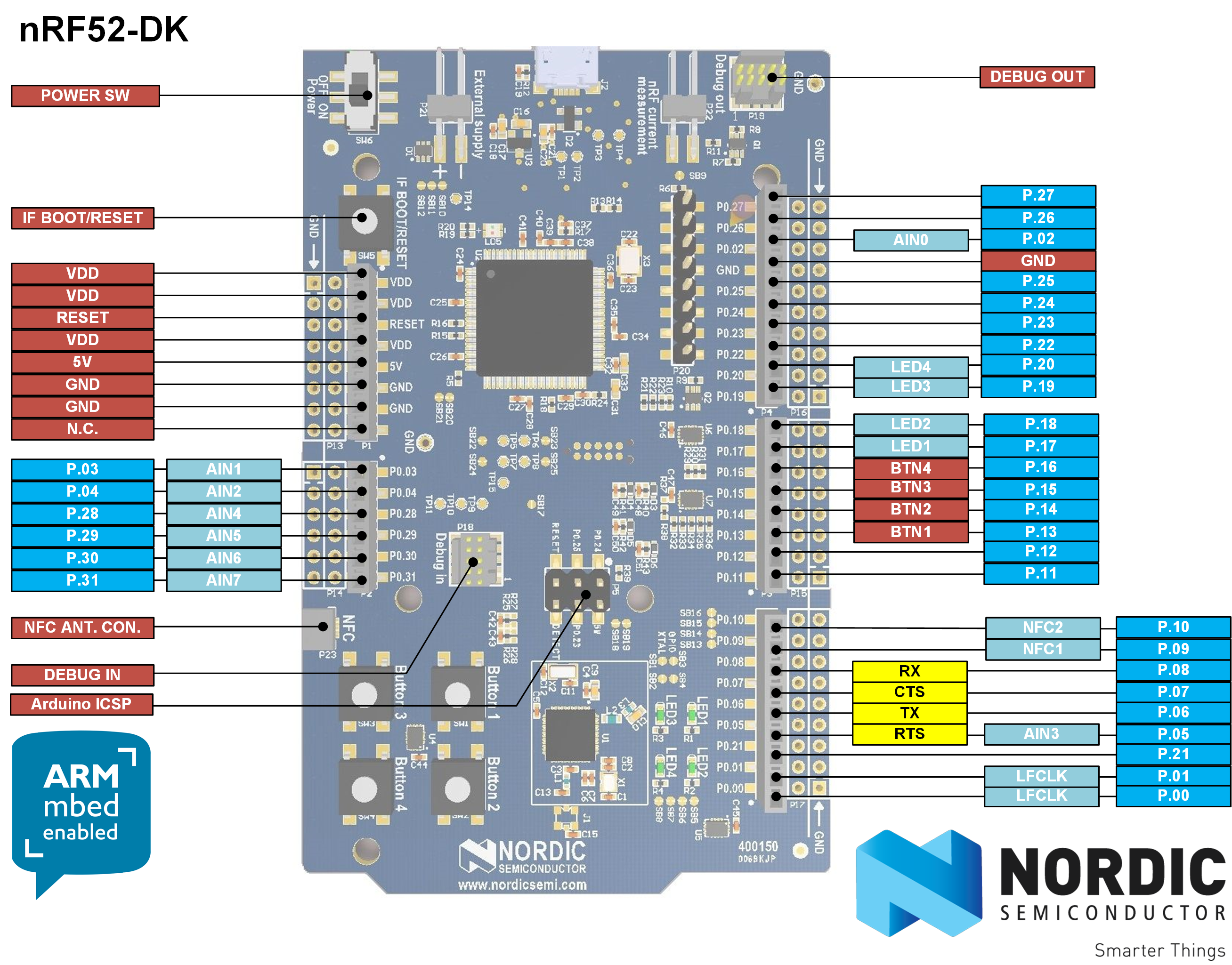
    Looks as though TX is maybe P0.06. I'll try that....


  • Hero Member

    Confirmed: Pin P0.06 works as Uarte TX on the nRF52 DK. ๐Ÿ™‚


  • Hardware Contributor

    @NeverDie yes, you're right ๐Ÿ‘ sorry i misread it ๐Ÿ˜Š
    Have fun!


  • Hero Member

    As final confirmation I did re-program the Ebyte module as an nRF52 DK, then connected its P0.06 to the FTDI RX, and, voilร  , it worked as expected. @scalz Thanks for the idea! ๐Ÿ™‚

    One small caveat: On the Ebyte module, P0.06 doesn't appear on the silkscreen (there's a typo where it's shown as P0.07 instead, resulting in there being two P0.07's on the silkscreen), so just pick the most obvious pin based on the numerical progression (or else consult the datasheet), and it will work.


  • Hero Member

    In lieu of my breakout board, which hasn't yet arrived, I've been attaching wires directly to the module so that I can do more than just sit and wait for the BoB delivery. I'm now doing it this way:
    0_1501085660176_attachments.jpg
    and although crude it's working much better than just soldering the wire to the module with no mechanical support. Doing it the way pictured, the connections stay connected and don't break loose. ๐Ÿ™‚ Ironically, by the time my breakout boards finally do arrive, I may have already learned everything I needed them for.

    I am curious: how are the rest of you handling this issue?

    [Edit: One other alternative: once my 1.27mm pitch generic protoboards arrive, I expect they'll offer up cleaner connection possibilities. At the moment, I'm also waiting for them to arrive from Aliexpress....]


  • Contest Winner

    @NeverDie said in nRF5 Bluetooth action!:

    Your idea of having the pin mapping be selectable within the sketch sounds great! A+. I'm really looking forward to that and hope that you can do it soon.

    With merging this pull request the feature should be available: https://github.com/mysensors/ArduinoBoards/pull/13

    Documentation can be found at https://github.com/mysensors/ArduinoHwNRF5


  • Contest Winner

    @d00616 said in nRF5 Bluetooth action!:

    With merging this pull request the feature should be available: https://github.com/mysensors/ArduinoBoards/pull/13

    Merged. Have fun with board definition in your sketch.


  • Hardware Contributor

    @NeverDie said in nRF5 Bluetooth action!:

    I am curious: how are the rest of you handling this issue?

    Not many solutions, I soldered wires directly to the modules too, I used thin&cheap wires from aliexpress. They are very convenient for this, easy to solder and very soft so not having any constraint on the solder joints when you manipulate them. Then I put module on the side of board with double sided tape and soldered other ends of the wires to a connector.
    0_1501138745943_nrf52_1.jpg
    Then I flip everything and only look at the beautiful side of things ๐Ÿ˜„
    0_1501138753206_nrf52_2.jpg


  • Hero Member

    @d00616 said in nRF5 Bluetooth action!:

    @d00616 said in nRF5 Bluetooth action!:

    With merging this pull request the feature should be available: https://github.com/mysensors/ArduinoBoards/pull/13

    Merged. Have fun with board definition in your sketch.

    Thanks! By being "merged," does that mean it is now in the regular MySensors development release, and so I should reload a fresh copy of the MySensors development library?

    Also, is this the way I should enable P0.21 as nReset (to enable hardware resets on P0.21), or should I instead be writing 0xFFFF directly to both the PSELRESET[0] and PSELRESET[1] registers to enable that?


  • Mod

    This post is deleted!

  • Contest Winner

    @NeverDie said in nRF5 Bluetooth action!:

    Thanks! By being "merged," does that mean it is now in the regular MySensors development release, and so I should reload a fresh copy of the MySensors development library?

    The Board definition is independed from MySensors core living at https://github.com/mysensors/ArduinoBoards You have to follow the instructions, then you can install the MySensors nRF5 Boards via Arduino Board Manager.

    Also, is this the way I should enable P0.21 as nReset (to enable hardware resets on P0.21), or should I instead be writing 0xFFFF directly to both the PSELRESET[0] and PSELRESET[1] registers to enable that?

    Look into the Tools menu. For nRF52 MCU is a "Reset" menu. Switch it to "Enable"


  • Hero Member

    @d00616
    I got the pin mapping to work, but setting reset enable through the tool menu seems to have no effect. I subsequently drive P0.21 low (all the way to GND even), but no reset happens. Am I doing it wrong? Anyone gotten it to work?


  • Hero Member

    @NeverDie
    I also tried adding a 10K pullup resistor, and no change.

    At the moment I'm unfamiliar with the nRF52 API. What would the code be to set both those reset registers to 0xFFFF? That by itself should enable the reset on P0.21. I could try inserting it into the demo script and see if reset then works.


  • Hero Member

    I guess it wouldn't be that simple, because I just now read that it requires a system reset after writing to those registers: https://devzone.nordicsemi.com/question/157603/can-i-enable-and-disable-nrf52832-reset-pin-when-code-is-running/ for it to take effect.


  • Hardware Contributor

    @NeverDie said in nRF5 Bluetooth action!:

    By switching to a Windows 10 computer, I was able to get J-link working over USB from windows.

    Can you explain the steps you used for that ?
    Did you use a jlink clone or the version included in the DK ?


  • Hardware Contributor

    @Nca78 said in nRF5 Bluetooth action!:

    @NeverDie said in nRF5 Bluetooth action!:

    By switching to a Windows 10 computer, I was able to get J-link working over USB from windows.

    Can you explain the steps you used for that ?
    Did you use a jlink clone or the version included in the DK ?

    Well you can forget about my questions.
    I tried to use the JLink tools to make the mass erase but it didn't want to connect to the module.
    But then I have replaced the driver with Zadig and configured Arduino for NRF5 and it uploaded the LightSensor sketch, I can see it in the log of the controller. No mass erase needed, nor any unlock or related command.
    Just plug and program for me ๐Ÿ˜„

    I have some strange error messages but I guess they come from (very) dated firmware on my Segger clone

    ** Programming Started **
    auto erase enabled
    Info : nRF51822-QFN48(build code: B00) 512kB Flash
    Warn : not enough working area available(requested 32)
    Warn : no working area available, falling back to slow memory writes
    wrote 28672 bytes from file C:\Users\Nicolas\AppData\Local\Temp\arduino_build_723618/LightSensor.ino.hex in 6.715397s (4.170 KiB/s)
    ** Programming Finished **
    ** Verify Started **
    Warn : not enough working area available(requested 52)
    verified 27432 bytes in 0.279278s (95.923 KiB/s)
    ** Verified OK **
    ** Resetting Target **
    shutdown command invoked
    

  • Hero Member

    @Nca78 said in nRF5 Bluetooth action!:

    Did you use a jlink clone or the version included in the DK ?

    I used the j-link Segger clone to do the mass erase, and then I switched to the DK to do the programming. However, today I was able to do the programming from the Segger clone on the Windows 10 computer, and the setup is less arduous than for programming an external chip using the DK (because with the Segger I didn't have to power the target chip independently during the programming).


  • Hero Member

    So, I guess the way the code would read is:

    1. First check if the reset registers are already properly set.
    2. If so, then just move on to whatever is next.
      If not, then properly set the reset registers and invoke the system reset.

    Apparently a system reset doesn't change the values in the reset registers.

    Of course, none of this would be needed if the reset enable from the tools menu worked, so I'd still prefer to do it that way if at all possible.

    As I indicated earlier, the pin mapping on Rx and Tx did work using @d00616 new technique, so hurray for that. That much was an important victory in itself that's worth celebrating. ๐Ÿ™‚


  • Hardware Contributor

    First nrf51822 module arrived already.
    It's really small, here between an nrf24 SMD and the cdebyte 52832.
    Soldering quality looks better than the pictures on AliExpress.
    0_1501235779537_IMAG1846.jpg


  • Contest Winner

    @NeverDie said in nRF5 Bluetooth action!:

    Apparently a system reset doesn't change the values in the reset registers.

    The "Reset" menu was from my first approach creating user manageable boards for arduino-nrf5. I haven' tested it. With the reset menu I set the "-DCONFIG_GPIO_AS_PINRESET" option. This option should be processed in "cores/nRF5/SDK/components/toolchain/system_nrf52.c". If not the SystemInit() function is not processed in the startup code. This is a problem handling the chip errata. I have not time to check this at the moment.

    Here is a PR which want to enable reset as default: https://github.com/sandeepmistry/arduino-nRF5/pull/91


  • Hero Member

    Maybe the reset pin problem is hardware related? I say that because if I program the Ebyte module as a Nordic nRF52832 DK board, it still has the same issue. In contrast, the reset button on the actual nRF52832 DK board does work as expected.


  • Hero Member

    I've confirmed that connecting P0.21 to GND and then removing it again on the Nordic nRF52832 DK does act as a reset. So, at the moment I have no idea why doing so on the Ebyte nRF52832 that's been programmed to think it's an Nordic nRF52832 DK doesn't do the same. There must be some hardware difference, right?


  • Hero Member

    I've confirmed that on both the Ebyte Module and on the Nordic nRF52832 DK, there is continuity between the P0.21 pin on the chip and the P0.21 pin on the board pinout. So, there must be some other factor that accounts for the difference.


  • Hero Member

    Making no headway on the reset topic, so for now I'm going to punt and move on to other things.


  • Hero Member

    Success! I received some of these modules:
    https://www.aliexpress.com/item/nRF52832-Bluetooth-4-1-BLE-Module-M4-Transparent-Transmission-SMA-512K-FLASH-64K-RAM-pass-through/32798522093.html?spm=2114.search0104.3.10.osbQHP&ws_ab_test=searchweb0_0,searchweb201602_5_10152_10065_10151_10068_10130_10084_10083_10119_10080_10307_10082_10081_10110_10178_10137_10111_10060_10112_10113_10155_10114_10154_10056_10055_10054_10310_10312_10059_100031_10099_10078_10079_10103_10073_10102_10120_10052_10053_10142_10107_10050_10051-10120,searchweb201603_2,ppcSwitch_5&btsid=b9a0c3cb-cc2a-4254-b24f-94136c73def6&algo_expid=2a71f70b-4929-43a5-887a-2f7263250568-1&algo_pvid=2a71f70b-4929-43a5-887a-2f7263250568
    which I immediately programmed using the nRF52832 DK. This time, there was no need to first mass erase. Furthermore, this time P0.21 does indeed reset the module after it is pulled to ground and then released.

    So, from this I conclude there must be something peculiar to the Ebyte modules which prevents their resetting using P0.21.

    It's nice to have different modules to compare amongst. ๐Ÿ™‚


  • Mod

    @NeverDie gotta catch them all ๐Ÿ™‚


  • Hero Member


  • Hero Member

    Anyone have a good sketch for measuring the battery supplied voltage on an nRF52? Some of the concepts from the old atmega328p may apply, but the specifics are going to be different, I'm sure.


  • Check on adafruits feather reference they use two resistors as a voltage divider for that simple and effective.


  • Hero Member

    @Mike_Lemo said in nRF5 Bluetooth action!:

    Check on adafruits feather reference they use two resistors as a voltage divider for that simple and effective.

    I'm not finding it. Do you have a link?


  • @NeverDie https://learn.adafruit.com/assets/39913

    Top right corner of the schematic.


  • @NeverDie but a much better but more expensive solution would be a lipo fuel guage from spark fun they use a Max chip for that.


  • Hardware Contributor

    If supplied with less than 3.6V you can do it with ADC, 1.2V voltage reference and 1/3 prescaling.
    But I've only looked at the theory yet.

    Rules are Vdd+0.3V max at the pin, and max 2.4V as input of ADC (after prescaling)


  • Hero Member

    Well, as you all know, on the atmega328p you can read the 1.1v gap voltage using the battery voltage as the reference voltage, by doing analogRead(A0), and from just that one measurement then calculate the battery voltage by doing a little bit of math. So, I'm just wondering what the code is to do the equivalent of that (using 1.2v instead of 1.1v) on the nRF52832.


  • Contest Winner

    @Nca78 said in nRF5 Bluetooth action!:

    If supplied with less than 3.6V you can do it with ADC, 1.2V voltage reference and 1/3 prescaling.
    But I've only looked at the theory yet.

    For this, you can use the implemented hwCPUVoltage() function. Reading the voltage costs nRF51: 260ยตA/20ยตs | nRF52: 700ยตA/3ยตs


  • Hero Member

    @d00616 said in nRF5 Bluetooth action!:

    hwCPUVoltage()

    I'm finally installing Visual Micro, because I hope it will help me quickly find where all these functions are defined. With all these new layers, the Arduino IDE is just no longer cutting it.


  • Hero Member

    LOL. Well, Visual Micro found it alright, but just in the wrong place. It found it in MyHwAVR.cpp


  • Hardware Contributor

    @NeverDie said in nRF5 Bluetooth action!:

    @d00616 said in nRF5 Bluetooth action!:

    hwCPUVoltage()

    I'm finally installing Visual Micro, because I hope it will help me quickly find where all these functions are defined. With all these new layers, the Arduino IDE is just no longer cutting it.

    good choice ๐Ÿ‘
    for nrf5, the function is located in MyHwNRF5.cpp


  • Hero Member

    @d00616 said in nRF5 Bluetooth action!:

    For this, you can use the implemented hwCPUVoltage() function.

    I tried this function call on an nRF52 DK, and it seems to work. I then tried it on an Ebyte module, treated as an nRF52 DK "board", and it reported zero voltage. So, probably I just need to do a pin mapping so that it reads the voltage on the proper pin. But which pin/mapping would it be? I thought that Vcc wouldn't really be mappable to anything but Vcc. I guess whichever analog pin (if that's what it is?) is connected to Vcc on the nRF52 DK is the pin I need to find and re-map to its equivalent pin on the Ebyte module. Hmmm.... I'll have to look into which one that would be.


  • Hero Member

    Actually, something different may be going on. Here's the function definition:

    uint16_t hwCPUVoltage()
    {
    	// VDD is prescaled 1/3 and compared with the internal 1.2V reference
    	Serial.println("Inside hwCPUVoltage function.");
    #if defined(NRF_ADC)
        Serial.println("This is an NRF_ADC.");
    	// NRF51:
    	// Sampling is done with lowest resolution to minimize the time
    	// 20uS@260uA
    
    	// Concurrent ressource: disable
    	uint32_t lpcomp_enabled = NRF_LPCOMP->ENABLE;
    	NRF_LPCOMP->ENABLE = 0;
    
    	// Enable and configure ADC
    	NRF_ADC->ENABLE = 1;
    	NRF_ADC->CONFIG = (ADC_CONFIG_EXTREFSEL_None << ADC_CONFIG_EXTREFSEL_Pos) |
    	                  (ADC_CONFIG_PSEL_Disabled << ADC_CONFIG_PSEL_Pos) |
    	                  (ADC_CONFIG_REFSEL_VBG << ADC_CONFIG_REFSEL_Pos) |
    	                  (ADC_CONFIG_INPSEL_SupplyOneThirdPrescaling << ADC_CONFIG_INPSEL_Pos) |
    	                  (ADC_CONFIG_RES_8bit << ADC_CONFIG_RES_Pos);
    	NRF_ADC->EVENTS_END = 0;
    	NRF_ADC->TASKS_START = 1;
    	while(!NRF_ADC->EVENTS_END);
    	NRF_ADC->EVENTS_END = 0;
    	int32_t sample = (int32_t)NRF_ADC->RESULT;
    	NRF_ADC->TASKS_STOP = 1;
    	NRF_ADC->ENABLE = 0;
    
    	// Restore LPCOMP state
    	NRF_LPCOMP->ENABLE = lpcomp_enabled;
    
    	return (sample*3600)/255;
    
    #elif defined(NRF_SAADC)
    	// NRF52:
    	// Sampling time 3uS@700uA
    	Serial.println("This is an NRF_SAADC.");
    	int32_t sample;
    	NRF_SAADC->ENABLE = SAADC_ENABLE_ENABLE_Enabled << SAADC_ENABLE_ENABLE_Pos;
    	NRF_SAADC->RESOLUTION = SAADC_RESOLUTION_VAL_8bit << SAADC_RESOLUTION_VAL_Pos;
    	NRF_SAADC->CH[0].PSELP = SAADC_CH_PSELP_PSELP_VDD << SAADC_CH_PSELP_PSELP_Pos;
    	NRF_SAADC->CH[0].CONFIG = (SAADC_CH_CONFIG_BURST_Disabled << SAADC_CH_CONFIG_BURST_Pos) |
    	                          (SAADC_CH_CONFIG_MODE_SE << SAADC_CH_CONFIG_MODE_Pos) |
    	                          (SAADC_CH_CONFIG_TACQ_3us << SAADC_CH_CONFIG_TACQ_Pos) |
    	                          (SAADC_CH_CONFIG_REFSEL_Internal << SAADC_CH_CONFIG_REFSEL_Pos) |
    	                          (SAADC_CH_CONFIG_GAIN_Gain1_6 << SAADC_CH_CONFIG_GAIN_Pos) |
    	                          (SAADC_CH_CONFIG_RESN_Bypass << SAADC_CH_CONFIG_RESN_Pos) |
    	                          (SAADC_CH_CONFIG_RESP_Bypass << SAADC_CH_CONFIG_RESP_Pos);
    	NRF_SAADC->OVERSAMPLE = SAADC_OVERSAMPLE_OVERSAMPLE_Bypass << SAADC_OVERSAMPLE_OVERSAMPLE_Pos;
    	NRF_SAADC->SAMPLERATE = SAADC_SAMPLERATE_MODE_Task << SAADC_SAMPLERATE_MODE_Pos;
    	NRF_SAADC->RESULT.MAXCNT = 1;
    	NRF_SAADC->RESULT.PTR = (uint32_t)&sample;
    
    	NRF_SAADC->EVENTS_STARTED = 0;
    	NRF_SAADC->TASKS_START = 1;
    	while (!NRF_SAADC->EVENTS_STARTED);
    	NRF_SAADC->EVENTS_STARTED = 0;
    
    	NRF_SAADC->EVENTS_END = 0;
    	NRF_SAADC->TASKS_SAMPLE = 1;
    	while (!NRF_SAADC->EVENTS_END);
    	NRF_SAADC->EVENTS_END = 0;
    
    	NRF_SAADC->EVENTS_STOPPED = 0;
    	NRF_SAADC->TASKS_STOP = 1;
    	while (!NRF_SAADC->EVENTS_STOPPED);
    	NRF_SAADC->EVENTS_STOPPED = 1;
    
    	NRF_SAADC->ENABLE = (SAADC_ENABLE_ENABLE_Disabled << SAADC_ENABLE_ENABLE_Pos);
    
    	return (sample*3600)/255;
    #else
    	Serial.println("Unknown MCU!!");
    	// unknown MCU
    	return 0;
    #endif
    }
    

    One, perhaps likely, theory would be that it doesn't recognize the MCU, which would explain why it returns the value of zero. Well, to debug that, I added the Serial.println(...) statements into the library code (see above) in an attempt to see which of the if-else branches is being taken, but none of the Serial.println(...)'s were printed! Here's a sample of the output from the Ebyte Module:

    332641 TSF:MSG:SEND,255-255-255-255,s=255,c=3,t=7,pt=0,l=0,sg=0,ft=0,st=OK:
    332968 TSF:MSG:READ,0-0-255,s=255,c=3,t=8,pt=1,l=1,sg=0:0
    332973 TSF:MSG:FPAR OK,ID=0,D=1
    334649 TSM:FPAR:OK
    334650 TSM:ID
    334651 TSM:ID:REQ
    334654 TSF:MSG:SEND,255-255-0-0,s=59,c=3,t=3,pt=0,l=0,sg=0,ft=0,st=OK:
    336662 TSM:ID
    336663 TSM:ID:REQ
    336665 TSF:MSG:SEND,255-255-0-0,s=23,c=3,t=3,pt=0,l=0,sg=0,ft=0,st=OK:
    338673 TSM:ID
    338674 TSM:ID:REQ
    338676 TSF:MSG:SEND,255-255-0-0,s=242,c=3,t=3,pt=0,l=0,sg=0,ft=0,st=OK:
    340684 TSM:ID
    340685 TSM:ID:REQ
    340687 TSF:MSG:SEND,255-255-0-0,s=205,c=3,t=3,pt=0,l=0,sg=0,ft=0,st=OK:
    342695 !TSM:ID:FAIL
    342696 TSM:FAIL:CNT=7
    342698 TSM:FAIL:DIS
    342700 TSF:TDI:TSL
    402703 TSM:FAIL:RE-INIT
    402705 TSM:INIT
    402706 TSM:INIT:TSP OK
    402708 TSM:FPAR
    402711 TSF:MSG:SEND,255-255-255-255,s=255,c=3,t=7,pt=0,l=0,sg=0,ft=0,st=OK:
    403472 TSF:MSG:READ,0-0-255,s=255,c=3,t=8,pt=1,l=1,sg=0:0
    403478 TSF:MSG:FPAR OK,ID=0,D=1
    404719 TSM:FPAR:OK
    404720 TSM:ID
    404721 TSM:ID:REQ
    404724 TSF:MSG:SEND,255-255-0-0,s=241,c=3,t=3,pt=0,l=0,sg=0,ft=0,st=OK:
    406732 TSM:ID
    406733 TSM:ID:REQ
    406735 TSF:MSG:SEND,255-255-0-0,s=205,c=3,t=3,pt=0,l=0,sg=0,ft=0,st=OK:
    408743 TSM:ID
    408744 TSM:ID:REQ
    408747 TSF:MSG:SEND,255-255-0-0,s=168,c=3,t=3,pt=0,l=0,sg=0,ft=0,st=OK:
    410754 TSM:ID
    410755 TSM:ID:REQ
    410757 TSF:MSG:SEND,255-255-0-0,s=131,c=3,t=3,pt=0,l=0,sg=0,ft=0,st=OK:
    412765 !TSM:ID:FAIL
    412766 TSM:FAIL:CNT=7
    412768 TSM:FAIL:DIS
    412770 TSF:TDI:TSL
    472773 TSM:FAIL:RE-INIT
    472775 TSM:INIT
    472776 TSM:INIT:TSP OK
    472778 TSM:FPAR
    472781 TSF:MSG:SEND,255-255-255-255,s=255,c=3,t=7,pt=0,l=0,sg=0,ft=0,st=OK:
    472955 TSF:MSG:READ,0-0-255,s=255,c=3,t=8,pt=1,l=1,sg=0:0
    472960 TSF:MSG:FPAR OK,ID=0,D=1
    474789 TSM:FPAR:OK
    474790 TSM:ID
    474791 TSM:ID:REQ
    474794 TSF:MSG:SEND,255-255-0-0,s=167,c=3,t=3,pt=0,l=0,sg=0,ft=0,st=OK:
    476802 TSM:ID
    476803 TSM:ID:REQ
    476805 TSF:MSG:SEND,255-255-0-0,s=131,c=3,t=3,pt=0,l=0,sg=0,ft=0,st=OK:
    478813 TSM:ID
    478814 TSM:ID:REQ
    478816 TSF:MSG:SEND,255-255-0-0,s=94,c=3,t=3,pt=0,l=0,sg=0,ft=0,st=OK:
    480824 TSM:ID
    480825 TSM:ID:REQ
    480827 TSF:MSG:SEND,255-255-0-0,s=57,c=3,t=3,pt=0,l=0,sg=0,ft=0,st=OK:
    482835 !TSM:ID:FAIL
    482836 TSM:FAIL:CNT=7
    482838 TSM:FAIL:DIS
    482840 TSF:TDI:TSL
    

    I'm not quite sure how to interpret that, but pretty clearly it doesn't contain the println's that I was expecting.

    Any theories as to what's going on?


  • Hero Member

    Bracketing that and setting it aside, I do now notice this line in the BatteryPoweredSensor demo sketch:

    int BATTERY_SENSE_PIN = A0;  // select the input pin for the battery sense point
    

    So, if I map that A0 in the sketch to the A0 of the Ebyte Module, then maybe (hopefully) the voltage measurement will work on the Ebyte Module. I'll give it a try.


Log in to reply
 

Suggested Topics

  • 8
  • 90
  • 1
  • 2
  • 2
  • 29

21
Online

11.2k
Users

11.1k
Topics

112.5k
Posts