nRF5 action!
-
I've confirmed that on both the Ebyte Module and on the Nordic nRF52832 DK, there is continuity between the P0.21 pin on the chip and the P0.21 pin on the board pinout. So, there must be some other factor that accounts for the difference.
-
Making no headway on the reset topic, so for now I'm going to punt and move on to other things.
-
Success! I received some of these modules:
https://www.aliexpress.com/item/nRF52832-Bluetooth-4-1-BLE-Module-M4-Transparent-Transmission-SMA-512K-FLASH-64K-RAM-pass-through/32798522093.html?spm=2114.search0104.3.10.osbQHP&ws_ab_test=searchweb0_0,searchweb201602_5_10152_10065_10151_10068_10130_10084_10083_10119_10080_10307_10082_10081_10110_10178_10137_10111_10060_10112_10113_10155_10114_10154_10056_10055_10054_10310_10312_10059_100031_10099_10078_10079_10103_10073_10102_10120_10052_10053_10142_10107_10050_10051-10120,searchweb201603_2,ppcSwitch_5&btsid=b9a0c3cb-cc2a-4254-b24f-94136c73def6&algo_expid=2a71f70b-4929-43a5-887a-2f7263250568-1&algo_pvid=2a71f70b-4929-43a5-887a-2f7263250568
which I immediately programmed using the nRF52832 DK. This time, there was no need to first mass erase. Furthermore, this time P0.21 does indeed reset the module after it is pulled to ground and then released.So, from this I conclude there must be something peculiar to the Ebyte modules which prevents their resetting using P0.21.
It's nice to have different modules to compare amongst. :)
-
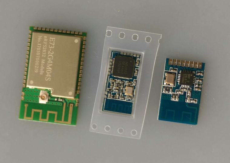
First nrf51822 module arrived already.
It's really small, here between an nrf24 SMD and the cdebyte 52832.
Soldering quality looks better than the pictures on AliExpress.
Note sure how this fits into the comparative size of things, but it looks interesting:
https://www.aliexpress.com/item/NRF52832-Module-Core-Board-Wireless-Bluetooth-Transceiver-Module-Transparent-Transmission-Code-NRF51822-Migration-Guide/32797905798.html?spm=a2g0s.13010208.99999999.280.9VhQow -
Anyone have a good sketch for measuring the battery supplied voltage on an nRF52? Some of the concepts from the old atmega328p may apply, but the specifics are going to be different, I'm sure.
-
Check on adafruits feather reference they use two resistors as a voltage divider for that simple and effective.
@Mike_Lemo said in nRF5 Bluetooth action!:
Check on adafruits feather reference they use two resistors as a voltage divider for that simple and effective.
I'm not finding it. Do you have a link?
-
@Mike_Lemo said in nRF5 Bluetooth action!:
Check on adafruits feather reference they use two resistors as a voltage divider for that simple and effective.
I'm not finding it. Do you have a link?
-
@Mike_Lemo said in nRF5 Bluetooth action!:
Check on adafruits feather reference they use two resistors as a voltage divider for that simple and effective.
I'm not finding it. Do you have a link?
-
-
Well, as you all know, on the atmega328p you can read the 1.1v gap voltage using the battery voltage as the reference voltage, by doing analogRead(A0), and from just that one measurement then calculate the battery voltage by doing a little bit of math. So, I'm just wondering what the code is to do the equivalent of that (using 1.2v instead of 1.1v) on the nRF52832.
-
If supplied with less than 3.6V you can do it with ADC, 1.2V voltage reference and 1/3 prescaling.
But I've only looked at the theory yet.Rules are Vdd+0.3V max at the pin, and max 2.4V as input of ADC (after prescaling)
@Nca78 said in nRF5 Bluetooth action!:
If supplied with less than 3.6V you can do it with ADC, 1.2V voltage reference and 1/3 prescaling.
But I've only looked at the theory yet.For this, you can use the implemented hwCPUVoltage() function. Reading the voltage costs nRF51: 260µA/20µs | nRF52: 700µA/3µs
-
@d00616 said in nRF5 Bluetooth action!:
hwCPUVoltage()
I'm finally installing Visual Micro, because I hope it will help me quickly find where all these functions are defined. With all these new layers, the Arduino IDE is just no longer cutting it.
-
@d00616 said in nRF5 Bluetooth action!:
hwCPUVoltage()
I'm finally installing Visual Micro, because I hope it will help me quickly find where all these functions are defined. With all these new layers, the Arduino IDE is just no longer cutting it.
LOL. Well, Visual Micro found it alright, but just in the wrong place. It found it in MyHwAVR.cpp
-
@d00616 said in nRF5 Bluetooth action!:
hwCPUVoltage()
I'm finally installing Visual Micro, because I hope it will help me quickly find where all these functions are defined. With all these new layers, the Arduino IDE is just no longer cutting it.
@NeverDie said in nRF5 Bluetooth action!:
@d00616 said in nRF5 Bluetooth action!:
hwCPUVoltage()
I'm finally installing Visual Micro, because I hope it will help me quickly find where all these functions are defined. With all these new layers, the Arduino IDE is just no longer cutting it.
good choice :+1:
for nrf5, the function is located in MyHwNRF5.cpp -
@Nca78 said in nRF5 Bluetooth action!:
If supplied with less than 3.6V you can do it with ADC, 1.2V voltage reference and 1/3 prescaling.
But I've only looked at the theory yet.For this, you can use the implemented hwCPUVoltage() function. Reading the voltage costs nRF51: 260µA/20µs | nRF52: 700µA/3µs
@d00616 said in nRF5 Bluetooth action!:
For this, you can use the implemented hwCPUVoltage() function.
I tried this function call on an nRF52 DK, and it seems to work. I then tried it on an Ebyte module, treated as an nRF52 DK "board", and it reported zero voltage. So, probably I just need to do a pin mapping so that it reads the voltage on the proper pin. But which pin/mapping would it be? I thought that Vcc wouldn't really be mappable to anything but Vcc. I guess whichever analog pin (if that's what it is?) is connected to Vcc on the nRF52 DK is the pin I need to find and re-map to its equivalent pin on the Ebyte module. Hmmm.... I'll have to look into which one that would be.
-
Actually, something different may be going on. Here's the function definition:
uint16_t hwCPUVoltage()
{
	// VDD is prescaled 1/3 and compared with the internal 1.2V reference
	Serial.println("Inside hwCPUVoltage function.");
#if defined(NRF_ADC)
    Serial.println("This is an NRF_ADC.");
	// NRF51:
	// Sampling is done with lowest resolution to minimize the time
	// 20uS@260uA

	// Concurrent ressource: disable
	uint32_t lpcomp_enabled = NRF_LPCOMP->ENABLE;
	NRF_LPCOMP->ENABLE = 0;

	// Enable and configure ADC
	NRF_ADC->ENABLE = 1;
	NRF_ADC->CONFIG = (ADC_CONFIG_EXTREFSEL_None << ADC_CONFIG_EXTREFSEL_Pos) |
	                  (ADC_CONFIG_PSEL_Disabled << ADC_CONFIG_PSEL_Pos) |
	                  (ADC_CONFIG_REFSEL_VBG << ADC_CONFIG_REFSEL_Pos) |
	                  (ADC_CONFIG_INPSEL_SupplyOneThirdPrescaling << ADC_CONFIG_INPSEL_Pos) |
	                  (ADC_CONFIG_RES_8bit << ADC_CONFIG_RES_Pos);
	NRF_ADC->EVENTS_END = 0;
	NRF_ADC->TASKS_START = 1;
	while(!NRF_ADC->EVENTS_END);
	NRF_ADC->EVENTS_END = 0;
	int32_t sample = (int32_t)NRF_ADC->RESULT;
	NRF_ADC->TASKS_STOP = 1;
	NRF_ADC->ENABLE = 0;

	// Restore LPCOMP state
	NRF_LPCOMP->ENABLE = lpcomp_enabled;

	return (sample*3600)/255;

#elif defined(NRF_SAADC)
	// NRF52:
	// Sampling time 3uS@700uA
	Serial.println("This is an NRF_SAADC.");
	int32_t sample;
	NRF_SAADC->ENABLE = SAADC_ENABLE_ENABLE_Enabled << SAADC_ENABLE_ENABLE_Pos;
	NRF_SAADC->RESOLUTION = SAADC_RESOLUTION_VAL_8bit << SAADC_RESOLUTION_VAL_Pos;
	NRF_SAADC->CH[0].PSELP = SAADC_CH_PSELP_PSELP_VDD << SAADC_CH_PSELP_PSELP_Pos;
	NRF_SAADC->CH[0].CONFIG = (SAADC_CH_CONFIG_BURST_Disabled << SAADC_CH_CONFIG_BURST_Pos) |
	                          (SAADC_CH_CONFIG_MODE_SE << SAADC_CH_CONFIG_MODE_Pos) |
	                          (SAADC_CH_CONFIG_TACQ_3us << SAADC_CH_CONFIG_TACQ_Pos) |
	                          (SAADC_CH_CONFIG_REFSEL_Internal << SAADC_CH_CONFIG_REFSEL_Pos) |
	                          (SAADC_CH_CONFIG_GAIN_Gain1_6 << SAADC_CH_CONFIG_GAIN_Pos) |
	                          (SAADC_CH_CONFIG_RESN_Bypass << SAADC_CH_CONFIG_RESN_Pos) |
	                          (SAADC_CH_CONFIG_RESP_Bypass << SAADC_CH_CONFIG_RESP_Pos);
	NRF_SAADC->OVERSAMPLE = SAADC_OVERSAMPLE_OVERSAMPLE_Bypass << SAADC_OVERSAMPLE_OVERSAMPLE_Pos;
	NRF_SAADC->SAMPLERATE = SAADC_SAMPLERATE_MODE_Task << SAADC_SAMPLERATE_MODE_Pos;
	NRF_SAADC->RESULT.MAXCNT = 1;
	NRF_SAADC->RESULT.PTR = (uint32_t)&sample;

	NRF_SAADC->EVENTS_STARTED = 0;
	NRF_SAADC->TASKS_START = 1;
	while (!NRF_SAADC->EVENTS_STARTED);
	NRF_SAADC->EVENTS_STARTED = 0;

	NRF_SAADC->EVENTS_END = 0;
	NRF_SAADC->TASKS_SAMPLE = 1;
	while (!NRF_SAADC->EVENTS_END);
	NRF_SAADC->EVENTS_END = 0;

	NRF_SAADC->EVENTS_STOPPED = 0;
	NRF_SAADC->TASKS_STOP = 1;
	while (!NRF_SAADC->EVENTS_STOPPED);
	NRF_SAADC->EVENTS_STOPPED = 1;

	NRF_SAADC->ENABLE = (SAADC_ENABLE_ENABLE_Disabled << SAADC_ENABLE_ENABLE_Pos);

	return (sample*3600)/255;
#else
	Serial.println("Unknown MCU!!");
	// unknown MCU
	return 0;
#endif
}
One, perhaps likely, theory would be that it doesn't recognize the MCU, which would explain why it returns the value of zero. Well, to debug that, I added the Serial.println(...) statements into the library code (see above) in an attempt to see which of the if-else branches is being taken, but none of the Serial.println(...)'s were printed! Here's a sample of the output from the Ebyte Module:
332641 TSF:MSG:SEND,255-255-255-255,s=255,c=3,t=7,pt=0,l=0,sg=0,ft=0,st=OK:
332968 TSF:MSG:READ,0-0-255,s=255,c=3,t=8,pt=1,l=1,sg=0:0
332973 TSF:MSG:FPAR OK,ID=0,D=1
334649 TSM:FPAR:OK
334650 TSM:ID
334651 TSM:ID:REQ
334654 TSF:MSG:SEND,255-255-0-0,s=59,c=3,t=3,pt=0,l=0,sg=0,ft=0,st=OK:
336662 TSM:ID
336663 TSM:ID:REQ
336665 TSF:MSG:SEND,255-255-0-0,s=23,c=3,t=3,pt=0,l=0,sg=0,ft=0,st=OK:
338673 TSM:ID
338674 TSM:ID:REQ
338676 TSF:MSG:SEND,255-255-0-0,s=242,c=3,t=3,pt=0,l=0,sg=0,ft=0,st=OK:
340684 TSM:ID
340685 TSM:ID:REQ
340687 TSF:MSG:SEND,255-255-0-0,s=205,c=3,t=3,pt=0,l=0,sg=0,ft=0,st=OK:
342695 !TSM:ID:FAIL
342696 TSM:FAIL:CNT=7
342698 TSM:FAIL:DIS
342700 TSF:TDI:TSL
402703 TSM:FAIL:RE-INIT
402705 TSM:INIT
402706 TSM:INIT:TSP OK
402708 TSM:FPAR
402711 TSF:MSG:SEND,255-255-255-255,s=255,c=3,t=7,pt=0,l=0,sg=0,ft=0,st=OK:
403472 TSF:MSG:READ,0-0-255,s=255,c=3,t=8,pt=1,l=1,sg=0:0
403478 TSF:MSG:FPAR OK,ID=0,D=1
404719 TSM:FPAR:OK
404720 TSM:ID
404721 TSM:ID:REQ
404724 TSF:MSG:SEND,255-255-0-0,s=241,c=3,t=3,pt=0,l=0,sg=0,ft=0,st=OK:
406732 TSM:ID
406733 TSM:ID:REQ
406735 TSF:MSG:SEND,255-255-0-0,s=205,c=3,t=3,pt=0,l=0,sg=0,ft=0,st=OK:
408743 TSM:ID
408744 TSM:ID:REQ
408747 TSF:MSG:SEND,255-255-0-0,s=168,c=3,t=3,pt=0,l=0,sg=0,ft=0,st=OK:
410754 TSM:ID
410755 TSM:ID:REQ
410757 TSF:MSG:SEND,255-255-0-0,s=131,c=3,t=3,pt=0,l=0,sg=0,ft=0,st=OK:
412765 !TSM:ID:FAIL
412766 TSM:FAIL:CNT=7
412768 TSM:FAIL:DIS
412770 TSF:TDI:TSL
472773 TSM:FAIL:RE-INIT
472775 TSM:INIT
472776 TSM:INIT:TSP OK
472778 TSM:FPAR
472781 TSF:MSG:SEND,255-255-255-255,s=255,c=3,t=7,pt=0,l=0,sg=0,ft=0,st=OK:
472955 TSF:MSG:READ,0-0-255,s=255,c=3,t=8,pt=1,l=1,sg=0:0
472960 TSF:MSG:FPAR OK,ID=0,D=1
474789 TSM:FPAR:OK
474790 TSM:ID
474791 TSM:ID:REQ
474794 TSF:MSG:SEND,255-255-0-0,s=167,c=3,t=3,pt=0,l=0,sg=0,ft=0,st=OK:
476802 TSM:ID
476803 TSM:ID:REQ
476805 TSF:MSG:SEND,255-255-0-0,s=131,c=3,t=3,pt=0,l=0,sg=0,ft=0,st=OK:
478813 TSM:ID
478814 TSM:ID:REQ
478816 TSF:MSG:SEND,255-255-0-0,s=94,c=3,t=3,pt=0,l=0,sg=0,ft=0,st=OK:
480824 TSM:ID
480825 TSM:ID:REQ
480827 TSF:MSG:SEND,255-255-0-0,s=57,c=3,t=3,pt=0,l=0,sg=0,ft=0,st=OK:
482835 !TSM:ID:FAIL
482836 TSM:FAIL:CNT=7
482838 TSM:FAIL:DIS
482840 TSF:TDI:TSL
I'm not quite sure how to interpret that, but pretty clearly it doesn't contain the println's that I was expecting.
Any theories as to what's going on?
-
Bracketing that and setting it aside, I do now notice this line in the BatteryPoweredSensor demo sketch:
int BATTERY_SENSE_PIN = A0; // select the input pin for the battery sense pointSo, if I map that A0 in the sketch to the A0 of the Ebyte Module, then maybe (hopefully) the voltage measurement will work on the Ebyte Module. I'll give it a try.
-
Unfortunately, after I add:
#include <mySensors.h>the locus of control goes somewhere else (I guess the gateway or something?). Anyhow, it makes this very hard to debug.
For instance, the pin of interest is PIN_AIN0. I can't find where it's defined, and I can't print out its value either, because of this locus of control issue.
Anyhow, I think I may wait for others to get up and running with their modules, and start facing the same issues. Maybe then we can help each other figure this stuff out.